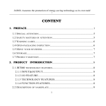
1
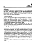
Series FiveTM
Programmable Controller
Operator Interface Unit
User's Manual
GE Fanuc Automation
October 1988
WARNING, CAUTION, AND NOTES AS USED IN THIS PUBLICATION
E l
WARNING
Warning notices are used in this publication to emphasize that hazardous voltages, currents, temperatures,
or other conditions that could cause personal injury exist in this equipment or may be associated with its
use.
In situations where inattention could cause either personal injury or damage to equipment, a Warning
notice is used.
E l
CAUTION
Caution notices are used where equipment might be damaged if c& is not taken.
NOTE
Notes merely call attention to infoxmation that is especially significant to understanding and operating the
equipment..
This document based on information available at the time of its publication. While efforts have been made to be accurate, the
information contained herein does not purport to cover all details or variations in hardware and software, nor to provide for
every possible contingency in connection with installation, operation, and maintenance. Features may be described herein
which are not present in all hardware and software systems. GE Fanuc Automation assumes no obligation of notice to
holders of this document with respect to changes subsequently made.
GE Fanuc Automation makes no representation or warranty, expressed, implied, or statutory with respect to, and assumes no
responsibility for the accuracy, completeness, sufficiency, or usefulness of the information contained herein. No warranties
of merchantability of fitness for purpose shall apply.
(01988 CE Fanuc Automation North America, Inc.
Preface
iii
The Operator Interface Unit (OIU) for the Series FiveTMProgrammable Logic Controller (PLC) is a
compact portable hand-held device that allows the factory floor engineer or operator to monitor 110 and
register references, diagnose system faults, display user defined messages, upload and download CPU
memory to and from memory cartridges, configure a GeniusTMI/O network, program EPROM memory
cartridges, and perform a number of other functions.
This manual contains the information required by the user to install and operate the Series Five Operator
Interface Unit.
Chapter 1, Introduction: provides an overview of the OW, with emphasis on its physical capabilities,
the function of each key, and its function within the Series Five PLC system.
Chapter 2, Monitor Mode: describes how to access the monitor mode of operation in order to monitor
110 references, monitor register references, use different display formats, set and search for overrides,
force 110 references on or off, and write to I/Oand register references.
Chapter 3, Menu Mode: describes the options available to the user when accessing any of the nine
main menus and their sub-menus to perfom any of the many operations available through these menus.
Chapter 4, TimerICounter Mode: describes how to access timer and counter "special" registers, in
order to monitor, write to, or set timer and counter preset and accumulator values.
Appendix A, Error Messages: provides a list of error messages that may be displayed on the OIU, the
cause of each error, and the action required to clear the enor.
Appendix B, Menu Map: provides a map of the operations and functions available through each of the
OIU modes of operation.
Appendix C, Accessories and Serial Port Information: provides catalog numbers of the OIU and
related accessories, and pin descriptions of the serial ports in the OIU.
Related Publications
GFK-0122 Series Fivem PLC User's Manual
GFK-0123 Series Fivem I/O Module Specifications
GFK-0023 Logicmasterm 5 Programming and Documentation Software User's Manual
GEK-25376 Series Threem PLC User's Manual
GEK-90846 GeniusTMI/OSystem Manual
GFK-0248 Series Fivem Genius Bus Controller User's Manual
Henry A. Konat
Senior Technical Writer
Content
CHAPTER 1.
INTRODUCTION
Purpose of the Operator Interface Unit
General Description
Operating Modes
Features of the OIU
Environmental Features
Using the OIU Keypad
Format Keys
Timer/Counter Keys
Table Keys
Data Entry Keys
Installing the OIU
OIU Power Consumption
Getting Started
Initial Communication
Communication Problems
CHAPTER 2.
MONITOR MODE OF OPERATION
M o n i t o ~ gI/O References
Monitoring Channelized I/O References
Moving the Cursor
Changing Display Formats While Monitoring UO
Reference Tables
Display Formats
Forcing 110 Points
Valid Ranges for Displays
Setting, and Resetting Ovemdes
Searching For Ovemdes
Forcing Values in Display Formats
Monitoring Data Registers
Display Formats for Monitoring Registers
Writing to Data Registers
CHAPTER 3.
MENU MODE OF OPERATION
Accessing Menu Mode
Selecting a Menu or Sub-Menu
Description of Main and Sub-Menus
Main Menu 1 - PC Mode Control
Main Menu 2 - Operator Messages
Communications Pointers
Example of Message Display
Purpose of Register 4070
Main Menu 3 - Register Commands
Sub-Menu 3 1 - Clear All Registers
Sub-Menu 32 - Clear Register Range
Sub-Menu 33 - Data Search
Main Menu 4 - I/O Configuration
Sub-Menu 41 - System Allocation
Base Unit Display
Content
Sub-Menu 42 - Module Diagnostics
Sub-Menu 43 - LED Mode
Module Address Display Format
Sub-Menu 44 - Power-Up Configuration Check
Sub-Menu 45 - Select Configuration
Sub-Menu 46 - Force Cod~guration
Sub-Menu 47 - Read from or Write to an Intelligent
Module
Main Menu 5 - CPU Configuration
Sub-Menu 51 - Show Program Name
Sub-Menu 52 - Set Date and Time
Sub-Menu 53 - Show Scan Times
Sub-Menu 54 - Set Software Watchdog Timer
Sub-Menu 55 - CPU ID
Sub-Menu 56 - Reset All Overrides
Main Menu 6 - OIU Configuration
Sub-Menu 61 - Show Revision Numbers
.Sub-Menu 62 - Buzzer 0dOff
Sub-Menu 63 - Back-Light On/Off
Sub-Menu 64 OIU OdOff-Line
.
Sub-Menu 65 - Self-Diagnostics
Main Menu 7 - Memory Cartridge
Prompts for Copy Operations VeSication of Copy Operations
Storing User Logic and Data Registers
Copy +rations With password-~ssi~ned
Example With Two CPUs Password Protected
Sub-Menu 71 - Copy Data from CPU MC to OIU MC
Sub-Menu 72 - Copy Data from OIU MC to CPU MC
Verify that Data in the CPU Equals Data in OIU
Memory Cartridge
Checks Whether or Not the OIU Memory Cartridge is
Blank
Sub-Menu 75 - Clear All Data in the OIU Memory
Cartridge
Sub-Menu 76 - Display the Type and Size of the
Memory Cartridge Currently Installed in the OIU and
the CPU
Copy Data from Cassette Tape to the QIU Memory
Cartridge
Loading a Program From Tape
Copy Data from the OIU Memory Camidge to
Cassette Tape
Storing a Program to Tape
Sub-Menu 79 - Verify Cassette Tape Data Equals OIU
Memory Cartridge Data
Memory Cartridge Equals Tape Operation
Sub-Menu 7A - Copy Data from an External Computer
to the OIU Memory Caruidge
-
Content
vii
GFK-0181
Sub-Menu 7B - Copy Data from the OIU Memory
Cartridge to an External Computer
Main Menu 8 - Password control
Sub-Menu 8 1 - Unlock CPU
Sub-Menu 8 2 - Lock CPU
Main Menu 9 - Genius Network Configuration
Sub-Menu 91 - Set Up Genius Bus Controller (GBC)
Starting Address
Broadcast Data Length
Directed Data Length
Serial Bus Address for Broadcast (Global) Data
Example of Setting Up a Genius Bus Controller
Sub-Menu 92 - Display Genius ID
CHAPTER 4.
APPENDM A.
APPENDM B.
APPENDM C.
TIMERICOUNTER MODE
Timer/Counter Preset and Accumulate Registers
Monitoring Timers and Counters
Writing to Timers and Counters
Operator Interface Unit Error Messages
Operator Interface Unit Menu Map
Accessories and Serial Port Information
Catalog Numbers for OIU and Accessories
OIU 15-Pin Serial Port, OIU to CPU
8-Pin Serial Port - For connection to cassette tape
recorder or Personal Computer.
Figures
viii
Figure
Operator Interface Unit
OIU Installed on a Series Five PLC
OIU Features
OIU Keypad
CPU Mode Selection Keyswitch
Local Input Data Display (Default)
Channelized Input Data Display (Default)
Cursor Movement in Binary Format
Moving the Display Window With Next and Prev Keys
Changing Format of Data Display (VO References)
Changing Format of Data Display (Register References)
Display for Binary Format (16 Bits)
Display for Decimal Format (32 Bits)
Display for Signed Decimal Format (32 Bits)
Display for Double Precision Format (32 Bits)
Display for Hexadecimal Format (32 Bits)
Display for Text Format (64 Bits)
Forcing an Output On
Setting and Resetting Overrides
Writing a Word to 110 (Signed Decimal Format)
Writing a Word to I/O (Double Precision Format)
Writing a Word to Register (Decimal Format)
Writing a Word to Register (Hexadecimal Format)
Example of User Defined Message Display
Reading 110 Module Starting Address on Leds
Monitoring Timer Registers
Monitoring Counter Registers
Moving to the Next and Previous Timer
Writing a New Value to a Counter Accumulate Register
Monitor Mode of Operation
Timer/Counter Mode of Operation
Menu Mode of Operation
Menus 1 through 4
Menus 5 through 9
Pin Configuration, 8-pin Serial Port
Tables
Table
Environmental Characteristics
Reference Tables
Valid Ranges for Format
OIU Main Menus
User Defined Message Storage
Key Codes Generated in Menu 2
Key Codes Generated in OIU Self-check
Example of Tirner/Counter Special Register Area
Operator Interface Unit Error Messages
Introduction
This chapter provides the user with an introduction to and an overview of the use of the Operator
Interface Unit (OIU) for the Series Fivem Programmable Logic Controller. It includes a discussion of
the physical characteristics and features of the OIU, including the function or functions of each key, the
modes of operation, and connection of the OIU to a Series Five CPU.
Purpose of the Operator Interface Unit
The OIU is designed to provide factory floor operators and engineers with a convenient "window" into
the Series Five Programmable Logic Controller system. It is a compact, portable device capable of
performing powerful operations on the control system, as well as monitor vital 110 or register references, diagnose system faults, and display pre-programmed messages under control of the user logic
program to provide a visual indication of system status, or other relevant operator interface messages.
An illustration of the OIU is shown below. The features of the OIU are discussed in the following
paragraphs.
a42262
ENSURE C W KEY IS IN dlU POSmON
ANDOlU ISON- U N E W N U 6 4 )
MAIN M N U S
'DP
n
TEXT
IfX
E C
4
Y
o
OVRD MENU
C
REGISTER COMMANDS
YO CONFIGURATION
CPV CONFIGURATON
OIU CONffiURATlON
7 M E W CARTRCGE
8 PASSWORDCONTROL
9 GENIUS NETWCCIK
3
4
5
6
EX:TO MONITORCHANNEL2 INPUT 107
Figure 1-1. Operator Interface Unit
T
~
~
~
n
Introduction
General Description
The OIU is a compact device measuring only 4.6 inches (1 17 mrn) x 5.6 inches (142 mm) x 1.2 inches
(30 mrn) and weighing 24.7 ounces (380 grams). Because of its small size, the OIU is very portable and
is easily moved from system-to-system as required. The OIU is a powerful unit that allows the user to
monitor both 110 and registers in any of six different formats, force (write to) VO and register values,
ovemde selected I/O points, perform CPU and 110 system configuration operations, select the CPU
operating mode, program PROM and EEPROM memory cartridges, test memory cartridges, and perform many other useful operations on the Series Five PLC system:
The OIU can be connected to any Series Five CPU by one of two methods. It can be plugged directly
into the top CCM port connector (15 pin) on the CPU and secured by tightening the two captive screw
fasteners located at the top and bottom center of the OIU front. The second method is to connect the
OIU to the CPU through one of two available cables for user convenience. The catalog numbers and
lengths of these cables are IC655CBL540, 5 feet (1.5 m), or IC655CBW41, 10 feet (3.0 m).
With the OIU connected to a Series Five CPU you can access 110, register, and system data stored in the
CPU. Or - if the CPU to which it is attached is one of several on a GeniusTMnetwork, it can access the
110, register, and system data stored in any of the other CPUs on the network without the need to move
the OIU from one CPU to another.
.
-m
0
IIYW
OEFanw
*r*r
w
hRn
uoul;opmm
-S
@
.-.
35
,y(y
10
t
mamannn
m.
w*
UUffiriUI
m v ?
.vp
I.
I.
nem
: :,e:
11118..
1
I
,
I
,
I
l
,
6
.
l
nam
:m :
l a,=:
Y.
W 1 I I Y L . .
.IS,,.
,
."I...
-m
r t . rmmm
6.
-m
I.
.y'P -.'Py'LP
rnm r-a*.
-- -
-mn
-amn
m h R n
)uron*R
rnyp m.?yF
r ~ m
s w a m r.
n m ran.
r.
a42602
m ~ P m m ' # ~ ' L P L
ram s1.1.
rm
n . ,.at.
r.
-m
:: :::: :: ::.....
:::: :,.: :..I..IIrn.
: :: :: :: :: ::.....
:: :: :: :: :: :: :: :: :: ::
..I..DIm
A
C'.
am
..#
6.0,.
s o ,m
I.
7.
LD
I.
*-1.
C,.
I.
I.
1.0,.
I. I.
I . 9.
IO
6.
I... 8 .
1 m 7-
am
,.#D..#.
.IIOLYOI*m
.IRICLICO*rUm
IDUUWPRlm*
Figure 1-2. OIU Installed on a Series Five PLC
I.
m.
I.
,.#...I.
Cl. r.0,.
I.
I * I. 1 m I .
9.
7 m I. I .
a.
I.
.
,
I
.
-
Introduction
Operating Modes
The OIU can be commanded to operate in one of three modes:
Monitor Mode: Allows the user to monitor 110 and registers, write to 110 and registers, override 110
references, and force 110 references.
Menu Mode: Allows the user to perform a wide variety of useful system operations.
TimerICounter Mode: Allows the user to monitor timers and counters, and force timer and counter
preset and accumulator register values.
Features of the OIU
The physical features of the OIU are described below.
Liquid Crystal Display (LCD): The display for the OIU is a Liquid Crystal Display with two lines,
each 24 characters long. It provides a visual means for the user to monitor register and YO values,
force register and 1
1
0 values, display and select system parameters, and display diagnostic or error
messages. The user can program certain informative messages into ladder logic which can be
displayed on the LCD.
Contrast Adjustment Screw: Located on the left side of the OIU, this screw allows the LCD viewing
angle to be adjusted so that the characters on the screen can clearly be observed. This is especially
useful when the unit is permanently mounted.
CPU Mode LEDs: These are three indicators located at the upper left of the LCD display which show
the current operating mode of the CPU, either RUN (green LED), RUN with outputs disabled (amber
LED), or STOP (red LED).
Keypad: This is a keypad having 6 columns and 5 rows of keys, with which the OIU functions are
selected.
Port Connector: This provides the physical means for the OIU to be connected to the CPU, either
plugged directly into the CCM port's top connector on the Series Five CPU, or linked through a cable
5 feet (1.5m), IC655CBL540, or 10 feet (3.0m), IC655CBL541, in length.
Main Menu List: A convenient list of the OIU's main menu and an example showing how to monitor
specific references with the OIU is printed on the front of the OIU immediately to the left of the 6 x 5
keypad.
Memory Cartridge Slot: A slot, accessed through a hinged plastic cover, which allows a Series Five
PLC memory cartridge to be inserted in order to perform certain functions on it. These functions are:
copy to/from the CPU memory cartridge, verify that the content of the memory cartridge in the OIU is
the same as the content of the CPU memory cartridge, blank check or clear the memory cartridge,
display the memory cartridge type in the CPU and the OIU, and upload/download a program from a
cassette tape recorder or a personal computer. To perform these functions, the appropriate memory
cartridge must be inserted into this slot.
EPROM Memory Burner: A built-in EPROM burner for copying programs written on a memory
cartridge residing in the CPU, onto an EPROM cartridge inserted in the slot on the left side of the
OIU.
Captive Screw Fasteners: Two captive screws, one each at the top and bottom center front of the
OIU case, are used to attach the OIU securely.to the CPU when the OIU is plugged into the top CPU
port connector.
RS-232 Conznzrrnicatiorzs Port: An RS-232 port, accessed through a miniature 8-pin DIN connector
on the lower side panel of the OIU, which can connect to a cassette tape recorder or an external
Introduction
personal computer, or with a test connector installed, can perform certain diagnoaic checks on the
OIU.
The features described above are shown on the following illustration of an OIU.
CE Fanuc
SERIESFIVE
M
1
OIU
i
.cN
o m
OunDIs
12+0201 12+0193
12+0197. 100110001 1000011
I I I I I I I I ItSUU1211109 1 7 6 5 4 3 2 1
b
m D P 4
tO& C +/-
WX
~
LUII-
,
1 PCmQ*Ima
2 OPERATOR W O E S
3 REUSTER W D G
4 m OCNFDJRATlal
6 WCOWYURATMN
6 W COIFLURATIP(
7 -UTRIOOE
,
E
WRD LWU
@
J
~
C
I
Q
@
Q
SIDE VIEW
FRONT VIEW
q
10
lNl
BACK VlEW
b
'
\
BOlTOM VlEW
1.
2.
3.
4.
5.
Liquid Crystal Display
Contrast Adjustment Screw
CPU Mode LEDs
Keypad
Port Connector
6.
7.
8.
9.
10.
Main Menu List
Memory Cartridge Slot
EPROM Memory Burner
Captive Screw Fasteners
RS-232 Communications Port
Figure 1-3. OIU Features
Introduction
Environmental Features
Environmental characteristics of the OIU are listed in the following table.
Table 1-1. Environmental Characteristics
Operating Temperature:
Storage Temperature:
Humidity:
Atmosphere:
Vibration:
Shock:
Insulation:
0" to 60°C (32" to 140°F)
-10 to 65°C (14"to 168°F)
20% to 90%, non-condensing
No corrosive gases
Meets or exceeds MIL-STD 810C, method 514.2
Meets or exceeds MIL-STD 810C. method 516.2
1500 V ac for One minute
Using the OIU Keypad
The 6 x 5 keypad (6 columns x 5 rows) on the front of the OIU is used for selection of the OIU
functions. These functions are activated by pressing the appropriate key or combination of keys.
Shifted key functions are activated by pressing the SHFT (Shift) key followed by the appropriate key on
the key pad. Whenever the SHFT keySHFT key is active, a A appears at the top right of the OIU
display. The shifted function keys have yellow graphics above them to describe their function, while the
descriptive graphics for unshifted functions are white. All of the keys are gray, except for the SHFT
key, which is yellow.
TEXT
DP
II)
+/- OVRD MENU
mmmmpJm
Hm f DEC
D
E
F
7
8
9
~~~~~~
-BIN
DEC
ESC
TMR
CNT
4
5
6
PREV
mmmmF""1m
ON
OFF SRCH
3
NEXT
~~~~~~
REG
CHf
1
2
IN
OUT
CLR
0
j
.'.I..
.......
ENT SHFT
,..,......
Figure 1-4. OIU Keypad
Introduction
The SHFT function will remain active under certain conditions without the user being required to
reactive it more than once. An example of this is when entering a hexadecimal number, such as ABB3,
the SHFT key need only be activated twice - once before entering the first digit A, and again (required to
deactive (release) the SHFT key) before entering the final digit 3. In most cases, the SHFT key will
remain active for only one key operation after it has been activated. This helps to reduce the number of
keystrokes required to implement any given command on the OIU.
Format Keys
The four keys (four unshifted plus two shifted) in the top left comer of the keypad are the format keys.
When monitoring 110 references or registers, or when forcing values, these keys are used to select the
format in which the references will be displayed, or when data is entered by the user when forcing
values.
The keys, a description of the formats, and an example of each format are shown below (the same value
is shown for each example, but as the proper value for that format).
BIN
- Display will appear in binary notation - example: lOOOlOOOlOOOIOO0
HEX
- Display will appear in hexadecimal notation - erample: 8888
DEC
- Display will appear in unsigned decimal notation - example: 34952
f DEC - Display will appear in signed decimal notation - exomple: -30584
TEXT - Shified Function. Display will appear in ASCII notation - example: H H
- Shifted Function. Display will appear in signed double precision notation - example: +0000034592
DP
TimerICounter Keys
The two keys directly below the format keys (TMRand CNT) are used to access the
TIMER/COUNTER mode of operation. Selection of one of these keys, followed by a timer or counter
number used in the Series Five logic program, tells the OIU to monitor the Preset and Accumulator
values of that timer or counter. It also gives the user the ability to force a new value into either of the
registers containing the monitored values.
Table Keys
The group of four keys (REG, CH+, IN, 0UT)in the lower left comer of the keypad are for selection of
the table required for an operation. These keys specify whether the address selected is a register, a local
input point, a local output point, or a channelized input or output point. The Series Five reference tables
are listed in the following table.
Table 1-2. Reference Tables
I
TABLE
Local Input
Local Output
Channel 1 + Input
Channel 1+ Output
Channel 2+ Input
Channel 2+ Output
Channel 1- Special Purpose Inputs
Channel 1- Internal Corls
Channel 2- Internal Coils
Data Registers
I
ADDRESS RANGE
I
I1 to I1024
01 to 01024
I1+1 to 11+1024
01+1 to 01+1024
I2+1 to 12+1024
02+1 to 02+1024
11-1 to 11-512 (Read Only)
01-1 to 01-1024
02-1 to 02- 1024
R1 to Rmax *
* Rrnax will be either 4096 or 16384, as determined by the size of the Register Memory RAM installed in the CPU.
Introduction
For more detailed information about each of the reference tables, refer to the Series Five PLC User's
manual, GFK-0122.
Data Entry Keys
The group of keys to the right center of the keypad are for selection of numerical values to be entered on
the OIU. These keys are labeled 0 through 9, and shifted functions A through F.
The remaining keys all have individual meanings, and are discussed separately.
-->
c--Key
+/- Key
OVRD Key
MENU Key
ESC Key
PREV and NEXT'Keys
SRCH Key
CLR Key
ENT Key
This key has two functions. The left arrow (c--)
can be used to erase the last character
entered on a display in which the user is required to make an entry. Both the left (<-) and
right (-->) arrows can be used to move the cursor on the LCD display when in certain
menus and monitor formats. These arrow movements are described in detail in the
applicable sections later in this manual.
This key is used in conjunction with the numerical keys when forcing values in either the
double precision or signed decimal formats. The + and signs are toggled on alternate
depressions of the key and must be pressed immediately before the value to be entered.
This key is used when in the Monitor Mode to set or reset overrides on individual UO
points. Overridden references can then be forced on or off using the ON or OFF keys,
which are shifted functions, located on the keypad above the numbers 2 (ON) and 3 (OFF)
keys.
This key is used, in conjunction with the numerical keys, to access the MENU Mode of
.
operation. Refer to Chapter 3 for a detailed discussion of this mode.
This key is used when in the MENU mode to either cancel the cumnt operation or to exit
from the MENU mode. It is also used in the TIMERJCOUNTER and MONITOR modes to
cancel a forced write to a register or 110 table.
These keys are used in both the MONITOR and MENU modes. In the MENU mode, they
are used to page forward or backward through the menu options, and in MONITOR mode
to page through groups of references, which can be either 40 tables or registers.
This key is used to search for overridden references; for example, when you want to leave
the system to operate normally after performing some tests using the ovenide function. The
key is valid only when in the MONITOR mode and each 110 table needs to be checked. If
an override is found, the cursor will appear under this reference and the user can then reset
the override with the OVRD key. When there are no more overrides set in the current table,
the message NO OVERRIDES FOUND will be displayed.
This key is used to clear the content of the current entry on the LCD display, whether it is a
monitor screen, an incomplete forced value, or an exit from MENU mode after certain
menus have been used.
This key is used to complete entry of any required reference or value, or as the confirmation
that you wish to access a particular menu or operation within a menu.
-
Installing the OIU
Installation of the OIU is easy, simply connect the OIU to the tbp CCM port connector on the Series
Five CPU. When the OIU is connected through a cable, and is in the on-line mode, communications
will be lost with any device that is attached to the lower port connector. The user must be aware of this
when using the OIU with a system that is in the CPU RUN mode and if there is a serial device (such as a
Workmaster computer) attached to the lower port connector. However, after connection to the CPU, the
OIU, if in the ON-LINE mode, can be forced OFF-LINE by accessing MENU 64, which allows the
device connected to the lower port connector to regain communications.
NOTE
The OIU, when connected, .will power-up in the mode that it was in the last time that it was
connected to the CPU. For example, if it had been commanded to be OFF-LINE, it will
power-up OFF-LINE.
OIU Power Consumption
When the OIU is connected to the CPU, the OIU draws its power from the Series Five power supply.
The OIU typically consumes approximately 400 mA of current, however, it can use up to 1 A when
burning EPROMs. This maximum current consumption figure must be included in the system loading
calculations when selecting a power supply for the CPU base unit.
Getting Started
When the OIU is initially connected, the amber colored backlight on the LCD display will turn on, and
one of the three LEDs at the left of the LCD will also turn on to indicate the current mode of the CPU,
which will be either RUN, OUT DIS (RUN with Outputs Disabled), or STOP.' The user must be aware
that the OIU will only be able to perform two-way communications with the CPU if the three-position
mode selection keyswitch on the CPU is in the OIU (center or vertical) position.
Figure 1-5. CPU Mode Selection Keyswitch
Switch shown in correct position for communication with the OIU.
Initial Communication
When the OIU is first connected, the LCD display will normally be blank. Certain menu displays may be
retained at power-down and displayed on power-up, such as "USER PROGRAM MESSAGES". Also, if
there is an error in the system, or a communications problem exists between the OIU and the CPU, an
error message will be displayed. This error message gives the user an indication of the cause of the
fault. For example, if the error is:
E252 NEW 1/0 CONFIG
.
Introduction
the user must access MENU 45 (see details in Chapter 3) before trying to put the CPU into the RUN
mode. If no error messages are displayed, then all self checking of the OIU has been completed
successfully. The user can then access one of the three OIU modes (MONITOR, MENU, or
TIMERICOUNTER) to exchange and display information on the LCD.
A complete list of error messages, their probable cause, and what to do to fix the problem causing the
error can be found in Appendix A of this manual.
Communication Problems
If for some reason, there does not seem to be any communication between the OIU and the CPU, check
the following.
1. If connected through an OIU to CPU cable, ensure that the cable is firmly connected to both the
OIU and the CPU, and is securely tightened with the cable's captive screw fasteners.
2. If the OIU is connected directly to the CPU without a cable, ensure that the two captive screws on
the OIU have been securely tightened.
3. Ensure that the OIU is ON-LINE (MENU 64).
4. Ensure that the CPU mode selection keyswitch is in the OIU position.
If after these checks have been made, you still do not have cornmunications between the OIU and the
CPU, please call your local GE Fanuc PLC distributor for technical support.
Monitor Mode of Operation
This chapter provides the information required to access and use the MONITOR MODE of operation
with the Series Five OIU. It describes the available options for monitoring or forcing references or
values. The different types of data formats are described, along with the ovemde capabilities of the
OIU, the search for overrides feature, and the forcing of discrete references on and off.
Monitoring LIO References
The OIU can monitor 110 tables and data registers in any one of six different formats; binary,
hexadecimal, decimal, signed decimal, double precision, and text. The default format for monitoring
110 points is binary, which is automatically displayed on the LCD display when the reference for an 110
point is entered with the keypad, similar to the example printed on the front of the OIU. In this format,
16 consecutive references are monitored simultaneously.
A specific 110 point is monitored by entering the reference for that point. The starting number on the
display defaults to the fist reference of the byte in which the requested reference occurs. Before doing
all of this, ensure that you are not in the MENU mode. If you are - exit that mode by using either the
ESC or CLR key (determined by where you are in the menu), then you are ready to enter the
MONITOR mode.
The following example shows how to monitor a .reference in the Local 110 chain. First, clear the LCD
display - then, enter the reference, by first pressing either the IN or the OUT key, followed by the point
reference number, and finally the ENT key.
DISPLAY
KEY
B I N
I 0 0 9 9
1 0 1 0 5
1 0 0 9 7
1 0 1 1 0 1 0 0 1 0 1 0 0 0 1 1
Figure 2-1. Local Input Data Display (Default)
-
Monitor Mode of Operation
2-2
Monitoring Channelized 110 References
To monitor any of the channelized 1/0references, i.e., Channel l+,Channel 2+, Channel I-, or Channel
2-, the channel number and + or -, as applicable, must be specified. First enter IN or OUT, then the
channel number. Next, pressing the CH key once selects a +, which is displayed after the channel
number. Alternate pressing of this key toggles between the + and -. After the desired channel and
reference table have been selected, select the reference number, followed by the ENT key.
DISPLAY
KEY
B I N
I 1 - 0 0 0 4
I 1 - 0 0 0 9
I 1 - 0 0 0 1
0 0 1 1 0 0 1 0 1 1 1 O J O 0 1
Figure 2-2. Channelized Input Data Display (Default)
The <-- key can be used anytime before the ENT key is pressed to delete the last character entered, or
the CLR key can be pressed to clear the complete entry if you wish to restart the sequence. If an invalid
Monitor Mode of Operation
address is entered, it will be detected by the OIU after the ENT key is pressed. You can change your
entry anytime before this without an error being detected.
After these keystrokes have been completed, the LCD will display:
1. The default format (BIN) in the leftmost position on the top row of the display.
2. The reference keyed in is displayed in the leftmost position of the bottom row
3. Two reference values on the top row, which are the addresses of the references on the byte
boundaries (first reference of each byte) immediately below and above the keyed-in reference
4. The status of the 16 references, beginning with the first reference of the least significant byte (lower
byte). The reference that you keyed-in is distinguished by an underscore cursor directly below the
reference bit position.
Moving the Cursor
The cursor can be moved among the 16 displayed points by using the left and right arrow keys. The
reference value in the lower left of the display will change to reflect the cursor position as the cursor
moves. The cursor will wraparound at either end of the display as illustrated in the following example.
KEY
DISPLAY
B I N
0 0 1 1 1
0 0 1 0 5
0 0 0 9 7
0 ~ 1 0 0 0 1 1 1 0 1 0 1 1 0 1
B I N
0 0 1 1 2
0 0 1 0 5
0 0 0 9 7
~ -0 0 1 0 0 0 1 1 1 0 1 0 1 1 0 1
B I N
0 0 0 9 7
0 0 i o 5
0 0 0 9 7
0 0 1 0 0 0 1 1 1 0 1 0 1 1 0 1
B I N
0 0 0 9 7
. 0 0 1 0 5
0 0 0 9 7
A
0 0 1 0 0 0 1 1 1 0 1 0 1 1 0 1
B I N
0 0 1 1 2
-0
-
-
0 0 1.0 5
0 0 0 9 7
A
0 1 0 0 0 1 1 1 0 1 0 1 1 0 1
Figure 2-3. Cursor Movement in Binary Format
Monitor Mode of Operation
2-4
The NEXT and P W V keys can be used to move 16 references at a time. The NEXT key increments
both the byte boundary references and the cursor reference by 16 bits, while the PREV key decrements
these references by 16 bits. 1/0references in binary format are incremented and decremented by 8 bits.
DISPLAY
KEY
T E X T
T E X T .
R 1 0 2 5 3
R 1 0 2 5 5
4
R
? " 0
6
7
D
R l O 2 5 2
a
B I N
0
1 9 8
B I N
0
1 9 0
b
4
R
R 1 0 2 5 4
? " 0
6
e
7
0 0 2 0 1
0 0 1 9 3
0 0 1 0 0 0 1 1 1 0 ~ 0 1 1 0 1
0 0 1 9 3
0 0 1 8 5
1 0 1 0 1 1 0 1 0 0 ~ 1 1 0 0 1
Figure 2-4. Moving the Display Window With Next and Prev Keys
To change from monitoring one 1/0 table to a different table, or to make a large jump in references
monitored, simply key-in the new reference. As soon as either the IN or OUT key is pressed, the bottom
line of the display will clear to accept the new references. When the ENT key is pressed, the display
will change to the specified table and reference address.
Changing Display Formats While Monitoring I/O Reference Tables
While in MONITOR mode, the display format can easily be changed by pressing the key corresponding
to the desired format. For example, to change from the default binary format to double precision (which
requires the shifted function key, DP), press the SHFT key, then the DP key. To revert back to binary
format, press the BIN key.
Several differences will occur in the display when changing formats. We have seen that in binary
format 16 bits of I/O information are displayed. However, when in decimal, signed decimal, double
prerision, and hexadecimal formats the equivalent of 32 bits of information is displayed, and in text
for, . ' the equivalent of 64 bits of information is displayed.
Monitor Mode of Operation
DISPLAY
KEY
B I N
0 0 1 9 8
0 0 2 0 1
0 0 1 9 3
0 0 1 0 0 0 1 1 1 0 ~ 0 1 1 0 1
T E X T
0 0
B I N
0 0 1 9 8
1 9 3
#
5
Z
0 0 2 2 5
A
Y
% " P
0 0 2 0 1
0 0 1 9 3
0 0 1 0 0 0 1 1 1 0 ~ 0 1 1 0 1
Figure 2-5. Changing Format of Data Display (I/0References)
KEY
DISPLAY
D E C
R 1 0 2 5 4
3 6 6 7 1
R 1 0 2 5 3
2 1 0 4 4
T E X T
R 1 0 2 5 3
4
R
? " O
R 1 0 2 5 5
6
7
D
R 1 0 2 5 4
8 F 3 F
R 1 0 2 5 3
2 5 3 4
H E X
Figure 2-6. Changing Format of Data Display (Register References)
e
Monitor Mode of Operation
Display Formats
The cursor seen beneath the particular 110 bit being monitored will disappear when a display format
other than binary is selected. The cursor will reappear in the same position relative to the display, even
though the display range may have been changed while in another format. This cursor position is to aid
the user when monitoring a particular bit; for example, by paging through the 110 tables to monitor the
third bit in each group of 16 bits.
The address of the 110 bit that the cursor is positioned beneath will also disappear when any format
other than binary is selected.
When in decimal, signed decimal, double precision, or hexadecimal formats, the starting addresses seen
on the upper left of the LCD will reflect that 32 bits are being monitored by being separated by 16 bits,
rather than 8 bits when in binary mode. Both of the displayed addresses always start on a byte
boundary, the same as in binary mode. Examples of each of the format displays for both 1/0 and
registers are shown in the following group of illustrations.
DISPLAY
.
Register :
B I N
R l O 2 5 3
0 1 0 1 0 0 1 0 0 0 1 1 0 1 0 0
B I N
I
1 9 8
I
2 0 1
I
1 9 3
0 0 1 0 0 0 1 1 1 0 1 0 1 1 0 1
-
-
Figure 2-7. Display for Binary Format (16 Bits)
DISPLAY
Register :
D E C
R 1 0 2 5 4
3 6 6 7 1
R l O 2 5 3
2 1 0 4 4
D E C
I
I
2 0 9
2 3 0 9 3
1 9 3
0 9 1 3 3
Figure 2-8. Display for Decimal Format (32 Bits)
DISPLAY
Register :
Figure 2-9. Display for Signed Decimal Format (32 Bits)
Monitor Mode of Operation
2-7
DISPLAY
R 1 0 2 5 4
R 1 0 2 5 3
- 1 8 9 1 6 7 5 5 9 6
D P
Register :
Figure 2-10. Display for Double Precision Format (32 Bits)
DISPLAY
Register :
H E X
R 1 0 2 5 4
8 F 3 F
R 1 0 2 5 3
2 5 3 4
H E X
I
I
2 0 9
5 A 3 5
1 9 3
2 3 A D
Figure 2-11. Display for Hexadecimal Format (32 Bits)
DISPLAY
Register :
T E X T
T E X T
R 1 0 2 ' 5 3
?
4
R
I
1 9 3
#
5
R l O 2 5 5
6
7
D
0
I
Z
A
e
2 2 5
Y
% " P
Figure 2-12. Display for Text Format (64 Bits)
Forcing 110 Points
It is possible to force 110 bits on or off in all display formats, except text. However, since Channel 11- is
read only, it can only be monitored with the OIU. There are two operations in which you can write to
110 references - bit write and word write. Bit write operations write to an individual bit when in binary
display format, while word write operations write to a group of 16 consecutive bits, or to 32 consecutive
bits when in double precision display format.
110 points can be overridden and then forced on or off individually, however, there is no limit to the
number of individual points that can be overridden in the system.
Valid Ranges for Displays
Valid ranges for each of the formats are listed in the following table.
.
Monitor Mode of Operation
Table 2-1. Valid Ranges for Format
I
FORMAT
Decimal
Signed Decimal
Double Precision
Hexadecimal
Binarv
Text
I
I
RANGE
0 to 65,536
-32,768 to +32,767
-2,147,483,648 to +2,147,483,647
0000 to FFFF
0000000000000000 to 1111111111111111
All ASCII characters programmed into OIU
firmware.
.
The LCD display must be in binary format to force an I/O point on or off. To force an UO point on or
off, move the cursor to the desired 40 point with the PREV,NEXT, -->, ancl <-- keys. Then, by
pressing the SHFT and ON keys the point is forced to a logical 1, or by pressing the SHFT and OFF
keys, the point is forced to a logical 0. However, since these points have not been overridden, any input
reference will only remain in its forced state for one scan, and any output reference will only remain in
its forced state while it is not written to by the user logic program. An example is shown below.
a42582'
DISPLAY
KEY
B I N
0 0 0 9 9
0 0 1 0 5
0 0 0 9 7
1 0 1 1 0 1 0 0 1 0 1 0 0 0 1 1
B I N
0 0 0 9 9
0 0 1 0 5
1 0 1 1 0
B I N
0 0 0 9 9
0 0 1 0 5
0 0 0 9 7
1 0 1 1 0 1 0 0 1 0 1 0 0 1 1 1
-
1
0
0
0 0 0 9 7
1 0 1 0 0
Figure 2-13. Forcing an Output On
-
A
~
1
1
Monitor Mode of Operation
2-9
Setting, and Resetting Overrides
In order to maintain an individual 110 point in the forced state, the reference must first be overridden by
pressing the OVRD key while the cursor is beneath the reference. You can then force the ovemdden
reference to a logical 1, using the SHFT ON key sequence, or to a logical 0, using the SHFT OFF key
sequence. To release a reference from the ovemdden state, reposition the cursor under the reference,
which will be flashing, and press the OVRD key.
a42583
DISPLAY
KEY
[OVRDl
[OVRDl
B I N
1 5
0 0 0 0 9
0 0 0 0.1
0 0 1 1 1 1 0 0 1 0 1 1 0 0 0 1
B I N
1 5
0 0 0 0 9
0 0 . 0 0 1
0 0 1 1 1 1 0 0 ~ 1 0 1 1 0 0 0 1
B I N
1 6
0 0 0 0 9
0 0 0 0 1
0 0 1 1 1 1 0 0 1 0 1 1 0 0 0 1
B I N
1 6
0 0 0 0 9
0 0 0 0 1
0 0 1 1 1 1 0 0 1 0 1 1 0 0 0 1
B I N
1 7
0 0 0 0 9
0 0 0 0 1
0 0 1 1 1 1 0 0 1 0 1 1 0 0 0 1
-
-
-
-
-
Figure 2-14. Setting and Resetting Overrides
Searching For Overrides
a i l e in the MONITOR mode, you can search for overridden references in the current YO table with
the SHFT SRCH key sequence. This function looks for the next ovemdden reference and positions the
cursor underneath of it, thereby allowing you to check for overrides before putting the system in RUN
mode or perhaps, while debugging your system.
Monitor Mode of Operation
If no ovemdden references are found after entering the S H l 3 SRCH key sequence, the message
NO OVERRIDES FOUND
will be displayed on the LCD display. All of the ovenides currently set in a system can be reset with a
single command while in sub-menu 56. A description of how to use that function can be found in
Chapter 3.
Forcing Values in Display Formats
As mentioned previously, values can be forced (written to) in all display formats, except text format.
While monitoring any of the numerical format displays, you can enter a new value as required. When
the first numeric key is pressed, the lower line of the LCD display will be blanked (except for the value
just entered) and you can proceed to enter the rest of the required value. When forcing these values,
remember that output references may be overwritten by the user program and input references 'will be
overwritten on the next scan UNLESS they have been previously ovemdden on a point-by-point basis
using the OVRD key.
When forcing a value in binary mode, enter the number as a string of 0's and l's, then press the ENT
key. Leading zeros can be ignored or included. In the ,decimal, signed decimal, and hexadecimal
formats which display the equivalent of 32 bits of information, only the least significant 16 bits can be
written to. The OIU will not let you enter more than 5 digits. When forcing .a value in double precision
format, you can write to all 32 bits.
DISPLAY
KEY
B I N
t 1 + O O 9 9
I 1 + 0 1 0 5
I 1 + 0 0 9 7
1 0 1 1 0 1 0 0 1 0 1 0 0 1 1 1
Figure 2-15. Writing a Word to 110 (Signed Decimal Format)
-
Monitor Mode of Operation
2-11
DISPLAY
KEY
[DPI
Figure 2-16. Writing a Word to 110 (Double Precision Format)
Monitoring Data Registers
As with the I/O references, data registers can be monitored in a l l six display formats. The number of
data registers available depends .on which RAM register memory device is installed in the CPU. This
can be either 4096 registers, which is standard, or 16384 registers (16K RAM supplied with 16K
memory cartridges).
NOTE
The register range, R3848 through R4096 is reserved for use by the Series Five CPU. It is
recommended that you do not use the monitor mode to write data to these registers.
To monitor a particular register, press the REG key, type the register number, then press ENT. The
LCD display will show two registers, with the register you entered on the right side of the LCD, and the
register with the next higher address on the left side. The value contained in the registers is displayed on
the bottom line, and the register reference numbers are displayed on the top line, above the value.
Display Formats for Monitoring Registers
The default format for monitoring registers is unsigned decimal. This is indicated by DEC, which is
displayed in the top left comer of the LCD display. The procedure for changing the display format is the
same as with 110 monitoring - just press the desired format key. In signed decimal and hexadecimal
Monitor Mode of Operation
2-13
a42587
KEY
[S HFT]
DISPLAY
H E X
R O O 0 4 1
0 0 0 0
R O O 0 4 0
B 7 9 2
H E X
9
R O O 0 4 1
R O O 0 4 0
H E X
9.
R O O 0 4 1
R O O 0 4 0
A
H E X
9 F.
R O O 0 4 1
R O O 0 4 0
A
H E X
R O O 0 4 1
0 0 0 0
R O O 0 4 0
0 0 9 F
Figure 2-18. Writing a Word to Register (Hexadecimal Format)
Chapter
3
Menu Mode of Operation
This chapter describes the options available to the user when using the OIU in the Menu mode of
operation. The functions available for each of the nine main menus and each of their sub-menus are
described. Most of these functions are available only with the OIU, however, some are also available
with Logicmaster 5 programming software. Those that are also available with Logicmaster 5 have a
statement to that effect in their description.
Accessing Menu Mode
As stated previously, the keyswitch on the CPU must be in the OIU position to have two-way
communications between the OIU and a Series Five CPU. The Menu mode is selected by pressing the
h/LENtTkey located in the top right comer of the keypad. There are nine main menus, each having two
or more sub-menus associated with them. Before entering the MENU mode, you should ensure that the
LCD display is blank, otherwise various enor messages may be generated and displayed on the LCD. A
summary of the function of the nine main menus is provided in the following table.
Table 3-1. OIU Main Menus
MENU
NUMBER
1
2
MENU NAME
PC MODE CONTROL
OPERATOR MESSAGES
REGISTER COMMANDS
110 CONFIGURATION
CPU CONFIGURATION
OIU CONFIGURATION
MEMORY CARTRIDGE
OPERATIONS
PASSWORD CONTROL
GENIUS NETWORK
CONFIGURATION
FUNCTION OF MENU ITEMS
Selects the CPU operating mode.
Displays messages generated by ladder logic program in ;he
CPU, and allows the operator to input instructions to the
program about those messages.
Clear register ranges and search for data in specific registers.
Local
Perform 110 diagnostics, select 110 configuration, *lay
YO Chain module types, and base unit and slot addresses.
Display and change some CPU parameters.
Display revision levels for finnware in OIU and CPU, display
and change certain OIU parameters, initiate self tests.
Copy either system parameters, register contents, or user ladder
logic from one memory cartridge to another, program EPROM
memory, erase contents of RAM and EEPROM memory
cartridges, verify content of memory cartridge in OIU against the
memory cartridge in the CPU, upload or download a program
from a cassette tape recorder or personal computer.
Used to logon and logoff a CPU to gain access to user logic
program.
Used in a system that links CPUs through a Genius network to
configure certain parameters for each bus controller in the
network.
Menu Mode of Operation
3-2
Selecting a Menu or Sub-Menu
One of the following procedures can be used to select a specific menu or sub-menu.
1. After ensuring that the LCD display is blank, enter the menu and sub-menu numbers on the keypad,
followed by the ENT key. The selected sub-menu will then be activated and displayed on the LCD.
For example, to activate sub-menu 3 (SHOW SCAN TIMES) in main menu 5 (CPU CONFIGURATION), press the following keys:
5 3 MENU E N T
2. The order of the above procedure can be altered, to produce the same results, as shown below.
MENU 5 3 E N T
3. Press the MENU key, then use the PREV and NEXT keys to page through the main menus. When
the desired main menu is displayed, select it with the ENT key, Then again using the PREV and
NEXT keys, page through the sub-menus of the selected main menu, and select the desired
sub-menu with the ENT key. For example, to select sub-menu 2 of main menu 3, the key sequence
would be:
MENU N E X T N'EXT E N T NEXT E N
Description of Main and Sub-Menus
Each of the main menus and sub-menus are described on the following pages. Throughout these
descriptions, the figure shown below is used to show in which CPU mode or modes a sub-menu may be
activated without causing an error message to be generated and displayed on the OIU's LCD display.
The mode or modes that can be used are indicated by an "X" in the appropriate box.
Run
Run WIOutputs Disabled
Stop
X
In the example of the figure, as shown above, the menu can be used only when the CPU is in the STOP
mode. An attempt to use that particular menu when the CPU is in any other mode, will result in an error
message being generated and displayed on the LCD display.
NOTE
Remember - the CPU keyswitch must always be placed in the OIU position to use the OIU functions.
Main Menu 1 - PC Mode Control
Run
Run WIOutputs Disabled
Stop
X
X
X
Menu Mode of Operation
This menu allows you to select the operating mode that the Series Five CPU should be forced into.
These modes are either RUN, RUN with outputs disabled, or STOP. The number and name (exactly as
they appear on the LCD) of the sub-menus accessed from this main menu are:
MI1 GO TO RUN MODE
MI2 RUN
O/P DISABLE
M13 GO TO STOP MODE
-
When going From RUN-O/P DISABLE to RUN, or RUN to RUN-O/P DISABLE, frrst go to STOP then
select the desired mode. An example of the use of this menu is as follows. If the CPU is currently in
the STOP mode and you want to put it into the RUN mode, use the following steps.
PRESS THIS KEY
DISPLAY SHOWS
1
11
Ml* PC MODE CONTROL
M11 GO TO RUN MODE
R L . MODE?
I&' RL\i MODE
1
1
MENU
EHT
EWT
COMMENT
Main menu number
Sub-menu number
Main menu title
Sub-menu title
Prompt for you to c o h choice
Confirination of change to the user
Observe that the LEDs to the left of the LCD display on the OIU will change from STOP to RUN to
indicate that the CPU is now in the RUN mode. To clear the last c o n f i a t i o n message, press the CLR
key. At any stage in the above steps, if you wish to cancel the operation - simply press the CLR or ESC
key to exit.
Main Menu 2
- Operator Messages
Run
Run WIOutputs Disabled
Stop
X
X
X
This menu provides a method of simple communications between the user logic in the Series Five CPU
and the system operator. It will support maintenance, diagnostic and program status displays, and can
be used to process associated operator inputs from the OIU in ladder logic. Up to 24 characters of user
defined messages can be displayed on the LCD, and a key code will be sent back to a special register in
the Series Five CPU. This key code can then be read by user logic, and the ladder logic program can act
on the value of this code.
There are no sub-menus in menu 2. When the menu is selected, the OIU will display the prompt,
"ACTNATE?". To activate the message display, press the ENT key - the user defined message will be
displayed. If power is removed, and the USER PROGRAM MESSAGE display is selected, it will be
displayed on the next power-up.
Communications Pointers
In order to display any user defined messages, 12 consecutive registers must be reserved in the Series
Five data register memory for each message to be displayed. Communication between the OIU and the
user ladder logic program for purposes of message display is accomplished through the use of two
special registers - R4069 and R4070.
3-4
Menu Mode of Operation
R4069 is the TEXT TABLE POINTER register. This tegister contains a pointer to the start of a block of
12 registers which contain the ASCII codes for a message having up to 24 characters. Twelve registers
are required, since each ASCII character is 8 bits in length. In the ladder logic program, the user can
write the starting register of the message to be displayed on the OIU.
The TEXT TABLE POINTER register R4069 is used to specify whether or not a message is to be
displayed. There are two possible conditions for the content of this register.
1. R4069 = zero (0) - In this case the LCD display will be blank.
2. R4069 < > zero (0) - In this case, the register contains the address of the fist of the 12 consecutive
data registers that contain the message to be displayed. This value must be between 1 and Rmax
(where Rmax = 4096 or 16384).
Example of Message Display
The following example illustrates how a typical user defined message that had been stored in data
registers is displayed on the OIU. Note that this message can be entered using LMS in the text mode. In
the example, register 21 is the f m t register of 12 consecutive registers containing data to be displayed.
Table 3-2. User Defined Message Storage
MOST SIGNIFICANT BYTE
REGISTER
R21
R22
R23
R24
R25
R26
R27
R28
R29
R30
R3 1
R32
LEAST SIGNIFICANT BYTE
HEXADECIMAL
ASCII
HEXADECIMAL
ASCII
56
V
R
4F
45
0
52
4F
44
50
0
4C
L
D
P
M
41
20
55
50
23
20
59
52
20
A
4D
20
34
48
44
2E
20
4
H
D
E
U
P
#
Y
R
In order for the message stored in data registers 21 through 32 to be selected for display, R4069 must
contain the value 21, which is a pointer to register 21. To display the message on the OIU, the following
key sequence is entered on the OIU.
3-5
Menu Mode of Operation
KEY
DISPLAY
[MENU] M 2 *
A C T
O P E R A T O R
?
M E S S A G E S
P R O G R A M
M E S S A G E :
l V A T E
U S E R
U S E R
P R O G R A M
M E S S A G E :
# 4
H Y D R .
O V E R L O A D
P U M P
Figure 3-1. Example of User Defined Message Display
Purpose of Register 4070
R4070 is the KEY CODE BUFFER register. This register provides a way for the operator to provide
feedback to the user logic in the Series Five CPU. Each key that is pressed while in Menu 2 generates a
predefined code that is then stored in this register. Each successive code overwrites the previous stored
code. If no key is pressed a special "no key pressed" code will be sent to the register. These codes
provide a tool for the user when designing the ladder logic program so that it can respond in different
ways to the different key codes.
It is the user's responsibility to determine how to use the code in the ladder logic program. For instance,
it might initiate an orderly system shutdown, or cause additional user defined messages to be displayed
on the OIU, if it is appropriate to do so. The possibilities are many and varied, and it is up to the user to
decide how to efficiently use this feature in the ladder logic program.
The following table lists the key codes that are generated and sent to Register 4070, as each of the OIU
keys are pressed, while in this menu. Notice that the keys having shifted functions do not have two
different key codes associated with them.
Menu Mode of Operation
Table 3-3. Key Codes Generated in Menu 2
KEY
CODE
(HEX FORMAT)
HEX
11
BIN
12
D4
TMR
KEY
<-7
4
1
D2
REG
IN
ik DEC
DEC
CLR
f
C9
13
14
C3
CB
D1
CNT
CH f
OUT
8
5
2
0
CODE
(HEX FORMAT)
08
37
34
31
OC
CD
38
35
32
30
KEY
CODE
(HEX FORMAT)
OVRD
9
6
3
10
39
36
33
ENT
MENU
OD
ESC
PREV
NEXT
SHFT
05
06
OB
0A
OF
* No key input = OFF (Hexadecimal)
The last key code that will be sent to Register 4070 will be the code for the ESC key (06H),since this is
the key that is used to exit &om menu 2.
When using a Logicmaster 5 program with this feature of the OIU, ensure that your ladder logic is
programmed so that when the ESC key'is read from R4070, a value of 0 (zero) is written to R4069. This
will prevent the last message displayed (whose address would otherwise still be in R4069) from being
displayed again the next time the menu is activated, if it is not required.
Main Menu 3
- Register Commands
This menu allows clear and data search operations to be performed on a range of data registers. There
are three sub-menus associated with this main menu.
3
CLEM ALL REGS - This sub-menu is used to clear all registers, i.e., set them to a logic 0. Note that
registers may also be cleared by downloading a program to the CPU from Logicmaster 5 in the Off-Line
mode, or by uing the CPU initialize function in LM5.
M32
CLEAR REG RANGE
M33
DATA SRCH - This sub-menu allows you to search through a specified range of registers for a specific data
value.
- This sub-menu is used to clear a specific range of data registers.
-
Sub-Menu 31 Clear All Registers
1 Run I
Run W/Outputs Disabled
I
Stop