1
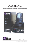
AutoRAE
Automated Bump Test And Calibration System
USER MANUAL
048-4002-000, Revision A, June 2005
! Warnings !
For safety reasons, this equipment must be operated and serviced by
qualified personnel only. Read and understand this manual and the
manuals accompanying any monitor(s) used with this unit completely
before operating or servicing.
! Operating Environment
This instrument has not been tested in an explosive gas/air atmosphere having
an oxygen concentration greater than 21%. Substitution of components may
impair intrinsic safety. Recharge batteries only in non-hazardous atmospheres.
! Computer Interface
Do not transfer data by means of the computer interface cable in hazardous
atmospheres.
! Static Hazard
Clean only with a damp cloth.
! Monitor Calibration
Any newly purchased RAE Systems instrument should be fully calibrated by
exposing it to known concentration calibration gases before the instrument is
put into service for the first time. For safety, check the accuracy of the monitor
by exposing the sensors to calibration gas(es) before each day’s use.
Contents
Introduction.............................................................................................2
AutoRAE Basic Setup Requirements .....................................................2
Setting Up The AutoRAE System ...........................................................3
Using The AutoRAE System...................................................................5
Charging Monitor Batteries................................................................5
Performing A Functional Bump Test ..................................................5
Calibrating A Monitor .........................................................................6
Calibrating And Bump Testing Multiple Monitors ...............................7
Disconnecting The AutoRAE System .....................................................7
Upgrading The AutoRAE Controller Firmware........................................8
SPECIAL NOTE: If the AutoRAE or a monitor needs to be serviced, contact
either:
The RAE Systems distributor where the EntryRAE or monitor was
purchased; they will return it on your behalf,
or
The RAE Systems Technical Service department. Before returning the
unit for service or repair, obtain a Returned Material Authorization (RMA)
number for proper tracking of your equipment. This number needs to be on
all documentation and posted on the outside of the box in which the unit is
returned for service or upgrade. Packages without RMA Numbers will be
refused at the factory.
1
Introduction
AutoRAE is an easy-to-use automatic bump test and calibration system
for RAE Systems’ gas detection and monitoring instruments. The
AutoRAE can perform the following functions:
• Charging monitors’ batteries.
• Simple bump test.1
• Full calibration of a five-sensor (O2, H2S, CO, LEL, PID) monitor.2
1. The bump test only verifies that sensors respond to gases. It is not
designed to fully validate all sensors in the monitor.
2. The O2 sensor is only calibrated with fresh air.
AutoRAE Basic Setup requirements
1. One AutoRAE controller.
2. One external power supply/cord.
3. At least one AutoRAE cradle.
4. Calibration gases with demand flow gas regulators (for example,
4-gas mix and Isobutylene for EntryRAE).
5. Monitor to be tested, charged, or calibrated.
6. Proper air ventilation setup/gas hood (not shown).
4. Demand
flow
regulators
4. Calibration
gas cylinders
5. Monitor to be
tested, charged,
or calibrated
2. External
power
supply
2
1. AutoRAE
controller
Ethernet
crossover cable
3. AutoRAE
cradle
Setting Up the AutoRAE System
1. Connect the power cord to the AutoRAE controller and plug it into an
external power supply.
2. Connect the AutoRAE cradles to the controller one at a time. Make
sure all connections are firm. It is not recommended that cradles be
connected to or disconnected from the AutoRAE controller while
the system is powered on. Note that poor connections between the
controller and cradle or between cradles can cause gas leaks. This
condition is indicated by the red “Leak” LED on the AutoRAE
controller.
LED Status
Indicators
Calibration
Leak
Ethernet
Communication
Power
3
Note: If more than one cradle is to be connected to the AutoRAE
controller, each cradle must be set with a different cradle unit ID ranging
from 0 to 9 (for a maximum of 10 cradles per AutoRAE controller).
This can be set with a screwdriver. Rotate the cradle until the ID dial on
the back is visible and turn the dial with the screwdriver. The order of
connection to the AutoRAE controller does not need to be sequential by
cradle unit ID.
Back of
cradle
ID dial
3. Connect the proper calibration gases to the AutoRAE controller gas
inlets. Note that each canister of gas should have a demand flow gas
regulator. The fresh air inlet should be left unconnected.
Calibration gas
inlets
4. Turn the AutoRAE controller
on using the power switch
on the back of the controller.
Check the status LEDs.
The red “Power” LED on
the controller will be lit,
and the green “Comm”
(communication) LED will
flash periodically.
4
Power
switch on
rear of
AutoRAE
controller
On the cradles, the “Start” button will flash for several seconds, and all
other cradle status LEDs will blink once. The cradle unit IDs will light
and remain lit as long as the system is powered on.
Cradle
unit ID
Calibration
fail LED
Charge
LED
Bump test LED
Calibration
LED
Start
button
Front of AutoRAE cradle.
Your AutoRAE system is now ready to use.
Using the AutoRAE System
The AutoRAE can be used to charge monitors’ batteries, perform
functional bump tests, and calibrate monitors.
Charging Monitor Batteries
1. Turn on the AutoRAE system.
2. Place the monitor to be charged into an AutoRAE cradle and check the
states of the cradle’s status LEDs. The green “Charge” LED will begin
flashing, and will continue to flash until the battery is fully charged.
Once the battery is fully charged, the LED will stop flashing and stay
lit. If the battery is fully charged when the monitor is placed into the
cradle, the “Charge” LED will still flash for several minutes.
Performing a Functional Bump Test
1. Turn the AutoRAE system on.
2. Place the monitor to be bump tested into an AutoRAE cradle. The
green “Charge” LED will begin flashing and the battery will begin to
charge.
3. Press the white “Start” button on the front of the cradle. The “Start”
5
button and green “Bump” LED will both begin to flash. You can
toggle between the “Bump” and “Cal” LEDs and no selection/cancel
while the “Start” button is flashing. The selected function’s LED (no
LED in the case of no selection/cancel) will flash at this time.
4. Select the bump test function (“Bump”). The “Start” button will stop
flashing after 10 seconds, and the current selection will be locked in.
The AutoRAE will then proceed to bump test the monitor. During
this time, the green “Cal/Bump” LED on the AutoRAE controller will
be lit, and the green “Bump” LED on the cradle will continue to flash
until the bump test is done (about 3 minutes). Upon completion of
the bump test, the “Bump” LED on the cradle will stop flashing and
remain lit is the monitor passed the test. The “Cal/Bump” LED on
the controller will also go out. If the monitor failed the bump test,
the AutoRAE will automatically start to calibrate the monitor (see
Calibrating a Monitor). After all functions have been performed, the
battery will resume charging.
Calibrating a Monitor
1. Turn on the AutoRAE system.
2. Place the monitor to be calibrated into an AutoRAE cradle. The green
“Charge” LED will begin flashing, and the battery will begin to charge.
3. Press the white “Start” button on the front of the cradle. The “Start”
button and green “Bump” LED will both begin to flash. You can
toggle between the “Bump” and “Cal” LEDs and no selection/cancel
while the “Start” button is flashing. The selected function’s LED will
flash at this time. Note: The LED does not flash in the case of no
selection/cancel).
4. Select the calibration function (“Cal”). The “Start” button will stop
flashing after 10 seconds, and the current selection will be locked
in. The AutoRAE will then proceed to calibrate the monitor. During
this time, the green “Cal/Bump” LED on the AutoRAE controller will
be lit, and the green “Cal” LED on the cradle will continue to flash
until the calibration is done (about 5 minutes). Upon completion of a
successful calibration, the “Cal” LED on the cradle will stop flashing
and remain lit. The “Cal/Bump” LED on the controller will also go
6
out. If the calibration failed, the red “Fail” LED on the cradle will be
lit. After all functions have been performed, the battery will resume
charging.
Calibrating and Bump Testing Multiple Monitors
The AutoRAE system will only bump test/calibrate one monitor at a
time. When multiple monitors are in AutoRAE cradles connected to
the AutoRAE controller, the AutoRAE will bump test/calibrate the
monitors in the order that they were selected. While the second through
last monitors are waiting to be tested/calibrated, the LED of the selected
function will flash and continue to flash until the bump test/calibration is
completed.
Disconnecting the AutoRAE System
You may disconnect cradles from the AutoRAE controller and from
each other by pressing the small rectangular button with a circle on top,
located on the top right of the cradle, and pulling the cradle away. It is
recommended that you connect and disconnect cradles only when the
AutoRAE controller is powered off.
Press button to
disconnect
Alignment
guide
Gas
connection
Side of AutoRAE cradle/controller.
Communication
connection
7
Upgrading the AutoRAE Controller Firmware
The firmware for the AutoRAE controller may be upgraded. To upgrade
the AutoRAE controller firmware, you will need:
1. Automatic firmware upgrade utility software (provided on the
AutoRAE Resource CD).
2. Ethernet crossover cable (provided in the AutoRAE package) .
3. Firmware file
Once you have collected these items, you may upgrade the AutoRAE
controller firmware by following these steps:
1. Connect the AutoRAE controller to your computer using the provided
Ethernet crossover cable. Insert one end of the cable into the
communication port on the side of the AutoRAE controller (shown
below). Insert the other end of the cable into the Ethernet port of
your computer.
Note: All other Ethernet connections (wired and wireless) on your
computer must be disconnected or disabled to use the automatic
upgrade utility.
Power adapter
connection
Side of AutoRAE controller.
Ethernet port
Ethernet
crossover
cable
2. Remove any instruments that may be in the AutoRAE cradles.
3. Turn on the AutoRAE controller.
8
4. Start the automatic firmware upgrade utility. The following window
will appear:
Information about your computer’s operating system is shown in the
lower left pane under Computer Information.
5. Start the upgrade process by selecting Operation > Upgrade
Firmware from the menu bar, or by pressing
(the upgrade
button). The following message will appear:
6. Click the Yes button to continue. Click the No button to cancel.
9
7. The utility will proceed to set up the connection between the
computer and the AutoRAE controller. During this time, the green
Ethernet LED on the AutoRAE controller will be lit and the
following message will appear:
If no connection is found within two minutes (120 seconds), the
utility will time out and return to the main window.
After the utility finishes setting up the connection, it will search for
the AutoRAE controller. During this time, the following screen will
appear:
8. Once the utility has found the AutoRAE controller, information about
the AutoRAE, such as firmware version, serial number, and the IP
address of the connection with the computer, will appear in the lower
right pane of the main utility window under AutoRAE Information.
A pop up window allowing you to select the AutoRAE firmware file
to upgrade to will also appear:
10
The utility will automatically select a firmware file. Ensure that this
is the correct firmware file. If it is not, click on the Browse button
and navigate to the appropriate file and click on the Open button:
9. Once the proper firmware file has been selected, press the OK button
on the Select Firmware Image window. If you do not want to
upgrade the firmware, press the Cancel button and the utility will
return to the main screen. The following warning will appear:
10. Click on the OK button to continue, or the Cancel button to abort.
The utility will prepare the connection between the computer and the
AutoRAE controller, and will then upgrade the firmware. During
this time, the green Ethernet LED on the front panel of the AUtoRAE
controller will light. A status bar will appear during the upgrade:
11
11. Once the firmware has been successfully upgraded, the following
message will appear:
Click on the OK button.
12. The utility will verify that the firmware was properly installed. The
verification progress window will appear:
13. Once the verification is complete, the following message will appear:
Press OK, and the utility will return to the main window.
14. To exit the utility, select Operations>Exit from the menu bar or click
on the (exit button).
12
15. To view information about the automatic upgrade utility program,
select Help>About from the menu bar or click on (help button).
Note: The Help>Power User Mode option in the menu bar is for factory
use only.
13
Thank you for reading this data sheet.
For pricing or for further information, please contact us at our UK Office, using the details
below.
UK Office
Keison Products,
P.O. Box 2124, Chelmsford, Essex, CM1 3UP, England.
Tel: +44 (0)1245 600560
Fax: +44 (0)1245 808399
Email: [email protected]
Please note - Product designs and specifications are subject to change without notice. The user is responsible for determining the
suitability of this product.