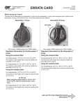
1
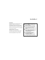
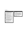
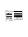
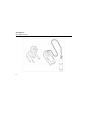
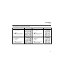
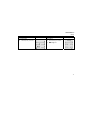
Non Printing line
GasAlertMicro 5
O2, CO, H2S, PH3, SO2, Cl2, NH3, NO2, HCN, ClO2, O3, VOC, and Combustibles
1, 2, 3, 4, and 5 Gas Detectors
Quick Reference Guide
D5614 English
iERP: 115696
© 2004 BW Technologies. All rights reserved. Printed in Canada.
All product names are trademarks of their respective companies.
11.500"
4.000"
Limited Warranty & Limitation of Liability
BW Technologies Ltd. (BW) warrants this product to be free from defects in material and workmanship under normal use and service for a
period of two years, beginning on the date of shipment to the buyer. This warranty extends only to the sale of new and unused products to
the original buyer. BW’s warranty obligation is limited, at BW’s option, to refund of the purchase price, repair, or replacement of a defective
product that is returned to a BW authorized service center within the warranty period. In no event shall BW’s liability hereunder exceed the
purchase price actually paid by the buyer for the Product. This warranty does not include:
a)
fuses, disposable batteries or the routine replacement of parts due to the normal wear and tear of the product arising from
use;
b)
any product which in BW’s opinion, has been misused, altered, neglected or damaged by accident or abnormal conditions of
operation, handling or use;
c)
any damage or defects attributable to repair of the product by any person other than an authorized dealer, or the installation
of unapproved parts on the product; or
The obligations set forth in this warranty are conditional on:
a)
proper storage, installation, calibration, use, maintenance and compliance with the product manual instructions and any other
applicable recommendations of BW;
b)
the buyer promptly notifying BW of any defect and, if required, promptly making the product available for correction. No
goods shall be returned to BW until receipt by the buyer of shipping instructions from BW; and
c)
the right of BW to require that the buyer provide proof of purchase such as the original invoice, bill of sale or packing slip to
establish that the product is within the warranty period.
THE BUYER AGREES THAT THIS WARRANTY IS THE BUYER’S SOLE AND EXCLUSIVE REMEDY AND IS IN LIEU OF ALL OTHER
WARRANTIES, EXPRESS OR IMPLIED, INCLUDING BUT NOT LIMITED TO ANY IMPLIED WARRANTY OF MERCHANTABILITY OR
FITNESS FOR A PARTICULAR PURPOSE. BW SHALL NOT BE LIABLE FOR ANY SPECIAL, INDIRECT, INCIDENTAL OR
CONSEQUENTIAL DAMAGES OR LOSSES, INCLUDING LOSS OF DATA, WHETHER ARISING FROM BREACH OF WARRANTY OR
BASED ON CONTRACT, TORT OR RELIANCE OR ANY OTHER THEORY.
Since some countries or states do not allow limitation of the term of an implied warranty, or exclusion or limitation of incidental or
consequential damages, the limitations and exclusions of this warranty may not apply to every buyer. If any provision of this warranty is
held invalid or unenforceable by a court of competent jurisdiction, such holding will not affect the validity or enforceability of any other
provision.
Contacting BW Technologies
1-888-749-8878 USA
1-800-663-4164 Canada
+44 (0) 1869 233004 Europe
+971-4-8871766 Middle East
+852-2974-1783 China
+65-9737-2005 South East Asia
+61-438-887-232 Australia
+1-403-248-9226 other countries
Visit BW Technologies’ web site at: www.gasmonitors.com
GasAlertMicro 5
Introduction
a Cautions
This quick reference guide provides basic information for the
GasAlertMicro 5. Refer to the user manual on the
accompanying CD-ROM for complete operating instructions.
The GasAlertMicro 5 gas detector (“the detector”) warns of
⇒
Warning: Substitution of components may
impair Intrinsic Safety.
⇒
Caution: For safety reasons, this equipment
must be operated and serviced by qualified
personnel only. Read and understand the user
manual completely before operating or
servicing.
⇒
Calibrate the detector before first-time use and
then on a regular schedule, depending on use
and sensor exposure to poisons and
contaminants. BW recommends at least once
every 180 days (6 months).
⇒
It is recommended that the combustible
sensor be checked with a known
concentration of calibration gas after any
known exposure to catalyst
contaminants/poisons (sulfur compounds,
silicon vapors, halogenated compounds, etc.).
hazardous gas at levels above user-selectable alarm setpoints.
The detector is a personal safety device. It is your responsibility
to respond properly to the alarm.
Safety Information - Read First
Use the detector only as specified in this guide, otherwise
the protection provided by the detector may be impaired.
Read the following Cautions before using the detector.
1
GasAlertMicro 5
Quick Reference Guide
⇒
2
BW recommends to “bump test” the sensors,
before each day’s use, to confirm their ability
to respond to gas by exposing the detector to
a gas concentration that exceeds the high
alarm setpoints. Manually verify that the
audible and visual alarms are activated.
Calibrate if the readings are not within the
specified limits.
⇒
Only the combustible gas detection portion of
this instrument has been assessed for
performance by CSA International.
⇒
The combustible sensor is factory calibrated
to 50% LEL Methane. If monitoring a different
combustible gas in the % LEL range, calibrate
the sensor using the appropriate gas.
⇒
Caution: High off-scale readings may indicate
an explosive concentration.
⇒
Protect the combustible sensor from exposure
to lead compounds, silicones, and chlorinated
hydrocarbons. Although certain organic
vapors (such as leaded gasoline and
halogenated hydrocarbons) may temporarily
inhibit sensor performance, in most cases, the
sensor will recover after calibration.
⇒
For use only in potentially explosive
atmospheres where Oxygen concentrations do
not exceed 20.9% (v/v).
⇒
Any rapid up-scaling reading followed by a
declining or erratic reading may indicate a gas
concentration beyond upper scale limit, which
may be hazardous.
⇒
Extended exposure of the GasAlertMicro 5 to
certain concentrations of combustible gases
and air may stress a detector element, which
can seriously affect its performance. If an
alarm occurs due to high concentration of
combustible gases, recalibration should be
performed, or if needed, the sensor replaced.
⇒
Electromagnetic interference may cause
incorrect operation under certain
circumstances.
GasAlertMicro 5
Parts of the GasAlertMicro 5
Parts of the GasAlertMicro 5
Item
Function
A
Visual alarm bars
B
Sensors
C
Audible alarm
D
Pushbuttons
E
Display
F
Battery pack
G
Alligator clip
3
GasAlertMicro 5
Quick Reference Guide
Display Elements
4
Item
Function
A
Alarm condition
B
Automatically span sensor
C
Gas cylinder
D
Gas identifier bars
E
Battery life indicator
F
Pass code lock
G
Data transmission (future use)
H
Clock
I
Stealth mode
J
Optional pump indicator
K
Optional datalogger card indicator
L
Alarm condition (low, high TWA, STEL, or
multi-gas) or view TWA, STEL, and maximum
gas exposures
M
Automatically zero sensor
GasAlertMicro 5
Pushbuttons
Pushbuttons
Pushbutton
A
Description
•
•
•
•
To turn on the detector, press A.
To turn off the detector, press A and hold until countdown is complete.
To increment the displayed value, press G.
To enter the user options menu, press G and H simultaneously and hold until countdown is
complete.
G
•
To clear the TWA, STEL, and maximum gas exposure readings, press C and G
simultaneously and hold until countdown is complete.
H
•
•
To decrement the displayed value, press H.
To initiate calibration and setting alarm setpoints, press C and H simultaneously and hold
until countdown is complete.
C
•
•
To view the TWA, STEL, and maximum (MAX) hold readings, press C.
To acknowledge latched alarms, press C.
5
GasAlertMicro 5
Quick Reference Guide
Install the Batteries
1.
2.
3.
6
Open the latch on the bottom of the detector and remove the battery pack by lifting up the end of the pack.
Remove the two screws on the battery pack, open the pack, and install the three alkaline batteries. Then replace the cover.
Insert the battery pack back into place and secure the latch.
GasAlertMicro 5
Calibration
Calibration
Procedure
Display
Procedure
1.
In a clean atmosphere, press and hold
C and H simultaneously (as the
detector beeps and flashes to the
corresponding countdown) to enter
calibration. The detector then reads
Starting calibration.
4.
Press H or G to change the next
calibration due date and press C to
accept this value. (If a sensor failed or
did not span, you cannot change the
calibration due date for that sensor.)
The display then advises to press C
to set or A to skip the alarm
setpoints.
2.
flashes while the detector
zeroes all of the sensors and
calibrates the Oxygen sensor. If a
sensor failed to auto zero, it will
bypass the span. Once auto zero is
complete, the display directs you to
either apply calibration gas to the
detector, or press A to skip the span.
5.
Press H or G to change the alarm
setpoint and press C to save the
displayed value and proceed to the
next setpoint. Set the remaining
setpoints. The detector beeps four
times at the end of the alarm setpoint
stage.
3.
K flashes when you connect the
6.
Saving calibration is displayed to
indicate that calibration is complete.
calibration bottle and apply gas at a
flow rate of 250-500 ml/min. If the
span is successful, press G to apply a
new cal-gas for another sensor, or H
to end the span. Once all sensors
have spanned, the display advises to
press C to set or A to skip the
calibration due dates.
Display
7
GasAlertMicro 5
Quick Reference Guide
Attaching the Calibration Bottle
8
GasAlertMicro 5
Alarms
Alarms
The following table lists the numerous alarms of the detector.
Alarm
Display
Alarm
Low Alarm:
TWA Alarm:
•
Fast modulating tone
•
Fast modulating tone
•
Slow flash
•
Slow flash
•
L and target gas bar flash
•
L and target gas bar flash
•
Vibrator alarm activates
•
Vibrator alarm activates
High Alarm:
STEL Alarm:
•
Constant tone
•
Constant tone
•
Fast flash
•
Fast flash
•
L and target gas bar flash
•
L and target gas bar flash
•
Vibrator alarm activates
•
Vibrator alarm activates
Display
9
GasAlertMicro 5
Quick Reference Guide
Alarm
Multi-Gas Alarm:
•
Alternating low and high alarm
tone and flash
•
•
Display
Alarm
Over Range Alarm:
(Over Level Exposure)
•
Fast modulating tone and flash
L and target gas bars flash
•
L and target gas bar flash
Vibrator alarm activates
•
Vibrator alarm activates
Sensor Alarm:
Automatic Shutdown Alarm:
•
Slow modulating tone and flash
•
8 beeps and flashes
•
L and gas bar(s) flash
•
•
Vibrator alarm activates
Vibrator alarm temporarily
activates
Low Battery Alarm:
(Confidence beep disabled)
•
•
10
1 beep and 1 flash every
10 seconds
flashes
Normal Shutdown:
•
3 beeps and flashes
•
Vibrator alarm temporarily
activates
Display
GasAlertMicro 5
Alarms
Alarm
Display
Alarm
Confidence Beep:
Pump Alarm:
•
•
Slow modulating tone and flash
•
L and J flash
2 fast beeps every 15 seconds
Display
11
GasAlertMicro 5
Quick Reference Guide
• Due-lock: Upon startup, it prevents the user from
User Options Menu
operating a detector that is overdue for calibration by
To access the user options menu press and hold G and H
requesting a pass code;
until the detector completes the countdown.
• Latch: This option allows an alarm to remain active
until the user acknowledges the alarm;
To scroll through the options, press H or G. Press C to
• Passcode: Prevents unauthorized personnel from
select the option. The following are the available user options:
1.
Exit: Exits the user options menu.
2.
Language: Enables the display’s language in the user’s
having access to the user options menu, calibration
function, and alarm setpoint adjust function.
• Safe: Enables the display to read Safe if the detector
choice of English, French, Spanish, German, or
does not enter an alarm;
Portuguese.
3.
Options:
• Backlght: Enables the backlight in low-light
conditions;
• Confibeep: Enables/disables the confidence beep;
• Force Cal: Forces the detector into mandatory
calibration if a sensor is overdue for calibration upon
startup;
12
• Stealth: Enables vibrator signaling only.
4.
Sensors:
• Sens on: Enables/disables the sensor (the detector
still operates if a sensor is disabled);
• Span gas: Changes the span gas concentration for
each sensor;
• STEL period: Changes the short-term exposure limit
(only applicable to toxic sensors);
GasAlertMicro 5
Maintenance
• TWA method: Choose either the OSHA or ACGIH
standard of calculating the time-weighted average;
• Correction: Allows the user to adjust the instrument
reading for a specific combustible gas (only
applicable to LEL and PID sensors);
Maintenance
To keep the detector in good operating condition, perform
the following basic maintenance as required:
•
applicable);
•
• % vol CH4: Shows the LEL reading in % vol.
assuming a Methane environment;
• Auto-cal: Automatic Oxygen calibration upon startup.
5.
6.
Logger: Allows the user to change the datalogging
Calibrate, bump check, and inspect the detector at
regular intervals.
• Precision: Sets the accuracy of the gas reading (if
Keep an operations log of all maintenance, bump
checks, calibrations, and alarm events.
•
Clean the exterior with a soft damp cloth. Do not use
solvents, soaps, or polishes.
Do not immerse the detector in liquids.
interval (between 5-120 seconds).
•
Clock: Allows the user to set the date and time for the
Photoionization Detector (PID) Sensor
detector.
Clean the Lamp
The PID lamp needs to be cleaned (with a cleaning kit) in the
following situations:
•
When the PID reading creeps upward after the sensor is
zeroed;
•
When any movement of the detector changes the PID
reading.
13
GasAlertMicro 5
Quick Reference Guide
3.
Parts of the PID Sensor
Item
Function
A
Sensor
cover
B
Electrode
stack
C
Diffusion
barrier
D
Lamp
E
PID
sensor
Place some Methanol on the end of a cotton-tipped stick
before using it to clean the lamp.
4.
Once clean, reassemble the sensor.
Replace the Electrode Stack
Replace the electrode stack when it is contaminated.
1.
Remove the sensor cover.
2.
Remove the old electrode stack.
3.
Install the new electrode stack in its place.
Note
Ensure your fingers do not make contact with the diffusion
barrier and the electrodes on the underside of the stack.
a Caution
Never handle the lamp with your bare hands.
1.
Place finger covers on your fingers.
2.
Take apart the sensor to remove the lamp.
14
4.
Replace the sensor cover.
GasAlertMicro 5
Specifications
Replace the Lamp
Replace the lamp when it falls below the acceptable level.
1.
2.
Remove the old lamp from the PID.
Ensure finger covers are on before inserting the new
lamp into the PID shell.
3.
Reassemble the sensor.
Specifications
Instrument dimensions: 14.5 x 7.4 x 3.8 cm
(5.7 x 2.9 x 1.5 in.)
Weight: 300 g (10.6 oz.)
Operating temperature:
VOC: -10°C to +40°C (14°F to +104°F)
Other gases: -20°C to +50°C (-4°F to +122°F)
Storage temperature: -20°C to +50°C (-4°F to +122°F)
Operating humidity:
O2: 0% to 99% relative humidity (non-condensing)
VOC: 0% to 95% relative humidity (non-condensing)
Cl2: 10% to 95% relative humidity (non-condensing)
HCN, ClO2: 15% to 95% relative humidity (non-condensing)
Other gases: 15% to 90% relative humidity (non-condensing)
Operating pressure: 95 to 110 kPa
Detection range:
O2: 0 – 30.0% vol. (0.1% vol. increments)
CO: 0 – 999 ppm (1 ppm increments)
H2S: 0 – 100 ppm (1 ppm increments)
PH3: 0 – 5.0 ppm (0.1 ppm increments)
SO2: 0 – 100 ppm (1 ppm increments)
Cl2: 0 – 50.0 ppm (0.1 ppm increments)
NH3: 0 – 100 ppm (1 ppm increments)
NO2: 0 – 99.9 ppm (0.1 ppm increments)
HCN: 0 – 30.0 ppm (0.1 ppm increments)
ClO2: 0 – 1.00 ppm (0.01 ppm increments)
O3: 0 – 1.00 ppm (0.01 ppm increments)
VOC: 0-1000 (5.0 ppm increments)
Sensor type:
H2S/CO: Twin plug-in electrochemical cell
Combustibles: Plug-in catalytic bead
VOC: Photoionization detector (PID)
Other gases: Single plug-in electrochemical cell
O2 measuring principle: Capillary controlled concentration
sensor
Alarm conditions: TWA alarm, STEL alarm, low alarm, high
alarm, multi-gas alarm, sensor alarm, pump alarm, low battery
alarm, confidence beep, automatic shutdown alarm
Audible alarm: 95 dB at 1 ft (0.3 m) variable pulsed dual
beepers
Visual alarm: Dual red light-emitting diodes (LED)
Display: Alphanumeric liquid crystal display (LCD)
Alarm setpoints: May vary by region and are user-settable
15
GasAlertMicro 5
Quick Reference Guide
Backlight: Automatically activates whenever there is
insufficient light to view the display (if enabled) and during
alarm conditions
Self-test: Initiated at activation
Calibration: Automatic zero and automatic span
Oxygen sensor: Automatic span on activation (selectable)
User field options: Confidence beep, latching low and high
alarms, pass code protection, enable/display Safe display
mode combustible sensor measurement, sensor disable, set
calibration due date, TWA and STEL, stealth mode, language
selection, enable/disable automatic Oxygen calibration, set
span concentration values, set STEL calculation period, set
TWA method, enable/disable automatic backlight, adjust clock
calendar, and set logging rate (datalogger models only).
Battery operating time:
Given that detector is operating with an LEL and PID sensor
and the optional pump:
3 alkaline cells: 8-10 hours
1 rechargeable NiMH pack: 14-16 hours
16
Approved batteries:
North America
Approved batteries for product (standards EN50020, UL913,
C22.2 No. 157)
Alkaline:
Temperature Code
Duracell MN1500
-20°C ≤ to ≤ 50°C (139.8°C)
Energizer E91
-20°C ≤ to ≤ 50°C (163°C)
Duracell MN1500
-20°C ≤ to ≤ 40°C (129.8°C)
Energizer E91
-20°C ≤ to ≤ 40°C (153°C)
NiMH rechargeable:
Sanyo HR-3U
Battery charger: GasAlertMicro 5 battery charger
First-time charge: 4 hours per battery pack
Normal charge: 3-4 hours per battery pack
Approvals: Intrinsic safety certifications in progress
Thank you for reading this data sheet.
For pricing or for further information, please contact us at our UK Office, using the details
below.
UK Office
Keison Products,
P.O. Box 2124, Chelmsford, Essex, CM1 3UP, England.
Tel: +44 (0)1245 600560
Fax: +44 (0)1245 808399
Email: [email protected]
Please note - Product designs and specifications are subject to change without notice. The user is responsible for determining the
suitability of this product.