1
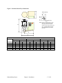
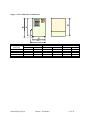
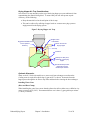
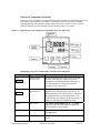
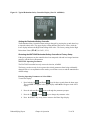
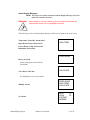
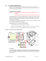
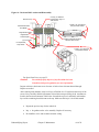
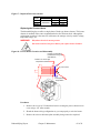
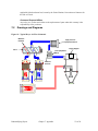
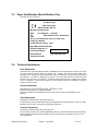
Figure 16: Desiccant Bed Location and Disassembly
Undo (4) 10-32 Button
Head Screws using 1/8
Allen Wrench
Desiccant Cap
1" Wide x 1/8" Thick Silicon
Strip and Stick Gasket
13X Molecular Sieve
8x12 Beads
Regeneration Heater
Regeneration
Thermocouple
16 Mesh 0.028 Diameter Wire
Stainless Steel Screen
(2) 4-40 screws
Hi Temperature
Snap Switch
1" Wide x 1/8" Thick High
Temperature Gasket
For Spare Parts Lists, see page 55.
Caution!
You should properly dispose of any discarded desiccant.
Consult local disposal regulations for more information.
Inspect each lower desiccant screen for tears or holes where desiccant burned-through.
Replace as needed.
After cleaning each chamber, add a level layer of half the 8 x 12 bead desiccant on top of the
screen. Next, carefully add the full amount of bead desiccant specified per bed. Amounts are
listed in the Desiccant Amounts Table below. Smooth the top level, and finally add another
layer of the remaining bead desiccant to the top. Make sure this layer is level and smooth.
•
Repeat the previous step for the other bed.
•
Inspect the gaskets on the valve assembly. Replace if necessary.
•
Re-install the valve and reconnect actuator wiring.
Dehumidifying Dryers
Chapter 5: Maintenance
44 of 58