1
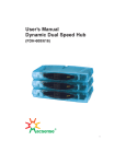
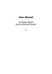
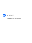
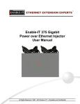
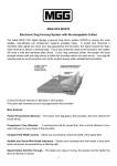
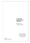
User Manual
Industrial Fast Ethernet 8 port Ethernet Switch, Power input 12-56VDC, -40°C to 75°C
FCC MARKING
This Equipment has been tested and found to comply with the limits for
a Class A digital device, pursuant to part 15 of the FCC Rules. These
limits are designed to provide reasonable protection against harmful
interference when the equipment is operated in a commercial
environment. This equipment generates, uses, and can radiate radio
frequency energy and, if not installed and used in accordance with the
instruction manual, may cause harmful interference to radio
communications.
Operation of this equipment in a residential area is likely to cause
harmful interference in which case the user will be required to correct
the interference at his own expense.
This device complies with Part 15 of the FCC Rules. Operation is subject
to the following two conditions: (1) this device may not cause harmful
interference, and (2) this device must accept any interference received;
including interference that may cause undesired operation.
CE MARKING
This equipment complies with the requirements re lating to
electromagnetic compatibility, EN 55022 class A for ITE, the essential
protection requirement of Council Directive 2004/108/EC on the
approximation of the laws of the Member States relating to
electromagnetic compatibility.
Company has an on-going policy of upgrading its products and it may
be possible that information in this document is not up -to-date. Please
check with your local distributors for the latest information. No part of
this document can be copied or reproduced in any form without w ritten
consent from the company.
Trademarks:
All trade names and trademarks are the properties of their
respective companies.
Copyright © 2013, All Rights Reserved.
1
Installation package
This unit can be installed by din-rail mounted or wall-mounted. Din-rail brackets and wallmounted bracket are included.
Din Rail Bracket x 1
6 pin Terminal Block x1
Wall mount bracket x 2
Power connection
This
industrial
Fast Ethernet
switch
comes
with
a 6 pin
terminal
block.
It can voltage
be operated
12-56VDC
power
source.
Always
Makeinput
sure
your
input
voltage
is within
this
supported
rangefrom
for
model.
WARNING
– any
exceeded
voltage
will
not
make
this unit
function
and
may
damage
thiseach
unit.
To
make
power
connection
– Follow
the
printed
polarity
for
V1+,
V1-,
V2+,
V2-,
and
ground.
Connect
positive
wire
to to
V+
, screw
connect
wire
to
V-,
also
connect
neutral
wire
to
the
ground
as negative
shown
.
Relay
-You
may
use
24V@1A
relay
connection
your
external
device
for special
purpose.
2 powers
arefails,
connected,
the
relay
is
OPEN
mode.
When When
any power
source
the relay
change
toin
SHORT
status.
STEP
1
–
Pull
out
6
pin
terminal
block.
Power
connecting
procedure:
2
Connect
wire
to
V1+,
V1-,
or
V2+,
V2-,
and
Ground
the
neutral
wire
to
the
ground
screw.
STEP
3–
Plug
back
6
pin
terminal
block
to
its
place.
WARNING –
Always ground the power source to maintain a clean power input. Due to too many cheap
made power supplies, it creates too much noise, and it will cause the power input fluctuates
when connect to this unit. To avoid this, always ground the power source to gain a clean
power input.
2
LED indicator
PW1
ON -- when V1+, V1- is connected
PW2
ON -- when V2+, V2- is connected
This unit has no POE feature. the POE amber
LED will always stays in OFF status.
Green LED --ON =Link
Flash = TX/RX.
Relay LED Amber
ON one power is connected
OFF two powers are connected
3
Specification:
IEEE Standard
Switch Architecture
Data Processing
Flow Control:
MAC address Table Size
Packet Buffer Size
Network Connector :
Network Cable
Protocol
LED
IEEE 802.3 10Base-T Ethernet
IEEE 802.3u 100Base-TX Fast Ethernet
IEEE802.3x Flow Control and Back Pressure
Back-plane (Switching Fabric): 1.6Gbps
Store and Forward
IEEE 802.3x Flow Control and Back Pressure
1K
1M
8xRJ-45 10/100BaseT(X) auto negotiation,
Auto MDI/MDI-X function, Full/Half duplex
UTP/STP above Cat.5e Cable
EIA/TIA-568 10-ohm (100m)
CSMA/CD
PW1(Power 1) Green,
PW2(Power 2) Green,
SW(relay) Amber,
TX/RJ-45 port:
LNK (Link/Active) Green,
Housing
Heavy Metal Housing
Reserve polarity protection
Overload current protection
Present
Power Supply
Redundant Dual DC 12V-56V Power Input
Power Consumption
3W@48 VDC full load,
Present
4
Alarm Relay Contact
POE power
Removable Terminal Block
Relay outputs with current carrying capacity of 1 A
@24VDC,
Relay in short circuit mode when 2 powers are
connected. in open circuit mode when only one
power supply is connected
n/a
Provide 2 Redundant power , Alarm relay contact ,6
Pin
Wire range: 0.34mm^2 to 2.5mm^2
Solid wire (AWG):12-24/14-22
Stranded wire(AWG): 12-24/14-22
Torque:5lb-In/0.5Nm/0.56Nm
Wire Strip length: 7-8mm
Operating Temperature
-40℃~75℃ fully tested.
Operating Humidity
5% to 95% (Non-condensing)
Storage Temperature
-40℃~85℃
MTBF (mean time between
failure)
Housing
Case Dimension (L x W x D)
Installation mounting
510,304 hrs ( MIL-HDBK-217F) at 25°C
Rugged Metal ,IP30 Protection
142mmx36.2mmx105mm (LxWxD)
DIN Rail mounting and Wall Mounting
Certifications:
EN55022/24
EN55011
Safety
EMC/EMS
EMI
EN 50155 / EN 60068-2-6
EN 50155 / EN 60068-2-27
EN 50155 / EN 60068-2-32
ITE equipment
Industrial, Scientific and Medical (ISM) equipment
IEC EN60950-1
CE, FCC, VCCI
FCC Part 15 Subpart B Class A,
CE EN 55022 Class A
Vibration
Shock
Free Fall
5
Housing Dimension
6