1
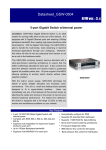
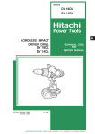
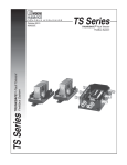
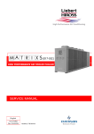
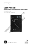
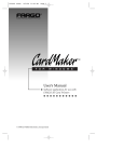
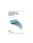
User’s Manual
Dynamic Dual Speed Hub
(FDH-608/616)
acsense
R
1
Contents
Introduction . . . . . . . . . . . . . . . . . . . . . . . . . . . . . . . . . . . . . . . .II
Quick Installation . . . . . . . . . . . . . . . . . . . . . . . . . . . . . . . . . . .III
Chapter 1 - General Features of a Hub . . . . . . . . . . . . . . . . . .1
General Features . . . . . . . . . .
Front Panel . . . . . . . . . . . . . .
Rear Panel . . . . . . . . . . . . . .
Cost Effective Stackable Hubs
.
.
.
.
.
.
.
.
.
.
.
.
.
.
.
.
.
.
.
.
.
.
.
.
.
.
.
.
.
.
.
.
.
.
.
.
.
.
.
.
.
.
.
.
.
.
.
.
.
.
.
.
.
.
.
.
.
.
.
.
.
.
.
.
.
.
.
.
.
.
.
.
.
.
.
.
.
.
.
.
.
.
.
.
.
.
.
.
.
.
.
.
.
.
.
.
.
.
.
.
.
.
.
.
.
.
.
.
.
.
.
.
.
.
.
.
.1
.2
.2
.3
Chapter 2 - A Quick Overview of Networking
Terminology . . . . . . . . . . . . . . . . . . . . . . . . . . . . . .5
Network Terminology . . . . . . . . . . . . . . . . . . . . . . . . . . . . . . . . . . . . .5
What is a hub? . . . . . . . . . . . . . . . . . . . . . . . . . . . . . . . . . . . . . . . . .5
Chapter 3 - What Is Fast Ethernet? . . . . . . . . . . . . . . . . . . . . .7
Historical Background . . . . . . . . . . . . . . . . . . . . . . . . . . . . . . . . . . . .7
Ethernet and Fast Ethernet Standards . . . . . . . . . . . . . . . . . . . . . . . .7
Cables Required . . . . . . . . . . . . . . . . . . . . . . . . . . . . . . . . . . . . . . . .7
Chapter 4 - How to Configure a Fast Ethernet
Network . . . . . . . . . . . . . . . . . . . . . . . . . . . . . . . . .9
Cable Length . . . . . . . . . . . . . . . . . . . . . . . . . . . . . . . . . . . . . . . . . . .9
Uplinking . . . . . . . . . . . . . . . . . . . . . . . . . . . . . . . . . . . . . . . . . . . . . .9
Different Network Topologies . . . . . . . . . . . . . . . . . . . . . . . . . . . . . .10
Other Ways to Expand a Network . . . . . . . . . . . . . . . . . . . . . . . . . .11
Chapter 5 - How to Install a Hub . . . . . . . . . . . . . . . . . . . . . .13
Before the Installation . . . . . . . . . . . . . . . . . . . . . . . . . . . . . . . . . . .13
Physical Installation . . . . . . . . . . . . . . . . . . . . . . . . . . . . . . . . . . . . .14
Connecting Hubs or Other Devices . . . . . . . . . . . . . . . . . . . . . . . . .15
Stacking the Dual-Speed Hub . . . . . . . . . . . . . . . . . . . . . . . . . . . . .16
Removing the Protective Cover . . . . . . . . . . . . . . . . . . . . . . . . . . . .17
Cable Connections . . . . . . . . . . . . . . . . . . . . . . . . . . . . . . . . . . . . .18
Checking Port Status . . . . . . . . . . . . . . . . . . . . . . . . . . . . . . . . . . . .19
Chapter 6 - Network Management . . . . . . . . . . . . . . . . . . . . .21
LED Indicators . . . . . . . . . . . . . . . . . . . . . . . . . . . . . . . . . . . . . . . . .21
Troubleshooting . . . . . . . . . . . . . . . . . . . . . . . . . . . . . . . . . . . . . . . .22
Specifications . . . . . . . . . . . . . . . . . . . . . . . . . . . . . . . . . . . . .25
Specifications of FDH-608 . . . . . . . . . . . . . . . . . . . . . . . . . . . . . . . .25
Specifications of FDH-616 . . . . . . . . . . . . . . . . . . . . . . . . . . . . . . . .25
I
Introduction
Congratulations on your purchase of this Fast Ethernet Dual-Speed Hub!!
The Fast Ethernet Dual-Speed Hub consists of 8XRJ-45 ports for 10Mbps or
100Mbps Ethernet connection (determined by autosensing). This Dual-Speed hub
contains two internal repeaters - one for 10Mbps and another for 100Mbps traffic.
An internal Ethernet switch, consisting of a 10Mbps and a 100Mbps switching port,
is used to link the repeater buses. Data will be forwarded to the other internal
repeater bus under these three conditions: 1) when traffic has to be passed
between a 10Mbps and a 100Mbps device; 2) if the destination address is not
found in the address table; 3) when broadcast traffic is sent.
This hub is capable of storing the node address and the corresponding segment of each incoming packet in a routing table. The information on this routing
table helps to identify the traffic and directs fast (100BASE-TX) or slow (10BASEtraffic to the proper repeater buses. By separating the two repeater buses into different collision domains, the overall collisions that might occur are reduced relative
to the number that might occur if two traffic flows were to coexist in a singular collision domain.
Migration from 10Mbps Ethernet to 100Mbps Fast Ethernet environment usually
involves total abandonment of 10Mbps equipment and requires replacing upgrading to 100Mbps equipment. In contrast, Dual-Speed Hubs allow gradual migration
from one speed to another without throwing out 10Mbps network hardware.
This manual will introduce you to the main features of your hub, as well offer as
a brief introduction on networking terminology and topography. Tips for installation
and for everyday management of your network (including troubleshooting) are also
included to help you get started.
II
Quick installation
This hub provides an ideal bridge between 10Mbps and 100Mbps Ethernet networks, all for a price thatÕs comparable to a standard Ethernet or Fast Ethernet
hub. Moreover, the smart design built into the display panel provides a friendly
interface that simplifies installation and network troubleshooting. If you are already
familiar with basic network operations, you should be able to install this hub by following these steps:
1.
Unpack the Fast Ethernet Dual-Speed Hub.
2.
Find a location near an electrical outlet.
3.
Set the Hub on a stable horizontal surface that is clear of electromagnetic interference. Make sure to turn the power off of the hub and any
other device that will be connected while installing network components.
4.
Connect PCs or other network devices to the RJ-45 ports using
Category 5 UTP (UTP-5), Category 1 STP (STP-1) for 100BASE-TX, or
Category 3, 4, 5 UTP (UTP-3, 4, 5), Category 1 STP (STP-1), or equivalent cables for 10BASE-T. We recommend starting from the highestnumbered jack. All devices that will be connected to the hub have to be
equipped with Fast Ethernet adapters. The maximum cable length
between any end node in the network and the hub is 100 meters (328
feet) for Fast Ethernet.
5.
Turn the power on the Fast Ethernet Dual-Speed Hub and all PCs and
network devices.
6.
Verify network communication by observing the LED activities of power,
connection speed, and each individual nodes. The hub will indicate connections of ports by blinking the corresponding port indicator LEDs.
If problems arises while installing this Dual-Speed Hub, please refer to the
ÒInstallation ChapterÓ for more information of installation procedures, the ÒUplink
ChapterÓ for strategies on connecting networking devices together, or ÒTrouble
ShootingÓ for further references.
III
General Features of a Dual-Speed Hub
Chapter 1 - General Features of a Dual-Speed Hub
General Features of FDH-608 8-Port Dual-Speed Stackable Hub
Compliant with the IEEE802.3 10Mbps repeater specification (10BASE-T)
Compliant with the IEEE802.3u 100Mbps repeater specification (100BASE-TX)
8-port 10BASE-T for Ethernet connectivity
Supports Category 3, 4, 5 Unshielded Twisted-pair cabling (UTP-3,4,5)
Supports Category 1 Shielded Twisted-pair cabling (STP-1)
8-port 100BASE-TX for Fast Ethernet connectivity
Supports Category 5 Unshielded Twisted-pair cabling (UTP-5)
Supports Category 1 Shielded Twisted-pair cabling (STP-1)
One uplink port on the rear panel for connectivity to another Switch/Repeater hub
Individual port status LEDs for LINK, RX, 10/100, PAR and 10/100 Collision status
LEDs
General Features of FDH-616 16-Port Dual-Speed Stackable Hub
Compliant with the IEEE802.3 10Mbps repeater specification (10BASE-T)
Compliant with the IEEE802.3u 100Mbps repeater specification (100BASE-TX)
16-port 10BASE-T for Ethernet connectivity
Supports Category 3, 4, 5 Unshielded Twisted-pair cabling (UTP-3,4,5)
Supports Category 1 Shielded Twisted-pair cabling (STP-1) 16-port
16-port 100BASE-TX for Fast Ethernet connectivity
Supports Category 5 Unshielded Twisted-pair cabling (UTP-5)
Supports Category 1 Shielded Twisted-pair cabling (STP-1)
One uplink port on the rear panel connectivity to another Switch/Repeater hub
Individual port status LEDs for LINK/ACTIVITY and Collision status LEDs
1
Chapter 1 - continued
Front panel
FDH-608
5
100M
COL
PWR
10M 100M
LK
PART 100M
RX
RX
LK
1
LK
RX
RX
RX
PART
LK
RX
3
PART 100M
LK
8
PART 100M
LK
2
PART 100M
100M
7
6
PART 100M
4
PART 100M
LK
RX
PART
LK
RX
FDH-616
5
PWR
10M 100M
LK
RX
LK
PART 100M
LK
1
100M
7
6
PART 100M
100M
COL
RX
PART 100M
RX
LK
8
PART 100M
LK
2
RX
PART 100M
RX
LK
PART
LK
3
RX
4
PART 100M
RX
LK
PART
RX
The Dual-Speed hubÕs front panel display features LED (light emitting diode)
indicators
Rear panel
FDH-608
8
7
6
5
4
3
2
1
1X
FDH-616
The rear panel of the hub contains the power socket and Ethernet cable connectors. The hub's cable connectors are RJ-45 type cable jacks. RJ-45 stands for
Recommended Jack No. 45, an Electronic Industries Association (EIA) designation.
Each jack serves to connect a cable to the network device.
The jack label 1X is designated as an uplink jack. Uplink jacks are designed
for connections to other network devices.
2
General Features of a Dual-Speed Hub
NOTE: The jack adjacent to 1X must never be used at the same time.
LED indicators allow users to check each port's status and network traffic at a
glance. Extensive LEDs are displayed on the hub to allow easy network management.
The power socket accepts AC power of 115~230V at 50~60 Hz.
Cost-Effective Stackable Hubs
These Dual-Speed Stackable Hubs provide the quickest method of upgrading
your network to Fast Ethernet. There's no need to replace an existing network
infrastructure. Just add a Dual-Speed hub to link any new Fast Ethernet devices
into your current network. These Dual-Speed hubs bring you the immediate performance advantages of Fast Ethernet at an incremental cost. WhatÕs more, these
stackable hubs break Fast Ethernet's two-hub cascade barrier, allowing you to link
up to three hubs via the built-in stack ports (using any combination of these hub
models).
These Dual-Speed Hubs provide an effective solution for expanding Ethernet
and Fast Ethernet networks at a modest price. Up to three units can be stacked
together, supporting up to 24 (8-Port Fast Ethernet Dual-Speed Hub) or 48 users
(16-Port Fast Ethernet Dual-Speed Hub). To interconnect the 10 Mbps and
100Mbps segments, just add an FDH-608 or FDH-616 unit to the stack. However,
a single Fast Ethernet Dual-Speed Hub stack of only two units can easily meet the
networking needs of most small to medium-sized workgroups. As your workgroups
gradually expand, just add more hubs to your stack, or uplink to another hub or
switch using ordinary straight-through cable.
3
A Quick Overview of Networking Terminology
Chapter 2 - A Quick Overview of Networking Terminology
Network Terminology
A network is comprised of multiple interconnected nodes. A node can be a
computer, a server (that is, a computer dedicated to storing network data or applications), a shared peripheral (such as a printer or modem) or other networking
devices (such as repeaters or switches, routers, transceivers, etc.).
A Fast Ethernet network operates at a 100Mbps (Megabits per second) transfer
speed, as opposed to Ethernet networks, which operate at speeds of 10Mbps.
To be connected to a Fast Ethernet network, a node must be equipped with a
Fast Ethernet adapter or a network interface card (NIC). A twisted-pair cable connects the node to a hub. Each node is connected to one port on the hub. The port
possesses the abilities of a repeater, a transceiver and an adapter in a Fast
Ethernet network. Ports and cables are connected through a fixed jack.
Multiple segments can be connected by repeaters. All segments connect
together through switches (but not by routers, or bridges) to form a collision
domain.
Collisions occur when two or more nodes accidentally attempt to transmit data
across the network at the same time. This happens more often with increased traffic. Naturally, when you have more packets traveling across the network, the occurrence of collisions will increase. Although collisions do not cause any serious
harm, they can affect the speed at which all nodes on the network receive data.
Moreover, collisions prohibit twisted-pair cabling from being fully utilized, since one
of the cableÕs two twisted pairs must resolve collision conflicts instead of transmitting data.
What is a Hub?
In data communications, a hub is a place of convergence where data arrives
from one or more directions and is forwarded out in one or more other directions.
A port is comprised of an input/output circuit and any associated circuit. A jack,
on the other hand, is an external connector linked to a port. According to a hubÕs
design, one or more jacks can be connected to a single port.
Your hub displays different jacks on its external panel. One or more jacks are
connected to one internal port. The uplink jack features two jacks. One of them
acts as a regular port for data transferring while the other (X) serves to uplink the
5
Chapter 2 - continued
hub to another hub or switch. By uplinking different hubs or switches together, the
number of nodes in a network can be increased. Expanding a network is necessary when planning to increase the number of computers connected, or when planning to offer new services, such as printing capabilities or Internet access.
Each port of a Dual-Speed Hub acts as an adapter (to conform to the network
environment), a transceiver (to carry data) and a repeater (to connect different segments together).
Four standard functions are performed by a Dual-Speed Stackable Hub:
- Repeating any signal that it receives from a connected node to another designated node by referencing the physical address number in the Address
Table.
- Checking the validity of each signal it receives and discarding invalid signals.
- Checking for collisions on the network and partitioning the collisioned nodes
to prevent further disruption of the network.
- Showing whether each network node is currently connected and idle, transmitting data, or in 10BASE-T/100BASE-TX mode.
However, according to the type of device that is connected to a hub, different
applications are supported. Typical applications performed by a hub are:
- Establishing peer-to-peer relations between workstations.
- Interconnecting users' workstations with a server for a stand-alone clientserver network.
- Interconnecting different users' workstations, servers, or other devices, and
uplinking with another Fast Ethernet Dual-Speed hub to form a larger network.
- Interconnecting different users' workstations or servers, or uplinking the hub
with another network device and providing a connection with another network
expansion device, such as a router, switch or bridge.
A hub thus acts as a central piece in a network topology and configuration. It is
necessary to carefully study its physical placement within the configuration of the
network for maximum efficiency.
6
What Is Fast Ethernet?
Chapter 3 - What is Fast Ethernet?
Historical Background
Fast Ethernet was developed in the early nineties as an answer to the bottlenecking problems encountered by older Ethernet networks. Ethernet is a networking technology that was developed in the early seventies.
Ethernet networks carried data signals through thick passive cables at a
10Mbps speed. However, signals were delivered to all nodes in the network at the
same time, which resulted in frequent collisions and a lag in general network performance.
Fast Ethernet, in contrast, transmits data at a rate of 100Mbps. This performance boost is needed for users of CAD/CAM applications, videoconferencing,
and the exchange of large files.
Apart from increasing available bandwidth, Fast Ethernet systems also bring
the advantage of using the same network operating system as do Ethernet networks. Moreover, it is backwards compatible with Ethernet equipment.
Ethernet and Fast Ethernet Standards
Standards for Ethernet and Fast Ethernet systems are issued by the Institute of
Electrical and Electronic Engineers (IEEE). The standard for Ethernet twisted-pair
networks is known as the IEEE802.3 standard, or 10BASE-T.
Its successor, Fast Ethernet, is governed by the IEEE802.3u standard or
100BASE-TX. Your hub complies with the 100BASE-TX standard.
To set up a network with a Fast Ethernet Dual-Speed Hub, all nodes have to be
connected to the hub through 10BASE-T/100BASE-TX compliant adapters (built-in
or plug-in versions) or network interface cards (NIC).
As for the network operating system, any Ethernet-compatible system can be
used as well as NICs' drivers.
Cable Required
Twisted-pair cabling is ordinary copper wire that connects home and (some)
business computers to the network. To reduce crosstalk or electromagnetic induction between pairs of wires, two insulated copper wires are twisted around each
other. Each signal on twisted-pair wiring requires both wires. For some business
locations, the twisted-pair is enclosed in a shield that functions as a ground. This is
7
Chapter 3 - continued
known as a shielded twisted-pair (STP). Ordinary wire to the home is unshielded twisted-pair (UTP).
Use unshielded twisted-pair (UTP) or shielded twisted-pair (STP) cable for
Ethernet and Fast Ethernet networks.
10BASE-T :
requires Category 3, 4, 5 unshielded twisted-pair
(UTP-3, 4, 5) or Category 1 shielded twisted-pair (STP-1),
or any equivalent cable to transmit data.
100BASE-TX :
requires Category 5 unshielded twisted-pair (UTP-5) or
Category 1 shielded twisted-pair (STP-1), or any equivalent cable to transmit data.
Either UTP-5, STP-1 or equivalent cable must be used with a Fast Ethernet.
Those cables are easy to find as they are widely sold in retail stores and are preinstalled in many buildings.
8
How to Configure a Fast Ethernet Network
Chapter 4 - How to Configure a Fast Ethernet Network
Cable Length
In a Fast Ethernet network, twisted-pair cables have a length limit. No UTP or
STP cable can be more than 100 meters (328 feet) long. A signal cannot be sent
between two end nodes through more than 200 meters of twisted-pair cable.
In a non-uplinked network, all end nodes are thus connected to a hub through
cables that do not exceed 100 meters (328 feet) in length.
For this reason, a non-uplinked network is said to have a maximum diameter of
200 meters (656 feet), as a signal first sent from one end node to the hub where it
is then re-broadcast to another end node.
When configuring a network, users must pay attention to each cable, ensuring
that no cable exceeds the length limit and that this length is well-managed between
end nodes and the hub.
Uplinking
Uplinking a hub with another network expansion device, such as a router,
switch, bridge, or repeater hub allows users to increase the number of ports on a
network. A 100BASE-TX hub can be uplinked with another 10BASE-TX/100BASETX hub through a twisted-pair cable. This is an easy and inexpensive way to
increase the number of interconnected nodes on a network.
Uplinking hubs, however, adds additional network constraints.
The maximum diameter of an uplinked network must not exceed 205 meters
(672.4 feet). Of course, no cable can exceed 100 meters (328 feet) and the total
length between two end nodes must be no longer than 205 meters. Thus, there
can thus be five meters between the uplinked hubs.
9
Chapter 4 - continued
Apart from the length limit, users have to pay attention to three other special
regulations when uplinking two hubs together:
1. When uplinking two network devices together, one jack on each hub must
be used.
2. The uplink cable used between both hubs must be a straight-through
UTP-5, STP-1 or equivalent twisted-pair cable.
3. If using the uplink jack to uplink with another switch or hub, regular port
adjacent to the uplink port must be left free. If the regular port is being
used, the uplink jack must be left free. Both jacks must not be used at
the same time.
Apart from expanding a network, uplinking hubs together can allow users to
adopt different types of network topologies to manage their needs.
Different Network Topologies
Depending on users' needs, the hub can be used either as a standalone device
or it can used in a multiple-device environment.
- Standalone device
When just one hub is being used in a network, the hub is said to be a standalone hub. The hub can only be connected to users' workstations. In this case, the
network's main function will be to exchange data in peer-to-peer relationships.
If users not only want to exchange data between end nodes, but also want to
give all connected workstations access to a common pool of data, it will be necessary to connect a server to the network. A server is a central workstation that
stores either data, applications or both. It connects to a hub just like any other network workstation.
Other devices can also be connected to a hub to increase the number of services available to users. A central printer eliminates the need to connect each
workstation to a dedicated printer. An IP sharing device can allow all network users
to have access to the Internet through only one modem, ISP account and IP
address.
10
How to Configure a Fast Ethernet Network
- Multiple-device environment
Increasing the size of a network through uplinking will allow a greater number
of users to have access to a greater number of services. As explained previously
in this manual, two hubs may be uplinked together. While uplinked, each hub's regular jack must be kept free whenever its corresponding uplink jack is being used.
For this reason, it is recommended that users start connecting workstations or
other devices from the higher numbered jack so that Jack 1 can be left free. This
method allows users to avoid having to re-configure their network when expanding
the network.
Finally, remember that no more than five meters of UTP-5 or STP-1 cable can
be used to connect two uplinked hubs.
Other Ways to Expand Your Network
Even if the uplink function of the hub can increase the size of a 10BASE-T/
100BASE-TX Fast Ethernet network, users may want to expand further, improve
network capabilities, or integrate other networks. Here is a brief introduction to the
different ways of optimizing a network.
- Dual-Speed hubs: Dual-speed devices allow users to integrate 10BASE-T
devices to a Fast Ethernet network. If you already have an
Ethernet network, a dual speed hub may allow you to protect previous investments in Ethernet technology while
upgrading to faster 100BASE-TX speeds. Dual-speed
hubs automatically recognize adapters or NICs using
Ethernet or Fast Ethernet systems and are able to adjust
and integrate themselves into the existing network.
- Routers : Routers decide which path a data packet will travel based on the
data's transmission protocol. Routers are thus used to regulate and
organize the traffic in a network.
- Bridges : Bridges are used to connect two networks that have the same
physical characteristics, such as two Ethernet or two Fast Ethernet
networks.
- Gateway : A gateway is a device used to connect networks with different protocols.
11
Installing a Dual-Speed Hub
Chapter 5 - Installing Dual-Speed Hub
Before the Installation
Before installing a hub, users must make sure that they can provide their network with a proper operating environment.
An optimal environment for a network must have these features:
- Power :
The hub must be provided with a power voltage ranging from
100 to 230 VAC (with an error margin of 10%) at 50 to 60Hz
(± 3Hz). The hub's power supply will automatically adjust itself
to the power available.
- Humidity :
The hub and indeed the entire network should be located in
the driest area possible. Humid places should be avoided, as
humidity can damage the equipment. The non-condensed
degree of humidity in which the hub can operate ranges from
5 to 95 percent.
- Temperature :
While the hub can be stored in places with temperatures
ranging from 0ûC to 40ûC (32ûF to 104ûF), it should be operated only in areas with temperatures ranging from -25ûC to
70ûC (-13ûF to 158ûF). Make sure that the hub is not located
near a heat source.
13
Chapter 5 - continued
Physical Installation
The physical location of the hub should be carefully planned. When planning
the hub's location, users should pay attention to the following factors:
- Ventilation : When installing the hub, users should make sure there are
open spaces of at least 10 centimeters both in front and behind the hub.
- Light : Like any other electronic device, keep the hub away from direct sunlight or intense light sources.
- Interference : A Fast Ethernet hub should be kept away from any heat
source or electromagnetic interference to avoid malfunctions.
- Power source : The hub should be installed near a power outlet, preferably
one located in a position that is central to all network end
nodes.
- Hardware : The availability of all connectors and cables required to install
the hub and network should be checked.
- Distance from wall adapter : Direct connection between the wall adapters
and the hub is preferable.
- Airflow : This is crucial. Nothing should press against the hub's left or right
sides. Also, the square ventilation holes located on the hub's sides
must not be blocked in any way. Constant cool air is needed by
the hub to ensure top performance.
Users should also remember that the network diameter of an uplinked Fast
Ethernet network must not exceed 205 meters. For this reason, the path of cables
and the hub's location have to be studied carefully.
14
Installing a Dual-Speed Hub
Connecting Hubs or Other Devices
To make a hub-to-hub connection, do the following:
1. Make sure you have the proper cables:
¥ Use UTP-3, 4, 5 (Unshielded Twisted-Pair) cables or better for
10BASE-T connections
¥ Use UTP-5 or STP-1 cables for 100BASE-TX connections.
2. Connect UTP Cable to the uplink port of the Hub, then to a regular port on
the Dual-Speed Stackable Hub (FDH-608 or FDH-616).
The figure below illustrates an example of an expanded network segment.
This is an example of uplinking
FDH-608 to FDH-608.
This is an example of uplinking
FDH-616 to FDH-616.
15
Chapter 5 - continued
Stacking Dual-Speed Hubs
These Dual-Speed Hubs provide an effective solution for combining Ethernet
and Fast Ethernet networks at a affordable price. Up to three units can be stacked
together, supporting up to either 24 or 48 users. To interconnect the 10 Mbps and
100 Mbps segments, just add an FDH-608 or FDH-616 unit to the stack. For critical applications, an additional hub that supports the switching function can be
included in the stack for backup purposes. However, a single Fast Ethernet DualSpeed Hub stack of only two units can easily meet the networking needs of most
small to medium-sized workgroups. As your workgroups gradually expand, just add
more hubs to your stack, or cascade to another hub or switch using ordinary
straight-through cable.
To make a hub-to-hub connection, do the following:
1. Locate the MII Port on the right side of the hub. After removing the protective cover, you will see two male socket ports available:
Note : The port that face upward is the Input Port
The port that face sideways is the Output Port
2. Make sure you have the proper cables:
¥ Use the MII Cable bundled with your FDH-608/FDH-616
3. Connect the MII Cable to the Output port of the first hub, then to the Input
port of the second hub (FDH-608 or FDH-616).
16
Installing a Dual-Speed Hub
Removing the Protective Cover
This protective cover, on the right side of the hub, is designed to shield the unit
from potentially damaging agents that might cause this unit to malfunction or
behave erratically if the MII port is exposed. However, when a Dual-Speed Fast
Ethernet Hub cascades to another Dual-Speed Fast Ethernet Hub, this protective
cover cannot close properly. Therefore, this cover is designed with a brake-away
part to provide space for the MII cable to pass through.
1.
Locate the MII Port on the right side of the hub.
2.
Remove the cover from the hub chassis.
3.
Fold and brake away the extra part of the cover.
Note: There is a cutter on the protective cover and it will break into two pieces
when forces are applied to the cover.
4.
Replace the protective cover back onto the hub chassis.
17
Chapter 5 - continued
Cable Connections
Once the hub has been correctly mounted as explained before, cables linked to
end nodes can be connected to the ports.
Caution: While connecting cables to the hub, make sure both the hub and the
equipment being connected are turned off.
- Connecting end nodes with a cable : To connect a cable to an end node,
users must first shut off the end node's
power. If the end node is switched on
while connecting it to the hub, a loose
connection might result in opening an
internal contact inside the node, thus
damaging both the adapter and the end
node.
- Connecting a cable to the hub : To connect a cable to the hub, an RJ-45 jack
on the hubÕs rear panel should be selected.
Once the cable is being plugged into the end
node's adapter, it should be plugged into the
hub's selected jack.
The following cable requirements should be remembered before proceeding with
connections:
- Cables must be of a UTP-5 or STP-1 or equivalent cable type in order to be
used in a Fast Ethernet network. Such cables must feature RJ-45 plugs at
both ends, and straight-through wiring.
- In a Fast Ethernet network, cable lengths must not exceed 100 meters (328
feet) between network end nodes and the hub.
- All end nodes connected to a Dual-Speed Stackable Hub must be equipped
with Fast Ethernet adapters complying with the IEEE802.3u standard.
- Cables should be kept as far as possible from any electrical source, motor or
fluorescent light.
When uplinking two hubs together, users must make sure that the uplink ports
of both hubs are free, then one end of the uplink cable has to be plugged into the
18
Installing a Dual-Speed Hub
first hub's uplink jack. Next, the other end of the cable should be plugged in the
other hub's regular jack.
To uplink the hub, users should pay attention to the following requirements:
- The cable used to uplink both hubs must be a UTP-5, UTP-1 or any equivalent cable.
- The maximum length of the uplink cable must not exceed five meters.
The hub can now be connected to the power cord.
Checking Port Status
Once the hub is connected to the power cord, the power indicator will shine
steadily.
The hub will then automatically test each port connection. The end node must
be turned on for the test to succeed. If the end node is not turned on, the port will
indicate a connection failure.
All ports connected to an end node should show a lighted link/activity indicator.
If the test fails and the end node is turned on, the cable connection should be
checked, then the power connection should be verified too. If both are correctly set
up and there are still problems, we recommend contacting your dealer.
If a port, indicator, or any other part of the hub fails to work as described earlier,
the dealer should be contacted.
19
Network Management
Chapter 6 - Network Management
LED Indicators
The hub's front panel contains indicators called light emitting diodes or LEDs.
LEDs are used to make a quick diagnostic of the network's status. They allow
users to know, at a glance, what problems the network is encountering.
Various LEDs, related to different functions, are displayed on the front panel.
There are five types of LEDs:
- PWR indicator:
(For FDH-608/FDH-616)
Color : Green
Label : Power
This indicator lights up in green whenever the hub is connected to the wall
adapter. If the green light fails to shine steadily, contact your dealer.
- 10M COL indicator:
(For FDH-608/FDH-616)
Color : Yellow
Label : Collision
- 100M COL indicator:
(For FDH-608/FDH-616)
Color : Yellow
Label : Collision
A collision occurs whenever two end nodes are sending data at the same time
on the network. Collisions are frequent in a Fast Ethernet network. When a collision occurs, the two end nodes that are attempting to transmit data simultaneously
back off and try again at different time intervals.
However, if collisions are too frequent, this may be a sign of:
- Network overload
- Device malfunction
- Cabling problems
21
Chapter 6 - continued
- LINK indicators:
(For FDH-608)
Color : Green
Label : Link
One link LED is displayed for each port on the hub.
If a device is properly connected to one of the hub's ports, this port's link LED
shines steadily. This steady green color indicates the device is connected but idle.
Each time the device connected to the hub receives information, the light winks
off briefly to show activity on the line. Only data received by a port is shown by the
LED. Data sent out by a port is not displayed by the LEDs, as it is sent to all nodes
on the network.
- RX indicator
(For FDH-608)
Color : Green
Label : Link
One link LED is displayed for each port on the hub.
This indicator shows whenever the hub is receiving information. When data is
reaching the hub, this indicator flashes.
- LK/RX indicator
(For FDH-616)
Color : Green
Label : Receive
The hub possesses one such LED on its front panel. This indicator shows
whenever the hub is receiving information. When the port is connected, this indicator shines in a steady green, and when data is reaching the hub, this indicator
flashes.
- 10/100 indicator
(For FDH-608/FDH-616)
Color : Green
Label : 100BASE-TX
The hub possesses one such LED on its front panel. This indicator shines in a
steady green when the port is transmitting data at 100BASE-TX speed.
22
Network Management
- PAR indicator
(For FDH-608/FDH-616)
Color : Green
Label : Activity
The hub possesses one such LED on its front panel. This indicator shines in a
steady green when the two nodes are transmitting data at the same time. When a
collision occurs, the two end nodes that are attempting to transmit data simultaneously back off and try again at different time intervals.
Troubleshooting
The different LEDs displayed on the hub's front panel help users manage their
network. It can happen, though, that some of them may not function properly or
alert users to certain types of problems. A list of common problems is included
here to help users diagnose whether their network difficulties are related to the hub
or to external factors.
The link LED of a connected port does not shine: If a front panel's link LED
does not shine when a device is connected, users should check the following to
make sure the connection has been established properly:
- Check that the connected device is turned on. Also, the adapter used to
power the end node device should be checked to see if it is defective.
- Length limits. Remember that the length limit for a connection between an
end node and a hub cannot exceed 100 meters.
- Cable being used for the connection. Straight-through cables are used to
interconnect a hub to another hub (via an uplink port), a station or a server.
- Quality of the cable being used. The cable begin used for the connection
should be checked for defects.
- The plug at both ends of the cable should be checked. A loose plug can
result in a faulty connection.
If none of these conditions are occurring, the malfunction may be related to the
hub itself. In this case, the hub should be brought back to the retailer for a complete hardware diagnostic.
The power indicator does not shine when the hub is turned on. In this
case, it is recommended that both the cable and the power outlet should be tested
with another functioning device to make sure that the problem does not come from
the hub itself.
If either the connection cable or the power outlet is defective, they should be
replaced. The hub's location should be changed if the power outlet cannot be
replaced.
If, however, the problem comes from the hub itself, it should be brought back to
the retailer for a professional diagnosis.
23
Chapter 6 - continued
Many problems can also be avoided by:
- Leaving a free space (10cm at least) in front of the hub's lateral fan.
- Keeping the hub away from any electromagnetic interference, light
sources, or direct sunlight.
- Making sure that all cables, from node to node, do not exceed the recommended maximum length of 100 meters.
- Checking the quality of the cables and outlets used to connect the hub to
end nodes and to the wall adapter.
- Choosing a location that fits the network's configuration and ensures the
hub's safety.
- Paying attention to the cables' physical path and keeping them clear of any
interference.
24
Specifications
Specifications
FDH-608
Standards :
IEEE 802.3 10BASE-T
IEEE 802.3u 100BASE-TX
Ports :
8 x 10BASE-T/100BASE-TX ports and 1 x Uplink port
Network Media :
STP-1/UTP-3, 4, 5 cabling
Communication Rate :
10Mbps/100Mbps Half-Duplex
Address Table
1792 Entries
Input Voltage :
115 VAC~230 VAC Universal Input, 50 to 60 Hz
Power Consumption :
15W (Normal) to 25W (Max)
Dimensions(W x H x L) :
124 mm x 53 mm x 320 mm
4.88Ó x 2.09Ó x 12.60Ó
Environmental Temperature :
Operating :
0ûC to 40ûC (32ûF to 104ûF)
Storage :
-25ûC to 70ûC (-13ûF to 158ûF)
Humidity :
5% to 95% (non-condensing)
Net Weight :
900g
1.98lbs
FDH-616
Standards :
IEEE 802.3 10BASE-T
IEEE 802.3u 100BASE-TX
Ports :
16 x 10BASE-T/100BASE-TX ports and 1 x Uplink port
Network Media :
STP-1/UTP-3, 4, 5 cabling
Communication Rate :
10Mbps/100Mbps Half-Duplex
Address Table
1792 Entries
Input Voltage :
115 VAC~230 VAC Universal Input, 50 to 60 Hz
Power Consumption :
15W (Normal) to 25W (Max)
Dimensions(W x H x L) :
124 mm x 53 mm x 320 mm
4.88Ó x 2.09Ó x 12.60Ó
Environmental Temperature :
Operating :
0ûC to 40ûC (32ûF to 104ûF)
Storage :
-25ûC to 70ûC (-13ûF to 158ûF)
Humidity :
5% to 95% (non-condensing)
Net Weight :
950g
2.09lbs
25
Copyright
Copyright © 1998 by Macsense. All rights reserved. No part of this documentation may be reproduced in any form or by any means or used to make any directive work (such as translation or transformation) without permission from Macsense
Connectivity, Inc. Macsense Connectivity, Inc. reserves the right to revise this documentation and to make changes in the content without obligation to provide notification of such revision or change.
FCC Warning
This equipment has been tested and found to comply with the limits for a Class
A digital device, pursuant to Part 15 of the FCC Rules. These limits are designed
to provide reasonable protection against harmful interference in a residential installation. This equipment generates, uses and can radiate radio frequency energy
and, if not installed and used in accordance with the instructions, may cause harmful interference to radio communications. However, there is no promise that interference will not happen in a particular installation. If this equipment does cause
harmful interference to radio or television reception, which can be determined by
turning the equipment off and on, the user is encouraged to try to correct the interference by any of the following measures:
¥ Reorient or move the receiving antenna.
¥ Increase the distance between the equipment and receiver.
¥ Connect the equipment to an outlet on a circuit different from the one to
which the receiver is connected.
¥ Consult the dealer or an experienced radio/TV technician for help.
You may use unshielded twisted-pair (UTP) or shielded twisted-pair (STP)
cable for RJ-45 connections.
CE Declaration of Conformance
This is to certify that this device is shielded against the generation of radio
interference in accordance with the application of Council Directive 89/339/EEC on
the approximation of the laws of the Member States relating to electromagnetic
compatibility. Conformity is declared by the application of EN50081-1 and
EN50082-1, Class A.
Trademarks
All companies, brands, and product names are trademarks or registered trademarks of their respective companies.
Specifications are subject to change without prior notice.
26