1
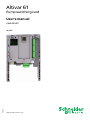
Altivar 61
Pump switching card
User’s manual
VW3 A3 502
1765272
10/2011
www.schneider-electric.com
Contents
Important information _________________________________________________________________________________________ 4
Before you begin_____________________________________________________________________________________________ 5
Documentation structure_______________________________________________________________________________________ 6
Description _________________________________________________________________________________________________ 7
Description of the terminals _________________________________________________________________________________ 8
Characteristics ___________________________________________________________________________________________ 9
Data backup battery ______________________________________________________________________________________ 10
Operating Principle __________________________________________________________________________________________
General ________________________________________________________________________________________________
Choosing a variable speed pump ____________________________________________________________________________
Choosing an auxiliary pump (fixed speed) _____________________________________________________________________
Operation using limited relative operating time__________________________________________________________________
Special cases ___________________________________________________________________________________________
Selecting the operating mode _______________________________________________________________________________
Controlling an auxiliary pump _______________________________________________________________________________
"Sleep" function/"Wake up" function __________________________________________________________________________
Compensation for loss of head (up to the version V1.1IE02) _______________________________________________________
Compensation for loss of head (up to the version V1.1IE02) (continued) _____________________________________________
Compensation for loss of head (from the version V1.2IE02) _______________________________________________________
Compensation for loss of head (from the version V1.2IE02) (continued) ______________________________________________
11
11
12
12
12
12
13
13
13
14
15
16
17
Menus - Parameter Setting____________________________________________________________________________________
Using the graphic display terminal or the setup software, in "connected to drive" mode __________________________________
[1.14 Multi pump] (En -) menu ______________________________________________________________________________
Parameters in the [1.14 Multi pump] (En -) menu________________________________________________________________
18
18
18
20
Architecture of the booster station ______________________________________________________________________________ 22
Connection diagrams ________________________________________________________________________________________ 23
Setup ____________________________________________________________________________________________________ 26
1765272 10/2011
3
Important information
PLEASE NOTE
Please read these instructions carefully and examine the device in order to familiarize yourself with it before installation, operation or
maintenance. The specific messages which follow can appear in the documentation or on the device. They warn you of potential dangers
or draw your attention to information which can clarify or simplify a procedure.
The presence of this symbol on a danger or warning label indicates that there is a risk of electrocution, which can cause
bodily injury if the instructions are not followed.
This is the symbol for a safety warning. It warns you of a potential danger of bodily injury. Follow all the safety instructions
accompanying this symbol to avoid any situation that can result in injury or death.
DANGER
DANGER indicates a dangerous situation resulting in death, serious injury or equipment damage.
WARNING
WARNING indicates a situation involving risks that can cause death, serious injury or equipment damage.
CAUTION
CAUTION indicates a potentially dangerous situation that can result in bodily injury or equipment damage.
IMPORTANT NOTE
The maintenance of electrical equipment must only performed by qualified personnel. Schneider Electric can in no way be held responsible
for the consequences of using this documentation. This document is not intended to be used as a guide by persons who have received no
training.
© 2011 Schneider Electric. All rights reserved.
4
1765272 10/2011
Before you begin
Read and understand these instructions before performing any procedure on this drive.
DANGER
RISK OF DANGEROUS VOLTAGE
• Read and understand this manual in full before installing or operating the variable speed drive. Installation, adjustment, repair, and
maintenance must be performed by qualified personnel.
• The user is responsible for compliance with all international and national electrical standards in force concerning protective grounding
of all equipment.
• Many parts of this variable speed drive, including the printed circuit boards, operate at the line voltage. DO NOT TOUCH.
Use only electrically insulated tools.
• DO NOT touch unshielded components or terminal strip screw connections with voltage present.
• DO NOT short across terminals PA and PC or across the DC bus capacitors.
• Install and close all the covers before applying power or starting and stopping the drive.
• Before servicing the variable speed drive
- Disconnect all power.
- Place a "DO NOT TURN ON" label on the variable speed drive disconnect.
- Lock the disconnect in the open position.
• Disconnect all power including external control power that may be present before servicing the drive. Wait for the charging LED to go
off. WAIT 15 MINUTES for the DC bus capacitors to discharge. Then follow the procedure for measuring the DC bus voltage given in
the Installation Manual. The drive LEDs are not accurate indicators of the absence of DC bus voltage.
Failure to follow these instructions will result in death, serious injury or equipment damage.
CAUTION
DAMAGED EQUIPMENT
Do not install or operate any drive that appears damaged.
Failure to follow this instruction can result in bodily injury and/or equipment damage.
1765272 10/2011
5
Documentation structure
Installation Manual
This manual describes:
• How to assemble the drive
• How to connect the drive
Programming manual
This manual describes:
• The functions
• The parameters
• Use of the drive terminal (integrated display terminal and graphic display terminal).
Communication Parameters Manual
This manual describes:
• The drive parameters with specific information (addresses, formats, etc.) for use via a bus or communication network
• The operating modes specific to communication (state chart)
• The interaction between communication and local control
Communication bus and network manuals (Modbus®, CANopen®, Ethernet™, Profibus®,
INTERBUS, DeviceNet™, etc.)
These manuals describe:
• Connection to the bus or network
• Configuration of the parameters specific to communication via the integrated display terminal or the graphic display terminal
• Diagnostics
• Software setup
• The protocol communication services
Altivar 38 compatibility manual
This manual describes the differences between the Altivar 61 and the Altivar 38.
It explains how to replace an Altivar 38, including how to replace drives communicating on a bus or network.
6
1765272 10/2011
Description
1 RJ45 connector (not used)
6
5
2 9-way male SUB-D connector for connection to the CANopen bus (not used)
4
3 Connector with removable screw terminals, 6 contacts at intervals of 3.81 for the
24 V c power supply and 4 logic inputs.
4 3 connectors with removable screw terminals, 6 contacts at intervals of 3.81 for 6 logic inputs,
6 logic outputs, 2 analog inputs, 2 analog outputs and 2 commons. Some inputs and outputs are
not used, as detailed on the next page.
1
2
3
5 5 LEDs, comprising:
• 1 to indicate the presence of the 24 V c power supply
• 1 to indicate a program execution fault
• 2 to indicate the CANopen bus communication status
• 1 controlled by the application program.
6 Block of 4 configuration switches (not used)
1765272 10/2011
7
Hardware setup
Description of the terminals
AO52
COM
AO51
AI52
COM
AI51
LO56
LO55
LO54
LO53
LO52
LO51
24V
COM
LI51
LI52
LI53
LI54
LI60
LI59
LI58
LI57
LI56
LI55
Terminals
Function
24V
Power supply for the pump switching card, logic outputs and analog outputs.
If allowed by the power consumption table (for example if outputs are not being used), the pump switching card can be
powered by the 24 V c power supply in the drive.
If you are using an external power supply:
• The pump switching card must be turned on before the drive is turned on, or at the same time as the drive is
turned on.
If this order is not followed, the drive will lock in a card fault (ILF). This fault cannot be reset, and the only way to
acknowledge it is to turn off the drive.
• Catalog number for a Schneider-Electric power supply (24 V c, 2A): ABL7 RE 24 02.
COM
(3 terminals)
Common ground and electrical 0V of the pump switching card power supply, logic inputs, (LIpp), outputs (LOpp), analog
inputs (AIpp) and analog outputs (AOpp).
This ground and electrical 0V are common with the drive ground and electrical 0V. There is therefore no point in
connecting this terminal to the 0V terminal on the drive control terminals.
LI51 to LI60
24 V c logic inputs
LI56 to LI60 = Not used
LO51 to LO56
24 V c logic outputs
LO56 = Not used
AI51 and AI52
0 ... 20mA analog inputs
Not used
AO51 and AO52 0 ... 20mA analog outputs
Not used
8
1765272 10/2011
Hardware setup
Characteristics
Electrical characteristics
Power supply
Voltage
V
24 c (min. 19, max. 30)
Current
consumption
Maximum
A
2
No-load
mA
80
Using logic output
mA
200 maximum (1)
Logic inputs
LI51…LI60
Impedance 4.4 kΩ
Maximum voltage: 30 V c
Switching thresholds:
State 0 if y 5 V or logic input not wired
State 1 if u 11 V
Common point for all the card I/O (2)
Logic outputs
LO51…LO56
Six 24 V c logic outputs, positive logic open collector type (source),
compatible with level 1 PLC, standard IEC 65A-68
Maximum switching voltage: 30 V
Maximum current: 200 mA
Common point for all the card I/O (2)
I/O connection
Type of contact
Lithium battery
Screw, at intervals of 3.81 mm2
Maximum capacity
mm
Tightening torque
Nm
Life
2
1.5 (AWG 16)
0.25
8 years
(1) If the power consumption table does not exceed 200 mA, this card can be powered by the drive. Otherwise, an external 24 V c power supply must be used.
(2) This common point is also the drive 0 V (COM).
1765272 10/2011
9
Hardware setup
Data backup battery
The pump switching card has a non-volatile RAM (NVRAM) which is needed to store variables. A lithium battery is mounted on this
non-volatile RAM to avoid this data being lost when the card is turned off.
When installing the pump switching card in the drive, make sure that this battery is
present. It takes the form of a rectangular block clipped onto the non-volatile RAM (see
schematic opposite).
The battery life is 8 years.
The battery has a realtime clock for timestamping faults.The precision of the clock is 3.76
seconds per day
The date and time on this clock are checked and set from a special sub-menu in the
[1.14 - Multi pump] (En -) customizable menu in the graphic display terminal.
The date and time need to be set on receipt of the pump switching card, or after replacing
its lithium battery.
The lithium battery must only be replaced when the drive and the pump switching card
are turned off.
Lithium
battery
During this operation, the data saved in the NVRAM (4 Kwords) is lost.
Important:
Spare part reference does not exist for the battery because of a problem of time storage. So, it is necessary to order it by your-self. The
reference of the baterry is TIMEKEEPER SNAPHAT M4T28-BR12SH1 (48mAh).
10
1765272 10/2011
Operating Principle
General
The main object is to control a complete pumping installation using a single ATV61 drive, providing:
- Constant pressure in the system whatever the flow rate
- A simple method for setting up and diagnosing the installation via the ATV61.
The system is operated using several fixed speed pumps (maximum of 4), and one variable speed pump, which is unable to provide the full
flow range required on its own. A PI regulator is used for pump control. The pressure sensor provides system feedback.
To avoid systematic wear of the same pumps, a function is provided that allows switching of the pumps according to their operating time.
The variable pump can also be included in this changeover procedure.
The variable speed pump (PV) is called a variable pump.
The fixed speed pumps are called auxiliary pumps.
Application example with 3 fixed pumps:
The auxiliary pumps are turned on and off according to the flow rate required by the installation. The variable pump is controlled so as to
ensure continuity in the flow rate variations.
Control of auxiliary pumps
Card
VW3A3502
Pressure
measurement
ATV 61
M
M1
PV
P1
M2
P2
M3
P3
Flow rate at
constant
pressure
PV: variable pump
P1, P2, P3: auxiliary pumps
Flow
rate
PV
P3
PV
PV
P1
PV
0
1765272 10/2011
1
2
P2
P2
P1
P1
3
4
Number of pumps
11
Operating Principle
The Altivar 61 controls the pumps via logic outputs LO51, LO52, LO53, etc., according to the operating mode that has been programmed.
The logic inputs indicate the state of the pumps to the Altivar 61:
- LI = 1, the pump is ready to operate
- LI = 0, the pump is faulty
Hour counters are used to determine the total operating time of each pump.
Choosing a variable speed pump
Single variable
In this mode, the same variable pump is always used. It is always controlled by the drive.
Multiple variable
In this mode, all the pumps can be variable (one at a time). The variable pump is chosen according to its operating time stored by the
Altivar 61: the pump with the shortest operating time is selected. The variable pump can only be changed over if all the auxiliary pumps are
off.
Choosing an auxiliary pump (fixed speed)
2 options:
- The auxiliary pumps are started in ascending order of the logic outputs (example: LO51, then LO52, then LO53, then LO54, then LO55).
The auxiliary pumps are stopped in descending order of the logic outputs (example: LO55, then LO54, then LO53, then LO52, then
LO51)
- Switching the auxiliary pumps
Starting up an auxiliary pump: the pump with the shortest operating time stored in the drive is selected.
Stopping an auxiliary pump: the pump with the longest operating time stored in the drive is selected.
Operation using limited relative operating time
A relative operating time differential between each pump can be programmed to ensure better distribution of operating times, thereby
limiting pump wear. If the total operating time differential between an operating auxiliary pump and one which is off exceeds the programmed
differential, the first pump is stopped and replaced by the second one.
The variable pump can only be replaced if all the auxiliary pumps are off, and if its operating frequency is below the programmed threshold
[V.pumpSwFr] (O18).
Special cases
If a pump is shown as "faulty" (LI=0), it is not taken into account by the Altivar 61 and the starting and stopping conditions apply only to the
other pumps.
12
1765272 10/2011
Operating Principle
Selecting the operating mode
The pump switching card provides 9 possible operating modes. These modes combine: the choice of variable pump, the choice of auxiliary
pump and limitation of relative operating time.
The mode is selected using the [Op. mode] (O01) parameter, ([1.14 Multi pump] (En -) menu).
Controlling an auxiliary pump
The PI regulator output (frequency reference of the variable pump) is used to control starting or stopping of an auxiliary pump with
hysteresis, as shown in the figure below:
Frequency of the
variable pump
Startup
of an auxiliary pump
HSP
Starting
frequency
Stop of an
auxiliary pump
Frequency
corresponding to the flow
rate of an auxiliary pump
Stopping
frequency
Flow rate of the installation
When the frequency exceeds the starting threshold ([FrqAuxPumpOn] (O12) parameter), a time delay ([Pump Delay On] (O03)
parameter) is started to avoid the effects of transient flow fluctuations. If after this time delay, the frequency remains higher than the starting
threshold, another pump is started. When the start command is sent, a time delay ([Acc Aux Pump] (O06) parameter) is started to allow
the pump to reach its nominal speed before starting another pump (avoids oscillation).
When the frequency is below the stopping threshold ([FrqAuxPumpOff] (O13) parameter), a time delay is started ([Pump Delay Off] (O04)
parameter) to avoid the effects of transient flow fluctuations. If after this time delay, the frequency remains below the stopping threshold, a
pump is stopped. When the stop command is sent, a time delay ([Dec Aux Pump] (O07) parameter) is started to allow the pump to reach
an effective stop before stopping another pump (avoids oscillation).
"Sleep" function/"Wake up" function
This function is used to stop the variable pump when the flow rate is zero (all the auxiliary pumps are off).
In this case, if the frequency of the variable pump is below the "sleep" threshold ([Sleep thresh] (O15) parameter), a time delay
([SleepFunctDel] (O05) parameter) is started. If, after this time delay [SleepFunctDel] (O05), the frequency remains below the [Sleep
thresh] (O15) threshold, the variable pump then stops. The installation is in "sleep" state.
To switch to "wake up" state, the pressure feedback must drop to below the "wake up" threshold ([WUp thresh] (O16) parameter). The
variable pump is then started.
PI feedback
[WUp thresh] (O16)
t
Motor
frequency
[Sleep thresh] (O15)
LSP
[SleepFunctDel] (O05)
t
Sleep threshold operating time
1765272 10/2011
13
Operating Principle
Compensation for loss of head (up to the version V1.1IE02)
An additional step [Pr adj coeff] (O14) is automatically added to the reference value each time an auxiliary pump is started. These reference
steps compensate for a loss of pressure (loss of head) in the pipework due to an increase in flow rate.
PID regulator reference
O14
Compensated
PID references
O14
O14
PID reference
Time
Run
Auxiliary pump 1
Stop
Run
Auxiliary pump 2
Stop
Run
Auxiliary pump 3
Stop
• Compensation for loss of head is active when the [Pr adj coeff] (O14) parameter is other than 0.
• The new PID regulator reference is generated using "PID preset reference 2" [Preset ref. PID 2] (rP2).
The [Preset ref. PID 2] (rP2) parameter is controlled by the pump switching card. It is therefore not possible to use the "PID
preset references" function with the "Compensation for loss of head" function.
Example of using the PID regulator with an internal reference:
• [Internal PID ref.] (rPI) = 400 (internal reference)
• [Min PID feedback] (PIF1) = 200
• [Max PID feedback] (PIF2) = 1000
• [Pr adj coeff] (O14) = 50
Each time an auxiliary pump is started the reference becomes:
- variable pump + 1 auxiliary pump: new reference = 450
- variable pump + 2 auxiliary pumps: new reference = 500
- variable pump + 3 auxiliary pumps: new reference = 550
14
1765272 10/2011
Operating Principle
Compensation for loss of head (up to the version V1.1IE02) (continued)
ATV61
AI2
User feedback (PIF) = (AI2)
AI1
User reference (Fr1) = (AI1)
PID
Variable Pump
speed setpoint
(rPC)
UVW
(rP2)
(Pr2) = (C415)
VW3 A3 502
LO51
Loss of head
compensation
LO52
Pumps
activation
LO53
LO54
LO55
1765272 10/2011
15
Operating Principle
Compensation for loss of head (from the version V1.2IE02)
An additional step [Pr adj coeff] (O14) is automatically substracted from the PID feedback each time an auxiliary pump is started. These
reference steps compensate for a loss of pressure (loss of head) in the pipework due to an increase in flow rate.
PID feedback
PID feedback
O14
Compensated
PID feedback
O14
O14
Time
Run
Auxiliary pump 1
Stop
Run
Auxiliary pump 2
Stop
Run
Auxiliary pump 3
Stop
• Compensation for loss of head is active when the [Pr adj coeff] (O14) parameter is other than 0.
• The new PID feedback is generated using "the virtual analog input" [Network AI] (AIU1).
The [Network AI] (AIU1) parameter is controlled by the pump switching card. It is therefore not possible to use the "virtual
analog input" with the "Compensation for loss of head" function.
16
1765272 10/2011
Operating Principle
Compensation for loss of head (from the version V1.2IE02) (continued)
ATV61
AI1
User reference (FR1) = (AI1)
AI2
User feedback
PID
Variable Pump
speed setpoint
UVW
(AIC1) = (APP)
(PIF) = (AIV1)
VW3 A3 502
LO51
Loss of head
compensation
LO52
Pumps
activation
LO53
LO54
LO55
1765272 10/2011
17
Menus - Parameter Setting
The various menus, the configuration, the settings and file transfers are accessed in the same way as with the standard drive using the
information given in the Programming Manuals, with the addition of the following special features:
Using the graphic display terminal or the setup software, in "connected to drive"
mode
If the VW3 A3502 card is present in the drive, some of the drive parameters which are necessary for the specific functions of the card are
automatically preconfigured. It also brings up a new [1.14 Multi pump] (En -) menu with new specific parameters to be configured.
If the display terminal or setup software is used, presence of the card is displayed in the IDENTIFICATION menu.
The following parameters are automatically configured by the card and cannot be modified:
• Assignment of logic inputs:
- LI1 = Start/stop the installation
- LI51 - LI52 - LI53 - LI54 - LI55
LO51 - LO52 - LO53 - LO54 - LO55
Parameter
Value up to the version V1.1IE02
Value from the version V1.2IE02
[Stop Key priority] (PSt)
[No] (nO)
[Non] (nO)
[Profile] (CHCF)
[Separate] (SEP)
[Separate] (SEP)
[Cmd switching] (CCS)
[ch1 active] (Cd1)
[ch1 active] (Cd1)
[Cmd channel 1] (Cd1)
[Prog. card] (APP)
[Prog. card] (APP)
[Cmd channel 2] (Cd2)
[Prog. card] (APP)
[Prog. card] (APP)
[Ref. 2 switching] (rFC)
[ch1 active] (Fr1)
[ch1 active] (Fr1)
[Ref.2 channel] (Fr2)
[No] (nO)
[No] (nO)
[Copy channel 1<>2] (COP)
[No] (nO)
[No] (nO)
[PID feedback ass.] (PIF)
[AI2] (AI2)
[Network AI] (AIU1)
[Ramp switch ass.] (rPS)
[C411] (C411)
[C411] (C411)
[2 preset PID ref.] (Pr2)
[C415] (C415)
-
[Low speed time out] (tLS)
[0] (0)
[0] (0)
[AI net. channel] (AICI)
-
[Prog. card] (APP)
All the parameters are described in the Programming Manual.
[1.14 Multi pump] (En -) menu
The parameters in the [1.14 Multi pump] (En -) menu are coded "OXX", XX varying from 01 to 20: see the list of parameters on the following
pages.
18
1765272 10/2011
Operation using the graphic display terminal
Setting the date and time
In the[1.14 Multi pump] (En -) menu, [DATE/TIME SETTINGS] submenu, the following can be set:
- Year
- Month
- Day
- Hours
- Minutes
NST
Term
0.00Hz
0.0A
DATE/TIME SETTINGS
22 : 42
Hour
Minutes
Month
Day
Year
11 / 03 / 2005
<<
>>
Quick
Note: The date and time are not refreshed on this settings screen. The current date and time [Date/Time] (CLO) can be displayed in the
[1.2 MONITORING] (SUP-) menu.
Note: It is not possible to change either the date or time format:
• The date cannot be displayed in the "year/month/day" format.
• The time cannot be displayed in the "10:42 pm" format, only in the "22:42" format.
Note: It is not possible to configure changes between winter and summer time.
1765272 10/2011
19
Menus - Parameter Setting
Parameters in the [1.14 Multi pump] (En -) menu
Code
Name
O01
[Op. mode]
O02
[No. of pumps]
Function
Description
Unit
Range
Selecting the operating mode
0: Pumps off
1: Single variable
2: Multiple variable
3: Single variable with changeover of auxiliary
pumps
4: Multiple variable with changeover of auxiliary
pumps
5: Single variable with limited relative operating time
6: Multiple variable with limited relative operating
time
7: Single variable with changeover of auxiliary
pumps and limited relative operating time
8: Multiple variable with changeover of auxiliary
pumps and limited relative operating time
0 to 8
Total number of pumps connected Includes the auxiliary pumps and the variable pump.
0 to 5
O03
[Pump Delay On] Time delay before starting an
auxiliary pump
This time is necessary to avoid the effects of
transient pressure fluctuation and thus prevent
oscillation (starting/stopping of the pump)
s
0 to 300
O04
[Pump Delay Off] Time delay before the request to
stop an auxiliary pump
This time is necessary to avoid the effects of
transient pressure fluctuation and thus prevent
oscillation (stopping/starting of the pump)
s
0 to 300
O05
[SleepFunctDel]
"Sleep" function time delay
If the frequency is below the "sleep" threshold after
this time, the "sleep" function is activated.
s
0 to 3000
O06
[Acc Aux Pump]
Time delay for reaching the
nominal speed of an auxiliary
pump
Allows the auxiliary pump to reach its nominal speed
before starting another pump (avoids oscillation)
s
0 to 300
O07
[Dec Aux Pump]
Time delay for stopping an
auxiliary pump
Allows the auxiliary pump to reach its zero flow rate
before stopping another pump (avoids oscillation)
s
0 to 300
O08
[Lim Rel Time]
Limited relative operating time
If the total operating time of a running auxiliary pump h
and a stopped pump differs by more than the time
set in O08, the first pump is stopped and replaced by
the second.
The unit can be changed from hours to minutes via
the O17 parameter (see next page), in order to
control operation.
0 to 3000
O09
[ResetOpTime]
Resets the operating counter of a
pump
Select the pump number using this parameter.
Press ENT. The operating time of the pump is reset
and the parameter automatically returns to 0. Use
when replacing a pump.
0 to 5
O10
[Pump no.]
Number of the pump with
operating time displayed in O11
If O10 = 0, parameter o11 indicates the value of the
pressure feedback.
0 to 5
O11
[Op. time]
Display of the operating time of
the pump selected by O10
If O10 = 0, this parameter indicates the value of the
pressure feedback (1).
h
0 to
65535
(1) The unit is determined by the [Min PID feedback] (PIF1) and [Max PID feedback] (PIF2) parameters, which are used to calibrate the
PID feedback (sensor range). See example on page 14.
20
1765272 10/2011
Menus - Parameter Setting
Code
Function
Description
Unit
Range
O12
Name
[FrqAuxPumpOn]
Starting frequency of a new
auxiliary pump
Above this frequency and after the time delay for
starting a pump (O03), another auxiliary pump
starts.
Hz
O13 to
[High
Speed]
(HSP)
O13
[FrqAuxPumpOff]
Stopping frequency of an
auxiliary pump
Below this frequency and after the time delay for
stopping an auxiliary pump (O04), the pump is
stopped.
Hz
[Low
speed]
(LSP) to
O12
O14
[Pr adj coeff]
Pressure adjustment coefficient
Coefficient used to adjust the pressure reference or
feedback to compensate for loss of head when the
hydraulic circuit is long (2).
(1)
0 to
32767
O15
[Sleep thresh]
"Sleep" threshold
This threshold activates the "sleep" time delay when
the frequency is below that set by the parameter.
Hz
0 to
[High
speed]
(HSP)
O16
[WUp thresh]
"Wake-up" threshold
Activates the variable pump and pressure regulation
when the installation has been in "sleep" state.
(1)
0 to 9999
O17
[Time base]
Modification of the time base of
O08
If O17 = 150, time O08 changes from hours to
minutes, enabling quick checking of the changeover
of the pumps during the debug or demonstration
phase.
O18
[V.pumpSwFr]
Frequency below which
changeover of variable pumps
is permitted
Determines the frequency below which changeover
of the variable pump is possible if the relative
operating time differential is reached.
If O18 = 0.0Hz, the changeover can only be
performed if the installation is in "sleep" state.
0 to 150
Hz
0 to
[High
speed]
(HSP)
(1) The unit is determined by the [Min PID feedback] (PIF1) and [Max PID feedback] (PIF2) parameters, which are used to calibrate the
PID feedback (sensor range). See example on page 14.
(2) This coefficient allows to adjust the pressure reference up to the version V1.1IE02 and the PID feedback from the version V1.2IE02.
The parametrization of the pump switching card with PC-Software is possible only in connected mode.
1765272 10/2011
21
Architecture of the booster station
Single variable mode with 5 pumps: 1 variable speed pump and 4 fixed speed pumps (auxiliary pumps)
4 fixed speed auxiliary pumps
Variable pump
ATV61
Pressure sensor
22
1765272 10/2011
Connection diagrams
Example of single variable diagram with 5 pumps
3-phase
supply
Q1
L1-L2-L3
Altivar 61+VW3A3502
PI feedback
AI2
COM
PI reference
AI1+
LO51
LO52
LO53
LO54
LO55
+10
Start/stop
CP5
LI1
Q1
Q2
Q3
Pump status
Q4
Q5
LI51
LI52
LI53
CP1
0V
LI55
24 V
Q2
KM5
KM4
KM3
KM2
M3
External 24 V c
power supply
24 V
P24
LI54
Q3
M4
CP2
Pump control
Q4
M5
CP3
COM
Q5
Pumps
CP4
U-V-W
KM1
M2
M1
Each pump is controlled by a logic output.
-
Pump 1 control via logic output LO51
Pump 2 control via logic output LO52
Pump 3 control via logic output LO53
Pump 4 control via logic output LO54
Pump 5 control via logic output LO55
The state of each pump must be sent back to the pump switching card via a logic input: 1 = the pump is ready to operate, 0 = the pump is
faulty.
-
State of pump 1 on logic input LI51
State of pump 2 on logic input LI52
State of pump 3 on logic input LI53
State of pump 4 on logic input LI54
State of pump 5 on logic input LI55
Example of single variable diagram with 5 pumps (continued)
CP1
KM1
Pump 1
CP2
KM2
Pump 2
For pumps 3 to 5, same diagrams, incrementing the indices (KMx, CPx).
1765272 10/2011
23
Connection diagrams
Example of multiple variable diagram with 5 pumps
3-phase
supply
Q
L1-L2-L3
Altivar 61+VW3A3502
PI feedback
AI2
COM
PI reference
AI1+
LO51
LO52
LO53
LO54
LO55
+10
Start/stop
Pump status
LI51
LI52
LI53
Q3
Q4
Q4
KM5
Pumps
KD5
M5
KD4
M4
CP2
CP1
0V
U-V-W
Q2
KD3
Q1
KM2
M3
External 24 V c
power supply
24 V
P24
LI55 24 V
KM3
CP3
Pump control
Q3
KM4
CP4
COM
LI54
Q5
Q5
CP5
LI1
Q1
Q2
KD2
KM1
M2
KD1
M1
Each pump is controlled by a logic output.
-
Pump 1 control via logic output LO51
Pump 2 control via logic output LO52
Pump 3 control via logic output LO53
Pump 4 control via logic output LO54
Pump 5 control via logic output LO55
The state of each pump must be sent back to the pump switching card via a logic input: 1 = the pump is ready to operate, 0 = the pump is
faulty.
-
State of pump 1 on logic input LI51
State of pump 2 on logic input LI52
State of pump 3 on logic input LI53
State of pump 4 on logic input LI54
State of pump 5 on logic input LI55
Example of multiple variable diagram with 5 pumps (continued)
CP1
KD5
KD5
CP2
KD4
KD3
KD2
KD1
KD4
KD5
KD3
KD4
KD2
KD1
KD5
KD4
KD3
KD3
KM1
KD1
KD1
Pump 1
KM1
KM2
KD2
KD2
KM2
Pump 2
For pumps 3 to 5, same diagrams, incrementing the indices (KDx, KMx, CPx).
24
1765272 10/2011
Connection diagrams
Example of multiple variable diagram with 5 pumps, with "manual/automatic" switching
3-phase
supply
Q
L1-L2-L3
Altivar 61+VW3A3502
PI feedback
AI2
COM
PI reference
AI1+
LO51
LO52
LO53
LO54
LO55
+10
Start/stop
Pump status/
enable
LI51
LI52
LI53
KA3
KA4
Q4
KM5
Pumps
KD5
KM4
M5
KD4
M4
KD3
M3
CP2
CP1
0V
External 24 V c
power supply
24 V
P24
U-V-W
Q2
KM3
CP3
Pump control
LI55 24 V
Q3
CP4
COM
LI54
KA5
Q5
CP5
LI1
KA1
KA2
Q1
KM2
KD2
KM1
M2
KD1
M1
Each pump is controlled by a logic output.
-
Pump 1 control via logic output LO51
Pump 2 control via logic output LO52
Pump 3 control via logic output LO53
Pump 4 control via logic output LO54
Pump 5 control via logic output LO55
The state and enabling of each pump must be sent back to the pump switching card via a logic input: 1 = the pump is enabled and ready
to operate, 0 = the pump is faulty or disabled.
-
State/enabling of pump 1 on logic input LI51
State/enabling of pump 2 on logic input LI52
State/enabling of pump 3 on logic input LI53
State/enabling of pump 4 on logic input LI54
State/enabling of pump 5 on logic input LI55
Example of multiple variable diagram with 5 pumps, with "manual/automatic" switching (continued)
KD5
KD4
KD3
KD1
KD2
KD5
Pump 1
KD4
KD3
KD2
KM1
KM1
KD1
KD5
KD4
KD3
KM2
KA1
KD2
KD2
Pump 1
Q2
KD3
KD4
KD1
KD1
CP2
Manual
Stop
Automatic
KD5
Q1
KM2
Pump 2
Manual
Stop
Automatic
CP1
KA2
Pump 2
For pumps 3 to 5, same diagrams, incrementing the indices (Qx, KAx, KDx, KMx, CPx).
1765272 10/2011
25
Setup
WARNING
RISK OF IMPROPER DRIVE OPERATION
The parameters in the [1.14 Multi pump] (En -) menu must be only modified when the drive is locked, i.e. when logic input LI1 is at 0.
This procedure must also be carried out in the following cases:
- Transferring configuration files
- Saving a configuration file
- Writing a parameter via the RS485 serial link
Failure to follow these instructions can result in death, serious injury or equipment damage.
1 - Enter via the [1.1 SIMPLY START] (SIM-) menu
RDY
App
+0.00Hz
MAIN MENU
1 DRIVE MENU
2 ACCESS LEVEL
3 OPEN / SAVE AS
4 PASSWORD
5 LANGUAGE
Code
REM
RDY
ENT
T/K
App
+0.00Hz REM
1 DRIVE MENU
1.1 SIMPLY START
1.2 MONITORING
1.3 SETTINGS
1.4 MOTOR CONTROL
1.5 INPUTS / OUTPUTS CFG
Code
<<
>>
T/K
• Leave the pumping/ventilation macro configuration (factory setting).
• Enter data from the motor rating plate: [Standard mot. freq] (bFr) - [Rated motor power] (nPr) - [Rated motor volt.] (UnS) [Rated mot. current] (nCr) - [Rated motor freq.] (FrS) - [Rated motor speed] (nSP) parameters.
• Perform an auto tune operation: [Auto tuning] (tUn) parameter. In order to perform the auto tuning operation, the [Op. mode] (O01)
parameter in the [1.14 Multi pump] (En -) menu must be 0, and a check must be carried out to ensure continuity of wiring between the
drive and the motor (if there is an output contactor it must be closed).
2 - Configure the pressure feedback (must be input AI2)
AI2 is automatically assigned by the "pump switching card".
[1.5 INPUTS / OUTPUTS CFG] (I-O-) menu
RDY
RDY
App
+0.00Hz
MAIN MENU
1 DRIVE MENU
2 ACCESS LEVEL
3 OPEN / SAVE AS
4 PASSWORD
5 LANGUAGE
Code
REM
ENT
App
+0.00Hz REM
1 DRIVE MENU
1.1 SIMPLY START
1.2 MONITORING
1.3 SETTINGS
1.4 MOTOR CONTROL
1.5 INPUTS / OUTPUTS CFG
Code
<<
>>
T/K
T/K
ENT
RUN
App
+0.00Hz REM
1.5 INPUTS / OUTPUTS CFG
AI2 CONFIGURATION
Code
<<
>>
T/K
Configure AI2 according to the pressure sensor being used (Example: 4 - 20 mA)
3 - Configure the PID regulator reference
The macro configuration Pumps / Fans assigns automatically the PID reference to AI1.
The factory configuration of AI1 is 0 - 10V.
The PID reference can be given by an internal reference:
• In the [1.7 APPLICATION FUNCT.] (FUn-) menu select the [PID REGULATOR] (PId-) function and the [Act. internal PID ref.] (PII) =
[Yes] (YES) parameter.
• The PID reference is then given by the [Internal PID ref.] (rPI) parameter.
26
1765272 10/2011
Setup
4 - Check the wiring of the pumps
[1.2 MONITORING] (SUP-) menu
RUN
App
+0.00Hz
1.2 MONITORING
I/O MAP
Controller Inside I/O MAP
COMMUNICATION
MAP
Alarm groups
:
HMI Frequency ref. :
Code
<<
>>
REM
ENT
Pump switching card I/O
T/K
The presence of the pumps can be checked via the state of the logic inputs on the pump switching card.
LI51 LI52 LI53 LI54 LI55
Pump switching card I/O
RUN
App
+50.00Hz REM
PROG. CARD I/O MAP
C. INSIDE CARD LI MAP
Controller inside AI MAP
C. INSIDE CARD LO MAP
Controller inside AO MAP
Code
State 0
RUN
State 1
1
0
Move from one screen to another
(from [C. INSIDE CARD LI MAP] to [Controller inside AO MAP])
by turning the navigation button
T/K
App
+50.00Hz
PROG CARD LI MAP
LI51 LI52 LI53 LI54 LI55
REM
LI56 LI57 LI58
LI59 LI60
1
0
<<
>>
T/K
The "pump feedback" logic inputs are used to ascertain the state of the pumps.
In the above diagram Pumps No. 1, No. 2, and No. 3 are present.
5 - Check the direction of rotation of the variable pump
The direction of rotation of the variable pump can be checked by switching to "control via graphic display terminal" mode:
Press the T/K key (F4 = default T/K assignment).
Set a low speed reference and give a run command in order to check the direction of rotation of the variable pump.
All of the wiring must be checked in order to ensure that the direction of rotation of the auxiliary pumps is identical.
6 - Check the pressure sensor: stay in "control via graphic display terminal" mode
[1.2 MONITORING] (SUP-) menu
[I/O MAP]
RUN
App
+50.00Hz
I/O MAP
LOGIC INPUT MAP
ANALOG INPUTS IMAGE
LOGIC OUTPUT MAP
ANALOG OUTPUTS IMAGE
FREQ. SIGNAL IMAGE
Code
REM
RUN
ENT
AI1
AI2
App
+50.00Hz REM
ANALOG INPUTS IMAGE
:
9.87 V
:
2.35 mA
T/K
Code
1765272 10/2011
Rotate the pump in order to check that
the pressure feedback varies according
to the motor speed.
<<
>>
T/K
27
Setup
7 - Determine the cavitation threshold (See the characteristics of the pump)
If the cavitation threshold is not known, it can be determined in the following way:
- In "control via graphic display terminal" mode, set the speed reference to the nominal speed of the variable pump. The speed reference
must then be gradually lowered (carry out tests at different initial flow rates). The flow rate decreases gradually then abruptly reaches
the cavitation point (the speed of the pump no longer has any effect on the flow rate).
- In regulation mode, run the variable pump then gradually close the shutoff valve. The flow rate decreases, the pressure tends to
increase, but the pressure regulation gradually reduces the speed of the pump to keep the pressure at the reference value. Read the
frequency value when the flow rate approaches zero flow rate (before cavitation)
Adjust [Low speed] (LSP) to 1 or 2 Hz above the point at which the flow rate drops.
The default value can be around 30Hz for a standard centrifugal pump.
8 - Set the parameters of the "pump switching" application
Check first that the wiring diagram corresponds to the selected mode.
[1.14 Multi pump] (En -) menu
Set: the values in parentheses are given for information only: they depend on the characteristics of the pumps and the hydraulic system.
[Op. mode] (O01)
Selection of the operating mode
[No. of pumps] (O02)
Total number of pumps connected
[Pump Delay On] (O03)
Time delay before starting an auxiliary pump (3 to 5 s)
[Pump Delay Off] (O04)
Time delay before the request to stop an auxiliary pump (3 to 5 s)
[SleepFunctDel] (O05)
"Sleep" function time delay (30 s)
[Acc Aux Pump] (O06)
Time delay for reaching the nominal speed of an auxiliary pump (1 to 2 s)
[Dec Aux Pump] (O07)
Time delay for stopping an auxiliary pump (1 to 2 s)
[Lim Rel Time] (O08)
Limited relative operating time
[FrqAuxPumpOn] (O12)
Starting frequency of a new auxiliary pump: [High speed] (HSP) - 2Hz
[FrqAuxPumpOff] (O13)
Stopping frequency of an auxiliary pump: [High speed] (HSP) - 12 Hz
[Pr adj coeff] (O14)
Pressure adjustment coefficient
[Sleep thresh] (O15)
"Sleep" threshold: 3 to 4 Hz above [Low speed] (LSP)
[WUp thresh] (O16)
"Wake-up" threshold: a few % below the PID reference
[Time base] (O17)
Modifying the time base of [Lim Rel Time] (O08), switches from a time base of hours to minutes, enabling
quick checking of the changeover of the pumps during the debug or demonstration phase.
[V.pumpSwFr] (O18)
Frequency below which changeover of variable pumps is permitted.
28
1765272 10/2011
Setup
9 - Set the PI regulator
[1.7 APPLICATION FUNCT.] (FUn-) menu, [PID REGULATOR] (PId-)
RDY
RDY
App
+0.00Hz
MAIN MENU
1 DRIVE MENU
2 ACCESS LEVEL
3 OPEN / SAVE AS
4 PASSWORD
5 LANGUAGE
Code
6 MONITORING CONFIG.
7 DISPLAY CONFIG.
REM
ENT
T/K
App
+0.00Hz REM
1 DRIVE MENU
1.1 SIMPLY START
1.2 MONITORING
1.3 SETTINGS
1.4 MOTOR CONTROL
1.5 INPUTS / OUTPUTS CFG
Code
<<
>>
T/K
1.6 COMMAND
1.7 APPLICATION FUNCT.
1.8 FAULT MANAGEMENT
1.9 COMMUNICATION
1.10 DIAGNOSTICS
1.11 IDENTIFICATION
1.12 FACTORY SETTINGS
1.13 USER MENU
1.14 PROGRAMMABLE CARD
RDY
ENT
App
+0.00Hz REM
1.7 APPLICATION FUNCT.
PID REGULATOR
PID PRESET REFERENCES
SLEEPING / WAKE UP
TORQUE LIMITATION
2nd CURRENT LIMIT.
Code
<<
>>
T/K
Example with a 0 - 10 bar sensor:
[Min PID feedback] (PIF1) = 0
[Max PID feedback] (PIF2) = 10,000 in order to have the best possible resolution
The maximum reference value for the process is 5 bar.
[Min PID reference] (PIP1) = 0
[Max PID reference] (PIP2) = 5,000
It can be adjusted from 0 to 5,000
Example for a 4 bar reference:
The reference is given by [Internal PID ref.] (rPI). To have a 4 bar reference, rPI must be set to 4000.
10 - Start the application
The PID regulator gains remain at their factory settings, and the application can be started. The PID starts smoothly with the
[Acceleration 2] (AC2) ramp: 5 seconds default setting.
The process can now be debugged:
- If the process is not fast enough or if there is an error in steady state, increase the gain.
- Set the auxiliary pump activation and deactivation thresholds to avoid cascaded starts and stops when there are minor variations in
demand.
1765272 10/2011
29
Setup
11 - Customize the display
Create a graph display with the following parameters: [PID reference] (rPC) and [PID feedback] (rPF)
[6. MONITORING CONFIG.] menu
RDY
App
+0.00Hz
MAIN MENU
1 DRIVE MENU
2 ACCESS LEVEL
3 OPEN / SAVE AS
4 PASSWORD
5 LANGUAGE
Code
6 MONITORING CONFIG.
7 DISPLAY CONFIG.
REM
RDY
T/K
ENT
App
+0.00Hz REM
6 MONITORING CONFIG.
6.1 PARAM. BAR SELECT
6.2 MONITOR SCREEN TYPE
6.3 COM. MAP CONFIG.
Code
<<
>>
T/K
[6.2. MONITOR SCREEN TYPE]: Selection of parameters displayed in the centre of the screen and the display mode (digital values or bar
graph format).
Deselect the current parameters and select [PID reference] (rPC) and [PID feedback] (rPF)
Select digital values display
RUN
App
+35.00Hz
PID reference
REM
1250
PID feedback
1200
Code
30
<<
>>
T/K
1765272 10/2011
Setup
12 - Create a user menu with the parameters necessary for adjusting the application
Switch to Advanced mode. Go to the [MAIN MENU] and select [2. ACCESS LEVEL] (LAC-) = [Advanced] (AdU).
RDY
RDY
App
+0.00Hz
MAIN MENU
1 DRIVE MENU
2 ACCESS LEVEL
3 OPEN / SAVE AS
4 PASSWORD
5 LANGUAGE
Code
REM
ENT
App
+0.00Hz
2 ACCESS LEVEL
REM
Basic
Standard
Advanced
Expert
Code
<<
>>
T/K
T/K
Go to the [7 DISPLAY CONFIG.] menu, then [7.2 USER MENU] to select the parameters required in the [1.13 USER MENU] (Usr).
RDY
App
+0.00Hz
MAIN MENU
1 DRIVE MENU
2 ACCESS LEVEL
3 OPEN / SAVE AS
4 PASSWORD
5 LANGUAGE
Code
6 MONITORING CONFIG.
7 DISPLAY CONFIG.
REM
RDY
T/K
ENT
App
+0.00Hz
7 DISPLAY CONFIG.
7.1 USER PARAMETERS
7.2 USER MENU
7.3 PARAMETER ACCESS
Code
<<
>>
REM
T/K
In the [1.7 APPLICATION FUNCT.] (FUn-) menu select V [PID REGULATOR] (PId-) V [PID prop. gain] (rPG) and [PID integral gain]
(rIG)
The following 2 parameters now appear in the [1.13 USER MENU] USr-):
- [PID prop. gain] (rPG)
- [PID integral gain] (rIG)
RDY
App
+0.00Hz
1.13 USER MENU
PID integral gain
:
PID prop. gain
:
Code
<<
1765272 10/2011
>>
REM
1.00
1.00
T/K
31
Setup
13 - Create a display in customer units for the [PID reference] (rPC) and [PID feedback] (rPF)
parameters
Example with a 0 - 10 bar sensor:
- [Min PID feedback] (PIF1) = 0
- [Max PID feedback] (PIF2) = 10,000 in order to have the best possible resolution in the operating range
Change the unit of the [PID reference] (rPC) and [PID feedback] (rPF) parameters and select mbar:
[MAIN MENU] V [7 DISPLAY CONFIG.] V [7.1 USER PARAMETERS] V select the parameters in [1.2 MONITORING] (SUP-): choose
[PID reference] (rPC) and [PID feedback] (rPF).
RDY
App
+0.00Hz
MAIN MENU
1 DRIVE MENU
2 ACCESS LEVEL
3 OPEN / SAVE AS
4 PASSWORD
5 LANGUAGE
Code
6 MONITORING CONFIG.
7 DISPLAY CONFIG.
REM
RDY
Rdy
App
+0.00Hz
7 DISPLAY CONFIG.
7.1 USER PARAMETERS
7.2 USER MENU
7.3 PARAMETER ACCESS
T/K
ENT
Code
PARAMETER SELECTION
1 DRIVE MENU
1.1 SIMPLY START
1.2 MONITORING
1.3 SETTINGS
1.4 MOTOR CONTROL
1.5 INPUTS / OUTPUTS CFG
T/K
List
ENT
<<
>>
REM
ENT
App
+0.00Hz REM
7.1 USER PARAMETERS
Return std name
:
No
PARAMETER SELECTION
CUSTOMIZED SELECTION
USER MENU NAME
DEVICE NAME
Code
<<
>>
T/K
T/K
PARAMETER SELECTION
1.2 MONITORING
Power on time
IGBT alarm counter
PID reference
PID feedback
PID error
T/K
List
RDY
ESC / ESC
App
+0.00Hz REM
7.1 USER PARAMETERS
Return std name
:
No
PARAMETER SELECTION
CUSTOMIZED SELECTION
USER MENU NAME
DEVICE NAME
Code
<<
>>
T/K
RDY
Term +0.00Hz REM
CUSTOMIZED SELECTION
PID reference
PID feedback
Rdy
RDY
Delete
Rdy
User name
Unit
Multiplier
Divisor
Offset
32
App
+0.00Hz
PID feedback
ENT
User name
Unit
Multiplier
Divisor
Offset
App
+0.00Hz
PID feedback
REM
ENT
Standard
:
1
:
1
: 0.00
T/K
ESC / ESC / ESC / ESC / ESC
mbar
:
1
:
1
: 0.00
T/K
+0.00Hz
Unit
REM
kWh
Hz
kHz
bar
mbar
ENT
T/K
RDY
REM
App
ENT
App
+0.00Hz
PID reference
Quick
REM
1250 mbar
PID feedback
1200 mbar
T/K
Quick
1765272 10/2011
Setup
14 - Save the configuration
The configuration that has been created can be saved in the graphic display terminal.
RDY
App
+0.00Hz
MAIN MENU
1 DRIVE MENU
2 ACCESS LEVEL
3 OPEN / SAVE AS
4 PASSWORD
5 LANGUAGE
Code
REM
RUN
ENT
App
+0.00Hz
3. OPEN / SAVE AS
RDY
REM
OPEN
SAVE AS
ENT
File 1
File 2
File 3
File 4
App
+0.00Hz REM
SAVE AS
Used
Free
Free
Free
T/K
Code
<<
>>
T/K
Code
T/K
In the [MAIN MENU] screen, select [SAVE AS]:
To download the current drive configuration to the graphic display terminal.
1765272 10/2011
33
34
1765272 10/2011
ATV61_carte_multi_pump_EN_1765272_04
1765272
10/2011