1
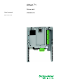
Altivar 71
Crane card
User’s manual
Retain for future use
VW3A3510
Contents
Important information _________________________________________________________________________________________ 4
Before you begin_____________________________________________________________________________________________ 5
Documentation structure_______________________________________________________________________________________ 6
Description _________________________________________________________________________________________________ 7
Description of the terminals _________________________________________________________________________________ 8
Characteristics ___________________________________________________________________________________________ 9
Data backup battery ______________________________________________________________________________________ 10
Operating principle __________________________________________________________________________________________
General ________________________________________________________________________________________________
Anti-sway operator assistance ______________________________________________________________________________
Cable length acquisition ___________________________________________________________________________________
12
12
13
14
Input/Output functions________________________________________________________________________________________
Assistance activation function_______________________________________________________________________________
End limit switch function ___________________________________________________________________________________
Slowing down switch function _______________________________________________________________________________
17
19
19
20
Menus - Parameter settings ___________________________________________________________________________________
CANopen configuration____________________________________________________________________________________
General configuration _____________________________________________________________________________________
Forced local mode _______________________________________________________________________________________
Fault reset______________________________________________________________________________________________
Fault management _______________________________________________________________________________________
Parameters in the [1.14 Crane] (SPL-) menu ___________________________________________________________________
21
21
22
24
24
24
25
Connection diagram _________________________________________________________________________________________ 30
Commissioning _____________________________________________________________________________________________
1 - Configure the motor parameters via the [1.4 MOTOR CONTROL] (drC-) menu______________________________________
2 - Wiring the crane card and the application part _______________________________________________________________
3 - Establish the CANopen connection ________________________________________________________________________
4 - Set the parameters of the "crane application" ________________________________________________________________
5 - Start up the system with the crane card and check the movements _______________________________________________
6 - Understanding the most important parameters for activating anti-sway assistance ___________________________________
7 - Slowing down switch and end limit switches _________________________________________________________________
31
31
31
32
35
35
36
43
3
Important information
PLEASE NOTE
Please read these instructions carefully and examine the device in order to familiarize yourself with it before installation, operation or
maintenance. The specific messages which follow can appear in the documentation or on the device. They warn you of potential dangers
or draw your attention to information which can clarify or simplify a procedure.
The presence of this symbol on a danger or warning label indicates that there is a risk of electrocution, which can cause
bodily injury if the instructions are not followed.
This is the symbol for a safety warning. It warns you of a potential danger of bodily injury. Follow all the safety instructions
accompanying this symbol to avoid any situation that can result in injury or death.
DANGER
DANGER indicates a dangerous situation resulting in death, serious injury or equipment damage.
WARNING
WARNING indicates a situation involving risks that can cause death, serious injury or equipment damage.
CAUTION
CAUTION indicates a potentially dangerous situation that can result in bodily injury or equipment damage.
IMPORTANT NOTE
The maintenance of electrical equipment must only performed by qualified personnel. Schneider Electric can in no way be held responsible
for the consequences of using this documentation. This document is not intended to be used as a guide by persons who have received no
training.
© 2008 Schneider Electric. All rights reserved.
4
Before you begin
Important: This option card is fully supported with the version V1.2 and above of the Altivar 71 firmware. This option card is only
supported with the version V1.2 and above of Altivar 31 firmware. Specific versions are not supported.
Read and understand these instructions before performing any procedure on this drive.
DANGER
RISK OF DANGEROUS VOLTAGE
• Read and understand this manual in full before installing or operating the variable speed drive. Installation, adjustment, repair, and
maintenance must be performed by qualified personnel.
• The user is responsible for compliance with all international and national electrical standards in force concerning protective grounding
of all equipment.
• Many parts of this variable speed drive, including the printed circuit boards, operate at the line voltage. DO NOT TOUCH.
Use only electrically insulated tools.
• DO NOT touch unshielded components or terminal strip screw connections with voltage present.
• DO NOT short across terminals PA and PC or across the DC bus capacitors.
• Install and close all the covers before applying power or starting and stopping the drive.
• Before servicing the variable speed drive:
- Disconnect all power.
- Place a "DO NOT TURN ON" label on the variable speed drive disconnect.
- Lock the disconnect in the open position.
• Disconnect all power including external control power that may be present before servicing the drive. Wait for the charging LED to go
off. WAIT 15 MINUTES for the DC bus capacitors to discharge. Then follow the procedure for measuring the DC bus voltage given in
the Installation Manual. The drive LEDs are not accurate indicators of the absence of DC bus voltage.
Failure to follow these instructions will result in death, serious injury or equipment damage.
CAUTION
DAMAGED EQUIPMENT
Do not install or operate any drive that appears damaged.
Failure to follow this instruction can result in bodily injury and/or equipment damage.
5
Documentation structure
Installation Manual
This manual describes:
• How to assemble the drive
• How to connect the drive
Programming Manual
This manual describes:
• The functions
• The parameters
• Use of the drive terminal (integrated display terminal and graphic display terminal)
Communication Parameters Manual
This manual describes:
• The drive parameters with specific information (addresses, formats, etc.) for use via a bus or communication network
• The operating modes specific to communication (state chart)
• The interaction between communication and local control
Communication bus and network manuals (Modbus, CANopen, Ethernet, Profibus, INTERBUS,
DeviceNet, etc.)
These manuals describe:
• Connection to the bus or network
• Configuration of the parameters specific to communication via the integrated display terminal or the graphic display terminal
• Diagnostics
• Software setup
• The protocol communication services
6
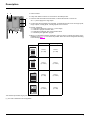
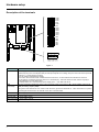
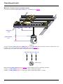
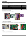
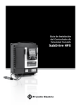
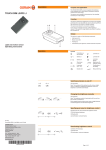
Description
1 RJ45 connector
6
5
2 9-way male SUB-D connector for connection to the CANopen bus
4
3 Connector with removable screw terminals, 6 contacts at intervals of 3.81 for the
24 V c power supply and 4 logic inputs
4 3 connectors with removable screw terminals, 6 contacts at intervals of 3.81 for 6 logic inputs,
6 logic outputs, 2 analog inputs, 2 analog outputs and 2 commons
1
2
3
5 5 LEDs, comprising:
• 1 to indicate the presence of the 24 V c power supply
• 1 to indicate a program execution fault
• 2 to indicate the CANopen bus communication status
• 1 controlled by the application program
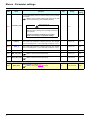
6 Block of 4 configuration switches. Switches 2 and 3 are used to configure the topology of the
installation (see page 21). Four cases are possible. Select the correct configuration according
to the following table:
Crane
Trolley
ATV31
(2 = ON)
ATV31
(3 = ON)
ATV71
(2 = OFF)
ATV71
(3 = OFF)
ATV31
(2 = ON)
ATV71
(3 = OFF)
ATV71
(2 = OFF)
ATV31
(3 = ON)
(1)
1
2
3
4
1
2
3
4
1
2
3
4
1
2
3
4
ON
ON
ON
ON
The switches represented in grey are not used to choose the configuration.
(1) The card is delivered in this configuration.
7
Hardware setup
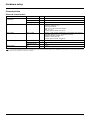
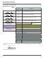
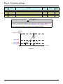
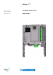
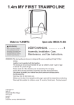
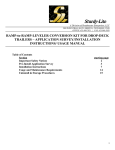
Description of the terminals
AO52
COM
AO51
AI52
COM
AI51
LO56
LO55
LO54
LO53
LO52
LO51
24V
COM
LI51
LI52
LI53
LI54
LI60
LI59
LI58
LI57
LI56
LI55
Figure 1
Terminals
Function
24V
Power supply for the crane card, logic outputs and analog outputs.
If allowed by the power consumption table (for example if outputs are not being used), the crane card can be powered
by the 24 V c power supply in the drive.
If you are using an external power supply:
• The crane card must be turned on before the drive is turned on, or at the same time as the drive is turned on.
If this order is not followed, the drive will lock in a card fault (ILF). This fault cannot be reset, and the only way to
acknowledge it is to turn off the drive.
• Catalog number for a Telemecanique power supply (24 V c, 2A): ABL7 RE 24 02.
COM
(3 terminals)
Common ground and electrical 0V of the crane card power supply, logic inputs, (LIpp), outputs (LOpp), analog inputs
(AIpp) and analog outputs (AOpp).
This ground and electrical 0V are common with the drive ground and electrical 0V. There is therefore no point in
connecting this terminal to the 0V terminal on the drive control terminals.
LI51 to LI60
24 V c logic inputs
LO51 to LO56
24 V c logic outputs
AI51 and AI52
0...20mA analog inputs
AO51 and AO52 0...20mA analog outputs
8
Hardware setup
Characteristics
Electrical characteristics
Power supply
Voltage
V
24 c (min. 19, max. 30)
Current
consumption
Maximum
A
2
No-load
mA
80
Using logic output
mA
200 maximum (1)
Logic inputs
LI51…LI60
Impedance 4.4 kΩ
Maximum voltage: 30 V c
Switching thresholds:
State 0 if y 5 V or logic input not wired
State 1 if u 11 V
Common point for all the card I/O (2)
Logic outputs
LO51…LO56
Six 24 V c logic outputs, positive logic open collector type (source),
compatible with level 1 PLC, standard IEC 65A-68
Maximum switching voltage: 30 V
Maximum current: 200 mA
Common point for all the card I/O (2)
I/O connection
Type of contact
Lithium battery
Screw, at intervals of 3.81 mm2
Maximum capacity
mm
Tightening torque
Nm
Life
2
1.5 (AWG 16)
0.25
8 years
(1) If the power consumption table does not exceed 200 mA, this card can be powered by the drive. Otherwise, an external 24 V c power supply must be used.
(2) This common point is also the drive 0 V (COM).
9
Hardware setup
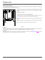
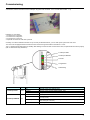
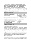
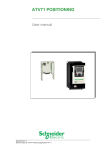
Data backup battery
The crane card has a non-volatile RAM (NVRAM) which is needed to store variables. A lithium battery is mounted on this non-volatile RAM
to avoid this data being lost when the card is turned off.
When installing the crane card in the drive, make sure that this battery is present. It takes
the form of a rectangular block clipped onto the non-volatile RAM (see schematic
opposite).
The battery life is 8 years.
The battery has a realtime clock for timestamping faults.
The date and time on this clock are checked and set from a special sub-menu in the
[1.14 - Crane] (SLE-) customizable menu in the graphic display terminal.
The date and time need to be set on receipt of the crane card, or after replacing its lithium
battery.
The lithium battery must only be replaced when the drive and the crane card are turned
off.
Lithium
battery
During this operation, the data saved in the NVRAM (4 Kwords) is lost.
Figure 2
Important 1:
There is no spare part catalog number for the battery because of the issue of storage life. Users are responsible for ordering their own
replacement battery. The battery product reference is TIMEKEEPER SNAPHAT M4T28-BR12SH1 (48mAh).
Important 2:
If the battery is changed, the crane card return automatically in factory setting (see parameter O32 [FACTORY_SET] page 28). The logic
output LO52 stays to 0 V to the next starting of the crane card without problem.
10
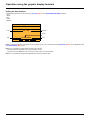
Operation using the graphic display terminal
Setting the date and time
The following information can be set in the [1.14 Crane] (SPL-) menu, [DATE/TIME SETTINGS] submenu:
- Year
- Month
- Day
- Hours
- Minutes
NST
Term
0.00Hz
0.0A
DATE/TIME SETTINGS
22 : 42
Hour
Minutes
Month
Day
Year
11 / 03 / 2005
<<
>>
Quick
Note: The date and time are not refreshed on this settings screen. The current date and time [Date/Time] (CLO) can be displayed in the
[1.2 MONITORING] (SUP-) menu.
Note: It is not possible to change either the date or time format:
• The date cannot be displayed in the "year/month/day" format.
• The time cannot be displayed in the "10:42 pm" format, only in the "22:42" format.
Note: It is not possible to configure changes between winter and summer time.
11
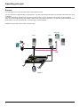
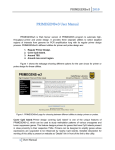
Operating principle
General
The main objective is to control load sway without using additional sensors.
The crane card can be integrated easily in a standard drive. The same electrical operator interface is used without the need for any wiring
modification.
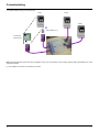
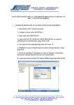
The card is integrated by automatic drive recognition and takes control in order to manage the entire system via CANopen fieldbus.
Safety zones are managed through limit switches (slowing down switch and end limit switch). The anti-sway operator assistance works
simultaneously on 2 axes (including trolley, crane and hoist for position feedback).
Application example with 3 drives (trolley, hoist and crane):
Crane card
Hoist
Crane
Trolley
CAN
Figure 3
12
Operating principle
Anti-sway operator assistance
Suspended loads are subject to sway during trolley (or crane) movement. Only experienced operators can efficiently bring a load to a
sway-free stop without the crane card. Use of the crane card offers significant time savings, since it means that no time is lost waiting for a
load to stop swaying or during difficult fine positioning operations.
SWAY assists the crane operator by modifying the speed command signal to the movement drive so that sway is continuously limited. When
the load is brought to the desired speed or to a halt, there is a little or no sway.
+
SWAY
Controller
Estimator
L
Safety control
Figure 4
Estimator
An adaptive model is used to estimate load sway based on:
- the drive’s internal signals
- the cable length
Controller
This is an adaptive continuous controller providing anti-sway correction to the operator command.
Safety control
- Safety zones for slowing down and stopping
- Activation and deactivation of the anti-sway assistance
Trolley
End limit switch
Slowing down switch
Right
Left
Forward
Crane
L_Cable
Reverse
[LOAD_LENGTH]
(O29)
Figure 5
The parameter [LOAD_LENGTH] (O29) (see page 27) must be used if the load is repetitive and if this information is available.
13
Operating principle
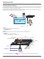
Cable length acquisition
There are three methods for measuring the load cable length:
• Via encoder
• Via input from 2 limit switches on the hoist
• Via input from a 3-position selector
The method is selected via parameter [ACQ_CBL_CONF] (O25) in the [1.14 Crane] (SPL-) menu (see page 27).
Method 1: Via encoder
This method is selected when [ACQ_CBL_CONF] (O25) = [encoder] (1) (see page 27).
Important : The choose of this method implies 2 points for the hoisting drive:
• It must be connected to CANopen in order to be able to read encoder value through the fieldbus
• It must be configured in closed loop current flux vertor control [FVC] (FUC) and the encoder test must have been done (see ATV71
programming manual).
LI58 =
up limit switch
LI58 =
up limit switch
Figure 6
Logic input LI58 is used for the up limit switch.
Step 1:
Logic output LO51 flashes until the up limit switch is reached.
Move the load to the up limit switch position (LI58 = 1). The value of the encoder position is set to 0 each time the up limit switch is activated.
Step 2:
Lower the load and enter the corresponding cable length in parameter [RES_ENC] (O38) in the [1.14 Crane] (SPL-) menu on the keypad
(see page 28).
Important: In order to ensure optimum accuracy, it is necessary to use the maximum possible cable length.
The encoder resolution is calculated by the card using the formula:
resolution = ([RES_ENC] (O38) * 10000 pulses) / number of pulses
Example:
[RES_ENC] (O38) = 20 meters
The read value for the encoder position is: number of pulses = 3087210
Encoder resolution = (20 * 10000) / 3087210 = 0.06478 m
This value is used by the software to determine the cable length during nominal operation.
Note: It is possible to recalibrate the cable length (for example, after changing the encoder or in the event of a wrong adjustment of
[RES_ENC] (O38)). In this case, it is necessary to switch the value of [ACQ_CBL_CONF] (O25) from [encoder] (1) to
[3 switches] (2), and then return to [encoder] (1). Then restart the procedure from Step 1.
14
Operating principle
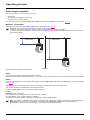
Method 2: Via input from 2 limit switches on the hoist
This method is selected when [ACQ_CBL_CONF] (O25) = [2 switches] (0) (see page 27).
[MIDD_POS]
(O27)
[HIGH_POS]
(O26)
LI58
LI59
[LOW_POS]
(O28)
[LOAD_LENGTH]
(O29)
Figure 7
LI58 and LI59 are symbolic in this figure. The usual way is to use a screw selector to activate LI58 and LI59.
The three parameters [HIGH_POS] (O26), [MIDD_POS] (O27) and [LOW_POS] (O28) correspond to the three working areas of the
installation. They can be configured in the [1.14 Crane] (SPL-) menu (see page 27).
During operation, the working area is selected automatically by switches LI58 and LI59 according to the following table:
Working area
[HIGH_POS] (O26)
[MIDD_POS] (O27)
[LOW_POS] (O28)
LI58
0
1
1
LI59
0
0
1
The load height can imply a shifting of the gravity center. To maintain the accuracy of the anti-sway function, the presence of the load must
be validated using LI60, in order to automatically add the [LOAD_LENGTH] (O29) (see page 27):
Description
Load present
Load not present
LI60
1
0
Total cable length
Result of cable length acquisition + [LOAD_LENGTH] (O29)
Result of cable length acquisition
15
Operating principle
Method 3: Via input from a 3-position selector
This method is selected when [ACQ_CBL_CONF] (O25) = [3 switches] (2) (see page 27).
[MIDD_POS]
(O27)
[HIGH_POS]
(O26)
[LOW_POS]
(O28)
[LOAD_LENGTH]
(O29)
Figure 8
The three parameters [HIGH_POS] (O26), [MIDD_POS] (O27) and [LOW_POS] (O28) correspond to the three working areas of the
installation. They can be configured in the [1.14 Crane] (SPL-) menu (see page 27).
During operation, the operator must select the working area using the 3-position selector.
[HIGH_POS]
[MIDD_POS] [LOW_POS]
LI58
LI59
LI60
1
2
3
3-position selector
Note: Parameter [LOAD_LENGTH] (O29) (see page 27) is always added to the result of cable length acquisition.
Example 1: If [LOAD_LENGTH] (O29) = 0 m, total length = result of cable length acquisition.
Example 2: If [LOAD_LENGTH] (O29) = 5 m, total length = result of cable length acquisition + 5 meters.
16
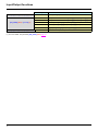
Input/Output functions
The following tables show the I/O assignments.
The functions of LI3, LI58, LI59 and LI60 depend on the cable length measurement method. This method is selected via parameter
[ACQ_CBL_CONF] (O25) (see page 27).
Crane card logic
inputs
T. switch left
Function
LI51
Assistance activation switch
LI52
Trolley end limit switch on right and left (1)
LI53
Trolley slowing down switch on right and left
LI54
Crane end limit switch on forward and reverse (1)
LI55
Crane slowing down switch on forward and reverse
LI58
Load height bit1
LI59
Load height bit2
LI60
Load present or not
LI58
Up limit switch (positive logic)
LI60
Load present or not
LI58
Load is in high position
LI59
Load is in middle position
LI60
Load is in low position
T. switch right
+ 24 V
LI52
T. slowing d. left
T. slowing d. right
+ 24 V
LI53
C. switch rev. C. switch fwd
+ 24 V
LI54
C. slowing d. rev
C. slowing d. fwd
+ 24 V
LI55
[ACQ_CBL_CONF] (O25) =
[2 switches] (0)
[ACQ_CBL_CONF] (O25) = [encoder] (1)
[ACQ_CBL_CONF] (O25) =
[3 switches] (2)
Crane logic output
Binary combination for the 3
choices
Function
LO51
Active assistance indicator
LO52
Error indicator (2)
Drive logic inputs
Function
LI1
Forward direction
LI2
Reverse direction
Drive logic inputs
Function
LI1
Right direction
LI2
Left direction
(1) If an anti-collision system is used, consider only one end limit switch. Insert the anti-collision switch in serie with the run command.
Example:
Anti-collision
FW
FW
+ 24 V
LI1
(2) Activated (LO52=24 V) in case of no error.
17
Input/Output functions
Drive inputs
[RQ_CONF] (O31) = [LI3] (0)
[RQ_CONF] (O31) = [LI3 4 5] (1)
[RQ_CONF] (O31) = [AI1] (2)
LI3
Low speed/High speed
LI1
Low speed in forward direction [LSPD_C] (O22) and [LSPD_T] (O24)
LI2
Low speed in reverse direction [LSPD_C] (O22) and [LSPD_T] (O24)
LI3
Preset speed 3 [SP3_C] (O39) and [SP3_T] (O41)
LI4
Preset speed 4 [SP4_C] (O40) and [SP4_T] (O42)
LI5
High speed [FSPD_C] (O21) and [FSPD_T] (O23)
AI1
Speed reference (0 - 10 V)
(1) For more details, see parameter [RQ_CONF] (O31) page 27.
18
Function (1)
Input/Output functions
Assistance activation function
The activation of anti-sway function has effect when the two axis are stopped. If one of the two axis is on movement when LI51 is active,
the function wil be effective only after a stop and a start of the movement.
This function is active when LI51 = 24 V.
Speed
Time
Figure 9
The anti-sway function is not active when LI51 = 0 V.
Speed
Time
Figure 10
End limit switch function
The trolley end limit switch on right and left function is active when LI52 = 0 V with movement. The crane end limit switch on forward and
reverse function is active when LI54 = 0 V with movement.
The drive stops with a quick stop in both cases (anti-sway function active or not) and the speed decreases automatically until 0 Hz (see
page 43 for additional information).
If a end limit switch is crossed, the reverse movement will restart only after a complete stop of the axis.
19
Input/Output functions
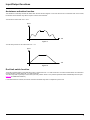
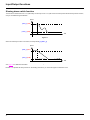
Slowing down switch function
This function is active when LI53 = 0 V (with trolley movement) or LI55 = 0 V (with crane movement). When the anti-sway function is active,
sway is controlled during deceleration:
Speed
[FSPD_C] (O21)
[LSPD_C] (O22)
Time
LI53 or LI55
Figure 11
When the anti-sway function is not active, the ramp follows [T_DEC1_x]:
Speed
[FSPD_C] (O21)
[LSPD_C] (O22)
Time
LI53 or LI55
Figure 12
See page 43 for additional information.
Remark : To optimize anti-sway function on the slowing-down area, you can be brought to increase this zone.
20
Menus - Parameter settings
The various menus, configuration, settings and file transfers are accessed in the same way as with the standard drive using the information
given in the Programming Manuals, with the addition of the following special features:
If the crane card is present in the drive a new [1.14 Crane] (SPL-) menu appears with new specific parameters to be configured.
If the display terminal is used, presence of the card is displayed in the IDENTIFICATION menu.
Bit 9 of the Extended Control Word parameter (CMI) is automatically preconfigured in order to have a higher resolution on the
[Frequency ref.] (LFr) and [Output frequency] (rFr) units. This parameter is written in the drive via the CANopen fieldbus.
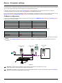
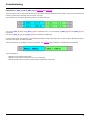
CANopen configuration
For ATV71, the following parameters must be configured by the user in the [1.9 - COMMUNICATION] (COM) menu ([CANopen] (CnO-)
submenu) and must not be modified:
Drive(s) affected
Parameter
Value
All (trolley, crane, ...)
[CANopen bit rate] (bdCO)
[500 kbps] (500) (1)
ATV71 Trolley
[CANopen address] (AdCO)
[2] (2) (2)
ATV71 Crane
[CANopen address] (AdCO)
[3] (3) (2)
ATV71 Hoist
[CANopen address] (AdCO)
[4] (4) (2)
For ATV31, the following parameters must be configured by the user in the (COM-) menu and must not be modified:
Drive(s) affected
Parameter
Value
All (trolley, crane, ...)
(bdCO)
(500) (1)
ATV31 Trolley
(AdCO)
(5) (2)
ATV31 Crane
(AdCO)
(6) (2)
(1) The value of CANopen bit rate (bdCO) parameter corresponds to the communication speed of all devices connected to the CANopen
fieldbus.
(2) The value of the [CANopen address] (AdCO) depends on the configuration of the installation, but remains fixed for each kind of
movement.
ATV71 Trolley
@2
ATV71 Crane
@3
Crane
card
ATV71 Hoist
@4
Figure 13
Important: The drives must be restarted in order to take the communication parameters into account.
These 2 parameters are described in the CANopen User’s Manual.
Important: It is mandatory to connect the ATV71 Hoist to the CANopen fieldbus only if the cable acquisition method is [encoder] (1).
The ATV71 Hoist must be equipped with an encoder card.
21
Menus - Parameter settings
General configuration
Depending on the application configuration selected using the switches (see page 7), it is necessary to configure ATV71 and/or ATV31
drives.
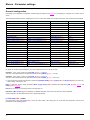
The following parameters must be configured on an ATV71 crane drive and/or ATV71 trolley drive by the user and must not be modified:
Menu
Submenu
Parameter
Value
[SIMPLY START] (SIM-)
-
[Macro configuration] (CFG)
[M. handling] (HdG) (1)
[COMMAND] (CtL-)
-
[Profile] (CHCF)
[Not separ.] (SIM)
[COMMAND] (CtL-)
-
[Ref.1 channel] (Fr1) (2)
[CANopen] (CAn)
[SETTINGS] (SEt-)
-
[Acceleration] (ACC)
[0.1] (0.1)
[SETTINGS] (SEt-)
-
[Deceleration] (dEC)
[0.1] (0.1)
[SETTINGS] (SEt-)
-
[Low speed] (LSP)
[0] (0)
[SETTINGS] (SEt-)
-
[Acceleration 2] (AC2)
[5] (5)
[SETTINGS] (SEt-)
-
[Deceleration 2] (dE2)
[5] (5)
[APPLICATION FUNCT.] (FUn-)
[BRAKE LOGIC CONTROL] (bLC-)
[Brake assignment] (bLC)
[R2] (r2)
[APPLICATION FUNCT.] (FUn-)
[BRAKE LOGIC CONTROL] (bLC-)
[Movement type] (bSt)
[Traveling] (HOr)
[APPLICATION FUNCT.] (FUn-)
[BRAKE LOGIC CONTROL] (bLC-)
[Brake Release time] (brt)
[0] (0)
[APPLICATION FUNCT.] (FUn-)
[BRAKE LOGIC CONTROL] (bLC-)
[Brake engage delay] (tbe)
[0] (0)
[APPLICATION FUNCT.] (FUn-)
[RAMP] (rPt-)
[Ramp switch ass.] (rPS)
[LI6] (LI6) (3)
[APPLICATION FUNCT.] (FUn-)
[PRESET SPEEDS] (PSS-)
[2 preset speeds] (PS2)
[No] (no)
[APPLICATION FUNCT.] (FUn-)
[PRESET SPEEDS] (PSS-)
[4 preset speeds] (PS4)
[No] (no)
[APPLICATION FUNCT.] (FUn-)
[PRESET SPEEDS] (PSS-)
[8 preset speeds] (PS8)
[No] (no)
[APPLICATION FUNCT.] (FUn-)
[PRESET SPEEDS] (PSS-)
[16 preset speeds] (PS16)
[No] (no)
[COMMUNICATION] (COM-)
[FORCED LOCAL] (LCF-)
[Forced local assign.] (FLO)
[LI6] (LI6) (3)
[COMMUNICATION] (COM-)
[FORCED LOCAL] (LCF-)
[Forced local Ref.] (FLOC)
[AI2] (AI2)
[INPUTS / OUTPUTS CFG] (I_O-) [AI2 CONFIGURATION] (AI2-)
[AI2 Interm. point Y] (AI2S)
[20%] (20)
[FAULT MANAGEMENT] (FLt-)
[FAULT RESET] (rSt-)
[Fault reset] (rSF)
[LI6] (LI6) (3)
[FAULT MANAGEMENT] (FLt-)
[COM. FAULT MANAGEMENT] (CLL-) [CANopen fault mgt] (COL)
[Freewheel] (YES)
(1) This parameter must be assigned first of all.
(2) When AI1 is used as speed reference, AI1 value is between 0 and 10 V (0 and 10 000).
Example 1 : If AI1 crane = 5000 (5 V) and [FSPD_C] (O21) = 1.000 m/s
Then, the crane speed reference is equal to 0.500 m/s (even if [VMAX_C] (O01) = 1.5 m/s).
Example 2 : If AI1 trolley = 1000 (1 V) and [FSPD_T] (O22) = 0.333 m/s
Then, the trolley speed reference is equal to 0.333 m/s (even if [VMAX_T] (O11) = 0.750 m/s)
(3) The access level must be set to Expert or Advanced ([ACCESS LEVEL] (LAC-)= [Expert] (EPr) or [Advanced] (Adu)) in order to be
able to assign 2 functions to LI6.
Note 1: If anti-sway mode is active, parameter [Brake engage delay] (tbE) is rewritten (see parameters [TBE_C] (O33) page 28 and
[TBE_T] (O34) page 28).
Note 2: Do not assign any summing function to analog input AI1.
Important: If [Max frequency] (tFr) is modified, it is updated and taken into account only when the drive is restarted.
All the parameters are described in the ATV71 Programming Manual.
[1.14 Crane] (SPL-) menu
The parameters in the [1.14 Crane] (SPL-) menu are coded "OXX", "XX" varying from 01 to the last crane parameter: see the list of
parameters on the following pages.
22
Menus - Parameter settings
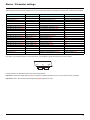
The following parameters must be configured on an ATV31 crane drive and/or ATV31 trolley drive by the user and must not be modified:
Menu
Control menu (CtL-)
Control menu (CtL-)
Control menu (CtL-)
Settings menu (SEt-)
Settings menu (SEt-)
Settings menu (SEt-)
Application function menu (FUn-)
Application function menu (FUn-)
Application function menu (FUn-)
Application function menu (FUn-)
Application function menu (FUn-)
Application function menu (FUn-)
Application function menu (FUn-)
Application function menu (FUn-)
Application function menu (FUn-)
Application function menu (FUn-)
Application function menu (FUn-)
Communication menu (COM-)
Communication menu (COM-)
Fault menu (FLt-)
Fault menu (FLt-)
Submenu
Brake control (bLC-)
Brake control (bLC-)
Brake control (bLC-)
Brake control (bLC-)
Ramps (rPC-)
Preset speeds (PSS-)
Preset speeds (PSS-)
Preset speeds (PSS-)
Preset speeds (PSS-)
-
Parameter
Function access level (LAC)
Mixed mode (CHCF)
Configuration reference (Fr1)
Acceleration ramp time (ACC)
Deceleration ramp time (dEC)
Low speed (LSP)
2nd acceleration ramp time (AC2)
2nd deceleration ramp time (dE2)
Brake control configuration (bLC)
Brake engage frequency threshold (bEn) (3)
Brake release time (brt) (3)
Brake engage time (bEt) (3)
Ramp switching (rPS)
2 preset speeds (PS2)
4 preset speeds (PS4)
8 preset speeds (PS8)
16 preset speeds (PS16)
Forced local mode (FLO) (4)
Forced local reference (FLOC) (4)
Reset of current fault (rSF)
CANopen fault management (COL)
Value
Access to advanced function (L3)
Combined (SIM)
Reference from CANopen (CAn)
(0.1)
(0.1)
(0)
(5)
(5)
(R2)
(0)
(0)
(0)
(LI6)
(nO)
(nO)
(nO)
(nO)
(LI6)
(AI2)
(LI6)
Freewheel stop (YES)
(4) These parameters only appear if the brake control configuration function (BLC) has been enabled.
(5) In order to get a speed reference in forced local mode, it is mandatory to apply a fixed reference as shown below:
+10 V
300 Ω
COM
AI2
2.2 kΩ
All the parameters are described in the ATV31 Programming Manual.
Important 1: If Maximum output frequency (tFr) is modified, it is updated and taken into account only when the drive is restarted.
Important 2: ATV31 drive cannot work with High speed (HSP) upper than 60.0 Hz.
23
Menus - Parameter settings
WARNING
UNINTENDED EQUIPMENT OPERATION
Do not change the value of parameter [CANopen fault mgt] (COL) = [Freewheel] (YES) for ATV71
and CANopen fault management (COL) = Freewheel stop (YES) for ATV31.
Failure to follow these instructions can result in death, serious injury or equipment damage.
Forced local mode
It is possible to switch from CANopen control to local control via logic input 6. As soon as forced local mode is released, CANopen takes
control of the system and manages the drives.
WARNING
UNINTENDED EQUIPMENT OPERATION
In forced local mode, no limit switch or slowing down switch is taken in account. The operator must
take great care to observe the real end limits of the bridge without the assistance of these switches.
Failure to follow these instructions can result in death, serious injury or equipment damage.
Fault reset
It is possible to reset faults locally if the cause has disappeared.
Fault management
WARNING
UNINTENDED EQUIPMENT OPERATION
The drive stop mode after a fault must be configured on [Freewheel] (YES) (factory setting - for more
details, see ATV71 programming manual).
Failure to follow these instructions can result in death, serious injury or equipment damage.
24
Menus - Parameter settings
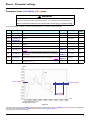
Parameters in the [1.14 Crane] (SPL-) menu
WARNING
RISK OF DYSFUNCTION OF THE APPLICATION
Check the consistency between the parameters of the crane card (there is no interdependence).
Failure to follow these instructions can result in death, serious injury or equipment damage.
In the following tables, the suffix _C relates to a crane parameter, _T relates to a trolley parameter.
Function
Unit
Range
Factory
setting
Code
Name
O01
[VMAX_C]
Maximum linear crane speed at [FMAX_C]
m/s
0.000 to 4.0000
1.0
O02
[FMAX_C]
Nominal crane drive frequency at [VMAX_C]
Hz
50 to 100
50
s
0.5 to 10.0
4.0
O03
[T_ACC1_C]
Crane accelerating time - manual mode. Used when anti-sway is
inactive
O04
RESERVED
-
-
-
-
O05
[T_DEC1_C]
Crane decelerating time - manual mode. Used when anti-sway is
inactive
s
0.5 to 10.0
3.5
O06
RESERVED
-
-
-
-
O07
[V_ACT_C]
Crane speed activation threshold for anti-sway. See figure 14
page 25
% of
[VMAX_C]
0.0 to 100.0
25.0
O08
[V_ASW_C]
Modification of crane sway behavior. Allows more or less rigid
correction of the ramps (anti-sway mode active). To be adjusted
case by case.
% of
[VMAX_C]
0.0 to 100.0
60.0
O09
[V_END_C]
Crane speed threshold for end movement. See figure 14 page 25
% of
[VMAX_C]
0.0 to 5.0
0.6
O10
[T_END_C]
Crane time at speed threshold for end movement.
See figure 14 page 25
ms
0 to 2000
800
Speed
Teta
v
[V_ACT_C] (O07)
[V_END_C] (O09)
[T_END_C] (O10)
Time
v: Trolley velocity with anti-sway
Teta: Sway angle in mdeg
Figure 14
If the crane speed is lower than [V_END_C] (O09) during a time greater than or equal to [T_END_C] (O10), then the drive is stopped with
a stop ramp. The anti-sway effect is restarted when the speed reaches [V_ACT_C] (O07).
The principle is the same for the Trolley.
25
Menus - Parameter settings
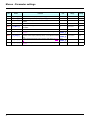
Name
O11
[VMAX_T]
Maximum linear trolley speed at [FMAX_T]
m/s
0.000 to 4.000
0.667
O12
[FMAX_T]
Nominal trolley drive frequency at [VMAX_T]
Hz
50 to 100
50
O13
[T_ACC1_T]
Trolley accelerating time - manual mode. Used when anti-sway is
inactive
s
0.5 to 10.0
3.0
O14
RESERVED
-
-
-
-
O15
[T_DEC1_T]
Trolley decelerating time - manual mode. Used when anti-sway
is inactive
s
0.5 to 10.0
2.5
O16
RESERVED
-
-
-
-
O17
[V_ACT_T]
% of
[VMAX_T]
0.0 to 100.0
25.0
O18
[V_ASW_T]
% of
[VMAX_T]
0.0 to 100.0
60.0
O19
[V_END_T]
Trolley speed activation threshold for anti-sway. See figure 14
page 25
Modification of trolley sway behavior. Allows more or less rigid
correction of the ramps (anti-sway active). To be adjusted case by
case.
Trolley speed threshold for end movement. See figure 14 page
25
% of
[VMAX_T]
0.0 to 5.0
0.6
O20
[T_END_T]
ms
0 to 2000
800
26
Function
Trolley time at speed threshold for end movement. See figure 14
page 25
Unit
Range
Factory
setting
Code
Menus - Parameter settings
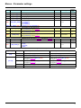
Name
O21
[FSPD_C]
Crane high speed reference
m/s
0.000 to 4.000
0.800
O22
[LSPD_C]
Crane low speed reference
m/s
0.000 to 4.000
0.300
O23
[FSPD_T]
Trolley high speed reference
m/s
0.000 to 4.000
0.500
O24
[LSPD_T]
Trolley low speed reference
m/s
0.000 to 4.000
0.150
-
0 to 2
0
O25
Function
Unit
Choice of load cable acquisition method:
0: [2 switches]
[ACQ_CBL_CONF]
1: [encoder]
2: [3 switches]
Range
Factory
setting
Code
[ACQ_CBL_CONF] (O25) = [2 switches] (0) or [3 switches] (2)
O26
[HIGH_POS]
High position for load cable length.
See [2 switches] method page 15
m
0.00 to 25.00
0.00
O27
[MIDD_POS]
Mid position for load cable length.
See [2 switches] method page 15
m
0.00 to 25.00
0.00
O28
[LOW_POS]
Low position for load cable length.
See [2 switches] method page 15
m
0.00 to 25.00
0.00
O29
[LOAD_LENGTH]
Additional length. See figure 7 page 15 and figure 8 page 16.
m
0 to 5
1
O30
RESERVED
-
-
-
-
Selection of speed reference source.
0: [LI3]
1: [LI3 4 5]
2: [AI1]
-
0 to 2
0
O31
[RQ_CONF] (1)
(1) This parameter must be modified only when the drive is stopped. The following table shows the different configurations possible.
[RQ_CONF] (O31)
[LI3]
[LI3 4 5]
[AI1]
Input
Speed reference for crane
Speed reference for trolley
LI3 = 0
Low speed [LSPD_C] (O22)
Low speed [LSPD_T] (O24)
LI3 = 1
High speed [FSPD_C] (O21)
High speed [FSPD_T] (O23)
LI3 = 1
Crane preset speed 3 [SP3_C] (O39)
(see figure 15 page 29)
Trolley preset speed 3 [SP3_T] (O41)
(see figure 15 page 29)
LI4 = 1
Crane preset speed 4 [SP4_C] (O40)
(see figure 15 page 29)
Trolley preset speed 4 [SP4_T] (O42)
(see figure 15 page 29)
LI5 = 1
High speed [FSPD_C] (O21)
High speed [FSPD_T] (O23)
Crane speed request
Trolley speed request
AI1
27
Menus - Parameter settings
Code
Name
Function
Unit
Range
Factory
setting
1: Factory setting of menu 1.14
0: This parameter is reset to 0 once the return to factory settings
is complete.
Note: A return to factory settings also clears all the data
stored in the memory (of all activated switches)
O32
WARNING
[FACTORY_SET]
-
0 to 1
0
UNINTENDED EQUIPMENT OPERATION
Return to factory settings when the bridge is between
two switches.
Failure to follow this instruction can result in
death, serious injury or equipment damage.
O33
[TBE_C]
Time delay after anti-sway effect. Value of brake time delay.
New value of this parameter is effective when the user changes s
from no anti-sway (LI51 = 0 V) to anti-sway mode (LI51 = 24 V).
0.00 to 2.00
0.10
O34
[TBE_T]
Time delay after anti-sway effect. Value of brake time delay.
New value of this parameter is effective when the user changes s
from no anti-sway (LI51 = 0 V) to anti-sway mode (LI51 = 24 V).
0.00 to 2.00
0.10
O35
RESERVED
-
-
-
-
O36
[MIN_LEN_CBL]
Minimum cable length. Cable length at the up position
Note: A wrong value can cause sway.
m
0.05 to 5.00
0.50
O37
[MAX_LEN_CBL]
Maximum cable length. Cable length at the bottom position
Note: A wrong value can cause sway.
m
3.00 to 40.00
5.00
m
0.001 to 65.535
0.001
[ACQ_CBL_CONF] (O25) = [encoder] (1)
O38
28
[RES_ENC]
Encoder resolution. Length of cable during calibration
See [encoder] (1) method page 14
Note: A wrong value can cause sway.
Menus - Parameter settings
Code
Name
Function
Unit
Range
Factory
setting
[RQ_CONF] (O31) = [LI3 4 5]
O39
[SP3_C]
Crane preset speed 3 (see figure 15)
m/s
0.000 to 4.000
0.000
O40
[SP4_C]
Crane preset speed 4 (see figure 15)
m/s
0.000 to 4.000
0.000
O41
[SP3_T]
Trolley preset speed 3 (see figure 15)
m/s
0.000 to 4.000
0.000
O42
[SP4_T]
Trolley preset speed 4 (see figure 15)
m/s
0.000 to 4.000
0.000
CAUTION
UNINTENDED EQUIPMENT OPERATION
For preset speed parameters ([SP3_C] (O39), [SP4_C] (O40), [SP3_T] (O41), [SP4_T] (O42),
choose a value greater than the low speed reference ([LSPD_C] (O22), [LSPD_T] (O24)).
Failure to follow this instruction can result in injury or equipment damage.
Speed (m/s)
[FSPD_C] (O21)
[SP4_C] (O40)
[SP3_C] (O39)
[LSPD_C] (O22)
Logic input
LI1 or LI2
LI3
LI4
LI5
Figure 15
29
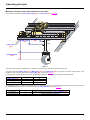
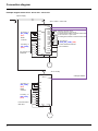
Connection diagram
Example diagram with 2 ATV71 drives and 1 crane card
3-phase supply
Q
According to
[RQ_CONF]
(O31)
Brake
contactor
According to
[RQ_CONF]
(O31)
Forced local and
fault reset
ATV71 Crane + crane card
L1-L2-L3
ATV71 + VW3A3510
CAN
CAN
LI51
COM
LI52
LI53
AI1+
LI54
LI55
+10
LI56
R2A
LI57
LI58
R2C
LI59
LI60
LI1
LO51
LI2
LO52
LI3
LI4
LI5
LI6
Assistance activation switch
T. end limit switch on right and left
T. slowing down switch on forward and reverse
C. end limit switch on right and left
C. slowing down switch on forward and reverse
According to
[ACQ_CBL_CONF] (O25)
Active assistance indicator
Error indicator
COM
P24
24 V
U-V-W
M1
ATV71 Trolley
Q
L1-L2-L3
ATV71
CANopen fieldbus
CAN
COM
According to
[RQ_CONF]
(O31)
AI1+
Brake
contactor
+10
R2A
R2C
According to
[RQ_CONF]
(O31)
LI1
LI2
LI3
LI4
Forced local and
fault reset
LI5
LI6
24 V
U-V-W
M2
30
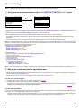
Commissioning
Steps 1 to step 5 must be followed before installing the crane card and activating anti-sway assistance.
1 - Configure the motor parameters via the [1.4 MOTOR CONTROL] (drC-) menu
RDY
App
+0.00Hz
MAIN MENU
1 DRIVE MENU
2 ACCESS LEVEL
3 OPEN / SAVE AS
4 PASSWORD
5 LANGUAGE
Code
REM
RDY
ENT
T/K
App
+0.00Hz REM
1 DRIVE MENU
1.1 SIMPLY START
1.2 MONITORING
1.3 SETTINGS
1.4 MOTOR CONTROL
1.5 INPUTS / OUTPUTS CFG
Code
<<
>>
T/K
• Enter data from the motor rating plate in the menu: [Standard mot. freq] (bFr) - [Rated motor power] (nPr) - [Rated motor volt.] (UnS)
- [Rated mot. current] (nCr) - [Rated motor freq.] (FrS) - [Rated motor speed] (nSP) parameters.
• Perform an auto tune operation [Auto tuning] (tUn) at least once, with a result = OK.
The final integrator/user must know the corresponding linear speed for the motor running at nominal frequency:
• For example, if the linear crane speed is 1,889 m/s, the accuracy of this information is critical to obtain the best results for anti-sway
assistance
• Of course, this information must be known on both axes: trolley and crane (as it is used to obtain 2 different values).
Note: For cranes equipped with 2 motors mounted in parallel on the same drive, pay special attention to the result of the auto-tuning
operation. If possible, perform auto tuning with one motor only to be absolutely sure of the slip compensation, etc. You can then add the
other motor and correct the new nominal current/power, e.g.:
Suppose we have 2 identical motors with this plate:
• [Rated motor speed] (nSP) = 1385 rpm
• [Rated motor freq.] (FrS) = 50 Hz
• [Rated mot. current] (nCr) = 1 A
• [Rated motor power] (nPr) = 0.18 kW
Proceed as follows:
• Enter these parameters in the drive menu [1.4 MOTOR CONTROL] (drC-)
• Wire one of the 2 motors
• Perform an auto tune operation [Auto tuning] (tUn)
• Turn the system OFF
• Wire the second motor
• Do not perform auto tuning this time
• Correct the following parameters:
- [Rated mot. current] (nCr) = 2 A.
- [Rated motor power] (nPr) = 0.36 kW
Note: If one of the motors is much newer in comparison to the other one (in the case of a maintenance operation, for example), you can
ignore this recommendation and perform auto tuning with both motors wired.
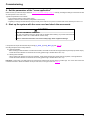
2 - Wiring the crane card and the application part
• Wire and deactivate all slowing down and end limit switches (LI52, LI53, LI54 and LI55 = 24 V). In case of this instruction is not followed,
a start order will cause a [Fast stop] (FSt).
• Insert the crane card into one of the ATV71 drives present (trolley, crane, or possibly hoist).
• Wire up the connections and check the new wiring.
For the crane card wiring part
• The wiring must be perfect on the card, as shown in the diagram on page 30.
• The wiring must be done according to the customer installation:
- Example 1: If a user needs an encoder for high accuracy of the cable load measurement, LI58, LI59 and LI60 do not have the same
function as for a solution based on 3-switch load length detection.
- Example 2: The end limit switches and slowing down switches must be wired according to the recommendations (see page 17).
For the drive wiring part
In the case of an existing crane system, only some of the wires (depending on requirements) have to be added before installing the crane
option card. None of the existing system will have to be changed:
- Example 1: If the user has a joystick preset speed system, LI1, LI2, LI3, LI4 and LI5 have to be wired before you install the crane card.
- Example 2: If the user has a 2-wire method of selecting low/high speeds, wire LI1, LI2 and LI3 before you install the crane card.
- Example 3: If LI6 was used as a force local command/fault reset, LI6 will continue to be used in the same way.
31
Commissioning
3 - Establish the CANopen connection
Connection accessories should be ordered separately (please consult our catalogs). See below.
Reference on diagram
A
B
Description
CANopen connector
9-way female SUB-D connector with line terminator (can be deactivated)
CANopen tap
Catalog number
TSX CAN KCD F180T
VW3 CAN TAP2
CANopen drop cable
VW3 CAN CARR
2 RJ45 connectors
CANopen adaptor to be installed in the RJ45 port in the drive’s control
terminals. The adapter provides a 9-way male SUB-D connector conforming VW3 CAN A71
to the CANopen standard (CIA DRP 303-1)
C
D
..
• Connect the CANopen links.
• Check the global topology and wiring if necessary.
All connectors and wires must be Schneider referenced equipment.
1 CANopen connector (to be plugged into the crane card connector, as well as the ATV71 Hoist if present)
A
on
off
Check that:
- The white wire is connected to CAN_L (CAN_L bus line)
- The blue wire is connected to CAN_H (CAN_H bus line)
- The black wire is connected to GND (ground)
- Impedance checking is set via the external switch ("ON" for Controller Inside)
2 CANopen tap (to be plugged in between the crane card and the drives), with correct internal wiring and impedance selector switch.
B
Check that:
- The white wire is connected to CAN_L (CAN_L bus line)
- The blue wire is connected to CAN_H (CAN_H bus line)
- The black wire is connected to GND (ground)
- Impedance checking is set via the internal switch ("ON" in CANopen tap)
32
Commissioning
3 RJ45 links, between each drive and the CANopen tap (VW3 CAN CA RR03 - 0.3 m or VW3 CAN CA RR1 - 1 m)
1
C
4
2
3
Examples of correct links:
1: Connection to crane drive
2: Connection to trolley drive
3: Connection to crane card
4: Optional connection to hoist drive if present
4 Finally, once all the hardware has been set up correctly as described above, you can start up the system and crane card.
The crane card is equipped with five LEDs which can be seen through the window in the Altivar 71 cover.
The 1.1 CANopen RUN LED must be on steadily, after flashing for a few seconds. If this is not the case, the system will not function properly
(with or without anti-sway assistance)
1.1 CANopen RUN
1.2 CANopen ERROR
1.3 Power
1.4 Application
1.5 Watchdog
LED
Color
1.1 CANopen RUN
Green
1.2 CANopen ERROR Red
State
Off
Flashing
On
Off
Meaning
CANopen master in STOPPED state
CANopen master in PRE-OPERATIONAL state
CANopen master in OPERATIONAL state
No CANopen error
The CANopen master error counter has reached or exceeded its warning level
1 flash per second
(too many errors)
Node Guarding error (vis-à-vis a CANopen slave) or Heartbeat error (CANopen
2 flashes per second
master acting as consumer)
On
The CANopen master is in the "OFF" state.
33
Commissioning
The global CANopen wiring can be as follows:
Hoist
Crane
Trolley
D
VW3 CAN A71 (1)
+
Crane card
VW3 A3 510
Note: Don't forget that the crane card can be plugged in to any ATV71 drive (hoist, crane or trolley) without making any difference to crane
application behavior.
(1) This adaptor is necessary if a hoist drive is present.
34
Commissioning
4 - Set the parameters of the "crane application"
Make sure that you follow the steps outlined in “Menus - Parameter settings”, page 21 carefully, including the settings for the drives as well
as those specific to the crane card.
Typical user parameter errors include:
- Incorrect linear speed (of crane and/or trolley)
- Ramps too short in crane card menu (it depends on each crane)
- Forgetting to change the internal drive ramps (normally set to minimum 0.1s) due to confusion with crane card ramps in menu 1.14
5 - Start up the system with the crane card and check the movements
CAUTION
RISK OF EQUIPMENT DAMAGED
The user must wait that the logic output LO52 is activated before making any vertical and horizontal
movements. LO52 = 24 V means that the crane is ready.
Failure to follow this instruction can result in bodily injury and/or equipment damage.
It is important to respect the selected ramps exactly: [T_ACC1_x] and [T_DEC1_x] (see page 25).
Checking all aspects of the safety switches:
•For end limit switches:
- When reaching the end limit switch on both axes and sides, check that movements are stopped without quick ramps (no linear ramps).
- Check that sensor switches are wired and set correctly (positive logic: activated when set to 0 V).
•For slowing-down switches:
- When reaching the switches on both axes and sides, check that movements are slowed down as expected, in the right direction.
- Check that sensor switches are wired and set correctly (positive logic: activated when set to 0 V).
Important: In both cases, end limit switches or slowing down switches are wired in series in positive logic. The crane card records the
movement direction to determine whether to stop or slow down, move right or left. See page 19.
35
Commissioning
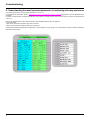
6 - Understanding the most important parameters for activating anti-sway assistance
This section gives advice on some of the parameters in menu 1.14.
It complements the information given in “Parameters in the [1.14 Crane] (SPL-) menu”, page 25 and provides some real application case
examples.
For ease of comprehension, examples are based on screen shots of Codesys menus, which show an exact copy of the Oxx parameters in
menu 1.14.
Each scope measurement is done with trolley/crane axes simultaneously for easy comparisons.
In all scope traces:
- Red curves represent the speed image of the crane axis
- Black curves represent the speed image of the trolley axis
We start with the following application configuration. In each example, we only change 1 or 2 parameters at a time to be able to determine
their impact more clearly.
36
Commissioning
Parameters [T_ACC1_x] and [T_DEC1_x] (see page 25)
These parameters define the manual time to reach maximum linear speed from 0 m/s (manual means anti-sway assistance not active,
LI51 = 0 V).
From these parameters we are also able to deduce the automatic ramp adaptation applied when assistance is active.
Modification of these 2 parameters:
With anti-sway assistance
Without anti-sway assistance
Crane speed
Crane speed
1
Trolley speed
Trolley speed
1
Conclusion: The time to obtain the ramps, if assistance is active, is more or less the same for both trolley and crane here, due to the need
to have no sway. In fact, [T_ACC1_x] and [T_DEC1_x] have significant effects only in manual mode (no assistance). The impact is also
visible from the shape of the curves if assistance is "ON" (see 1).
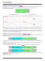
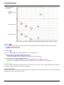
Parameters [V_ACT_C] (O07) and [V_ACT_T] (O17) (see page 25 and page 26)
Developed for a customer who required no anti-sway assistance, for very short or slow movements, even if anti-sway assistance is active
(LI51 = 24 V)
Consider the example below, where only the following values are changed on the trolley and crane:
The unit of [V_ACT_C] (O07) and [V_ACT_T] (O17) is expressed as a %. It is a percentage of [VMAX_C] (O01) and [VMAX_T] (O11)
respectively.
For the purposes of this demonstration, we are simulating a situation of high cable length value, so as to be able to illustrate the effect of
anti-sway on the ramps as clearly as possible.
These parameters are not changed in the basic configuration (see page 36) but are important to understand this demonstration:
The selected speed reference for this test is low speed for each axis (LI1 only) to show the impact of the [V_ACT_C] and [V_ACT_T]
parameters (as shown in the parameter settings above):
[LSPD_C] (O22) = 0.3 m/s
[LSPD_T] (O24) = 0.3 m/s
37
Commissioning
LI1 action on
crane drive
Crane speed (Hz)
1
1
3
4
2
3
4
LI1 action on
trolley drive
Trolley speed (Hz)
2
LI3 action on
crane drive
LI3 action on
trolley drive
Conclusion 1
Here, [V_ACT_C] (O07) has no effect on the crane: the anti-sway function modifies the ramp as soon as possible from 0 m/s, because
=> [V_ACT_C] (O07) (20% of [VMAX_C] (O01): 1.0 m/s) = 0.2 m/s.
=> 0.2 m/s < [LSPD_C] (O22) (0.3 m/s).
Because the initial reference is [LSPD_C] (O22) (LI1 of crane alone) at this point on the curve
=> the ramp at this point is not linear: corrected by anti-sway assistance
2
Conclusion
Here, [V_ACT_T] (O17) has an effect on the trolley: the anti-sway function modifies the ramp only above 45% of [VMAX_T] (O11):
=> [V_ACT_T] (O17) (45% of [VMAX_T] (O11): 1.0 m/s) = 0.450 m/s
=> 0.450 m/s > [LSPD_C] (O22) = 0.3 m/s.
Because the initial reference is [LSPD_T] (O24) (LI1 of trolley alone) at this point on the curve
=> the ramp at this point is linear: not corrected by anti-sway assistance.
Conclusion 3
Here, [V_ACT_C] (O07) and [V_ACT_T] (O17) have no effect at all on the crane or trolley:
The ramps start with a speed reference much higher than [V_ACT_C] (O07) and [V_ACT_T] (O17) (the reference required is high speed
for both axes ([FSPD_T] (O23) and [FSPD_C] (O21)) with LI1 and LI3 active respectively in both axes.
Conclusion 4
Here, [V_ACT_C] (O07) and [V_ACT_T] (O17) have no effect at all on the crane or trolley:
This is finishing a movement which had already reached the maximum speed. It is not a short movement; anti-sway assistance remains
effective up to the end of the movement.
GLOBAL CONCLUSION:
1) Let [V_ACT_C] (O07) and [V_ACT_T] (O17) = 0% by default, if you want anti-sway assistance always to correct the ramps (if assistance
is activated with LI51).
2) If the bridge often requires very small movement (small distances done by operator), the bridge will be more reactive, with only a little
sway effect => this depends on the expected behavior required by the end user.
38
Commissioning
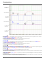
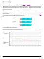
Parameters [T_END_x] and [V_END_x] (see page 25 and page 26)
These are used to reach a compromise between how much time the anti-sway assistance function needs to carry out a movement and the
tolerance required for the final sway effect to become more rigid.
In this example, we only change the following values on the trolley and crane:
The unit of [V_END_C] (O09) and [V_END_T] (O19) is expressed as a %. It is a percentage of [VMAX_C] (O01) and [VMAX_T] (O11)
respectively.
The unit of [T_END_C] (O10) and [T_END_T] (O20) is expressed in milliseconds.
For the purposes of this demonstration, we are simulating a situation of high cable length value, so as to be able to illustrate the effect of
anti-sway on the ramps as clearly as possible.
These parameters are not changed in the basic configuration (see page 36) but are important to understand this demonstration:
The demonstration is:
- Starting from max. speed (on both axes)
- Request a normal stop (LI1 trolley and crane = 0 V at same time)
- Observe the impact at the end of the movement (near complete stop of each axis)
39
Commissioning
Anti-sway assistance
always active
Anti-sway
assistance output
(LO51)
3
1
Crane speed (Hz)
1
2
1
Trolley speed (Hz)
1
1
2
1
Conclusion
1
Both axes illustrate the same behavior, because both drives are configured identically here. But neither drive has yet reached the:
- [V_END_C] (O09) speed for crane
- [V_END_T] (O19) speed for trolley
Conclusion
2
The impact of the [V_END_x] and [T_END_x] parameters occurs during this period.
- We can see that the trolley stopped very quickly, before the crane:
- Because the axis reached the [V_END_T] (O19) speed
- It remained at [V_END_T] (O19) for sufficient time [T_END_T] (O20) before stopping.
- We can see that the crane stopped later than the trolley:
- Because the axis reached the [V_END_C] (O09) speed ([V_END_C] (O09) < [V_END_T] (O19)) later
- It didn't remain at [V_END_T] (O19) for sufficient time [T_END_C] (O10) before stopping only after oscillations.
Conclusion
3
If an external system evaluated the assistance activity (level of output LO51), this output is low (0 V) only when all anti-sway assistance
corrections are completed on all axes (up to the next start order).
GLOBAL CONCLUSION:
These parameters must be tested if the end user wants more or less rigid behavior at each end of the movement. It can be done separately
and differently on each drive (trolley and/or crane).
40
Commissioning
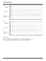
Parameters [V_ASW_C] (O08) and [V_ASW_T] (O18) (see page 25 and page 26)
These parameters are used to adjust the level of comfort of behavior during ramp corrections. They have to be evaluated in situ (each case
differs depending on the bridge) as the resulting action has to be "felt" by the end user. This could change the quality of the final result of
assistance corrections ("no sway" quality) at the end of the movements.
Advantages of these parameters:
1 In the case of an onboard operator cabin (on the bridge), enhanced operator comfort on the seat when the crane is moving
2 Mechanically, the constraints due to different acceleration/deceleration profiles can be modified.
Disadvantages of these parameters:
- They can increase the total time of assistance correction. A compromise must be found between the level of user comfort and the quality
of anti-sway assistance.
The test is illustrated on the crane axis only (the behavior is the same on the trolley axis). Starting from the basic configuration (see page
36), we are comparing the value of [V_ASW_C] (O08) on the crane axis only:
Curve 1
Curve 2
Curve 3
The unit of [V_ASW_C] (O08) is expressed as a %.
For the purposes of this demonstration, we are simulating a situation of high cable length value, so as to be able to illustrate the effect of
anti-sway on the ramps as clearly as possible (anti-sway always active).
Curve 1
LI1 action on
crane drive
Crane speed (Hz)
Anti-sway
assistance output
(LO51)
41
Commissioning
Curve 2
LI1 action on
crane drive
Crane speed (Hz)
Anti-sway
assistance output
(LO51)
Curve 3
LI1 action on
crane drive
Crane speed (Hz)
Anti-sway
assistance output
(LO51)
Global conclusion:
For 100%: The amplitude of the total speed variation is ~14 Hz; the behavior is the most rigid.
For 65%: The amplitude of the total speed variation is ~12 Hz; the behavior is between rigid and smooth.
For 55%: The amplitude of the total speed variation is ~6.5 Hz; the behavior is the smoothest.
42
Commissioning
7 - Slowing down switch and end limit switches
Particularity of end limit switches
If 1 or 2 end limit switches are activated (0 V) at a moment when the crane makes no movement, the card considers that both switches are
truly activated for reasons of safety.
Consequence: The axis is locked, until the limit switches are deactivated.
Particularity of slowing down switches
If 1 or 2 slowing down switches are activated (0 V) at a moment when the crane makes no movement, the card considers that both switches
are truly activated for reasons of safety.
Consequence: The axis can move only at low speed ([LSPD_x]), until the limit switches are deactivated.
For the purposes of all switch demonstrations, the measured cable length remains at 15 m, so as to be able to illustrate as clearly as possible
whether or not anti-sway assistance has an effect.
Conventions:
• S1: End switch of crane for forward direction
• S2: End switch of crane for reverse direction
• L1: Slowing down switch of crane for forward direction
• L2: Slowing down switch of crane for reverse direction
We are using the basic configuration as our starting point (see page 36).
Note: In the 4 curves on the following pages, note that it is the state (TRUE or FALSE) which is represented.
For example:
• If S1 switch state = TRUE, then the corresponding logic input LI54 is active (LI54 = 0 V).
• If S1 switch state = FALSE, then the corresponding logic input LI54 is disabled (LI54 = 24 V).
43
Commissioning
Anti-sway active
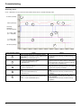
Curve 1: Behavior if we move the crane axis forward, with S1 and L1, and with anti-sway active.
LI1 action (forward)
Crane speed (Hz)
1
4
1
2
5
3
Anti-sway
assistance
corrections activity
4
S1 switch state
(0 V = activated)
L1 switch state
(0 V = activated)
3
LI2 action (reverse)
Curve reference number
1
2
3
44
5
2
4
Action
Result
Start in forward direction (LI1) at maximum speed
(LI3). The crane axis position between switches at the The axis follows the anti-sway corrections during
acceleration.
beginning is:
S1, S2, L1 and L2 deactivated (24 V)
The axis decelerates temporarily without anti sway
The crane axis reaches the L1 switch:
corrections. Once the system reaches or falls below
S1, S2 and L2 deactivated (24 V)
the low speed value, anti-sway corrections continue to
L1 activated (0 V)
have an effect but in a different way.
The crane axis continues and reaches the S1 switch: Anti-sway effects are zero, the system applies a quick
S2 and L2 deactivated (24 V)
stop order (internal quick stop of drive). The system
S1 and L1 activated (0 V)
stops the axis as quickly as possible.
4
Go back in reverse direction (LI2), maximum speed
(LI3):
S1, S2 and L2 deactivated (24 V)
L1 activated (0 V)
5
The crane axis continues and leaves the S1 switch
area:
S1, S2, L1 and L2 deactivated (24 V)
The axis can restart in the other direction at maximum
speed.
The axis follows the anti-sway corrections during
acceleration.
The slowing down switch area is also left. There is no
effect on anti-sway, because the run order is for
reverse operation.
The axis follows the anti-sway corrections during
acceleration.
Commissioning
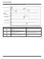
Curve 2: Behavior if we move the crane axis forward, with S1, and with anti-sway.
LI1 action (forward)
1
2
Crane speed (Hz)
3
1
Anti-sway
assistance
corrections activity
S1 switch state
(0 V = activated)
2
L1 switch state
(0 V = activated)
LI2 action (reverse)
3
Curve reference number
1
2
3
Action
Start in forward direction (LI1) at maximum speed
(LI3). The crane axis position between switches at the
beginning is:
S1, S2, L1 and L2 deactivated (24 V)
The crane axis reaches the S1 switch (L1 remains
disabled, due to incorrect wiring, for example):
L1, S2 and L2 deactivated (24 V)
S1 activated (0 V)
Result
The axis follows the anti-sway corrections during
acceleration.
Anti-sway effects are zero, the system applies a quick
stop order (internal quick stop of drive).
The system stops the axis as quickly as possible.
Go back in reverse direction (LI2) at maximum speed
The axis follows the anti-sway corrections during
(LI3):
acceleration.
S1, S2, L1 and L2 deactivated (24 V)
45
Commissioning
Anti-sway not active
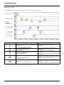
Curve 3: Behavior if we move the crane axis forward, with S1 and L1, and without anti-sway.
LI1 action (forward)
Crane speed (Hz)
1
1
5
2
3
4
Anti-sway
assistance
corrections activity
S1 switch state
(0 V = activated)
L1 switch state
(0 V = activated)
1
2
3
4
5
46
5
2
4
LI2 action (reverse)
Curve reference number
4
3
Action
Result
Start in forward direction (LI1) at maximum speed
(LI3). The crane axis position between switches at the The axis follows the ramps linearly during
acceleration.
beginning is:
S1, S2, L1 and L2 deactivated (24 V)
The crane axe reaches the L1 switch:
S1, S2 and L2 deactivated (24 V)
L1 activated (0 V)
The axis decelerates linearly, without anti-sway
corrections.
The axis falls until it reaches low speed.
The system applies a quick stop order (internal quick
The crane axis continues and reaches the S1 switch:
stop of drive).
S2 and L2 deactivated (24 V)
The system stops the axis as quickly as possible (here
S1 and L1 activated (0 V)
less than 1s)
Go back in reverse direction, maximum speed (LI2 +
The axis can restart in the other direction at maximum
LI3):
speed.
S1, S2 and L2 deactivated (24 V)
The axis follows the linear acceleration.
L1 activated (0 V)
The slowing down switch is also left. There is no effect
The crane axis continues and leaves the L1 switch
on anti-sway, because the run order is for reverse
area:
operation.
S1, S2, L1 and L2 deactivated (24 V)
The axis follows possible ramps, but always linearly.
Commissioning
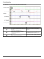
Curve 4: Behavior if we move the crane axis forward, with S1, and without anti-sway.
LI1 action (forward)
Crane speed (Hz)
1
3
2
1
Anti-sway
assistance
corrections activity
S1 switch state
(0 V = activated)
2
3
L1 switch state
(0 V = activated)
3
LI2 action (reverse)
Curve reference number
1
2
3
Action
Start in forward direction (LI1) at maximum speed
(LI3). The crane axis position between switches at the
beginning is:
S1, S2, L1 and L2 deactivated (24 V)
The crane axis reaches the S1 switch (L1 remains
disabled, due to incorrect wiring, for example):
L1, S2 and L2 deactivated (24 V)
S1 activated (0 V)
Result
The axis follows the ramps but linearly during
acceleration.
Even from max. speed, the system applies a quick
stop order (internal quick stop of drive).
The system stops the axis as quickly as possible.
Go back in reverse direction (LI2) at maximum speed
The axis follows the linear ramp during deceleration.
(LI3):
S1, S2, L1 and L2 deactivated (24 V)
47
atv71_Crane_Card_EN_V2
2008-05