1
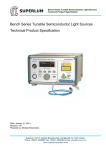
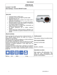
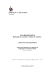
FLIER ESC for Airplane 2S to 22S FLIER ESC for Airplane User’s Manual www.fliermodel.com Tel:+86-0755-27905140 Business: [email protected] Technical support: [email protected] Sales: [email protected] [email protected] Skype: Fliermodel 2S to 22S FLIER ESC for Airplane 2S to 22S ESC for Airplane Manual Thank you for purchasing our products! For the high power of this brushless system, failure to use may result in injury yourself and damage of the whole device. So we highly recommend you to read carefully and abide by the operating procedures of this manual before the first flight. Flier is not responsible for your misuse of this product, or any damage including incidental losses or indirect losses you may cause. Moreover, we have not any responsibility for the modification of our products without authorization. We have the right to change the design, features, functions and operating requirement of our products without any advanced notice! Feature 1.Design for Airplane, more functions. 2.Battery voltage from 2S to 22S for super high voltage version. 3.Two way communication while connecting it with computer. 4.Firmware can be upgraded by the user. 5.Simply set function value by Prog-Box or by PC via USB link wire. 6.Li-MH/Li-Po, Ne-Cd/Ne-MH, LiFe battery can be applied. 7.Enables setting the voltage per cell for the point at which the controller’s cut off circuitry engages.Li-MH/Li-Po from 2.0-3.6V,Ne-Cd/Ne-MH 0.4-1.0V,LiFe from2.2-2.8V . 8.Timing settings may be adjusted (0°-30°)per degree to suit the motor type 9.Three types of throttle curve . 10.Automatically detection the throttle range or can be set a fixed value by manual operation. 11.Auto cut off the power within 3 seconds if no radio signs. 12.6 levels break system. Function Value 1.Brake: Off, Extra soft, soft medium, Hard, Extra Hard.. www.fliermodel.com - 1 - FLIER ESC for Airplane 2S to 22S 2.Timing:0°, 1°, 2°, 3°, 4°……30°。 3.Frequency: 8KHz, 16 KHz, 32 KHz. 4.Acceleration: Soft / Medium / Hard。 5.Accumulator type:NiCd/NiMh, Li-Ion/Li-Pol, LiFe。 6.NiCd/NiMH CUTOFF:×0.05, 0.4V, 0.5V, 0.6V, 0.7V, 0.8V, 0.9V, 1.0V。×0.05 means the cut off voltage is 5% the voltage while connecting. 7.Number of cells: Auto, 2S, 3S, 4S, 5S, 6S, 7S, 8S, 9S, 10S, 11S, 12S, 16S, 17S, 18S, 19S, 20S, 21S, 22S, 23S, 24S. 8.LiIo/Pol CUTOFF:2.0V, 2.1V, 2.2V, 2.3V, 2.4V, 2.5V, 2.6V, 2.7V, 2.8V, 2.9V, 3.0V, 3.1V, 3.2V, 3.3V, 3.4V, 3.5V, 3.6V。 9.LiFe cutoff:2.2V, 2.3V, 2.4V, 2.5V, 2.6V, 2.7V, 2.8V 10.Cut Off Type::Slow down, Hard。 11.Ini point:Auto, fixed 1.0mS, fixed 1.1mS, fixed 1.2mS, fixed 1.3mS, fixed 1.4mS, fixed 1.5mS。 12.End point:Auto, fixed 1.7mS, fixed 1.8mS, fixed 1.9mS, fixed 2.0mS。 13.Throttle curve: Logarithmical, Linear, Exponential。 14.Rotation direction: Left, Right. 15.Timing monitor (TIMING MONTITOR): ON, Off. Note:the red mark is the factory default value。 Diagram for wire connection 1. Correctly connect ESC to brushless motor, receiver and battery pack(correctly use the Anti-spark wire while connect the ESC to battery pack). 2. Electronics are correctly power on for the setting 3. Then you will hear or 。(if you don’t hear the first three beeps, pls check your motor, whether the motor wires is connected well or not. The last one beep means the ESC enter to forward mode, the last two beeps means the esc enter to forward and reverse mode, if you can’t hear the last one beep or two beeps, pls check your receiver, whether it’s connected well or not, and check your remote control). 4. Pushing the trigger, then the motor will start to work. Notice: Correctly use the anti-spark wires. The anti-spark wire including a bullet connector and an anti-spark resistor. So you can separate it into two wires. You must solder the another one to the battery negative. If you want to connect the ESC to the battery, you can connect the red wire of ESC to the positive pole of battery at first. Then connect the anti-spark wires well. The last step is connect the black wire of ESC to the battery’s negative pole. If do like that, no spark will be generated, and it will protect the main bullets connector from damaged. www.fliermodel.com - 2 - FLIER ESC for Airplane 2S to 22S Function value setting by transmitter www.fliermodel.com - 3 - FLIER ESC for Airplane 2S to 22S Group” ♪”(Bra ke On Mode) or”♪♪” (Brake Off Mode) Param eter Saved and Exit Progra mming Mode This series ESC can be set some simple function value by transmitter, but the more function value setting must be by prog-box or PC via USB link wire。 This ESC gets two different types of mode, one is Brake ON mode, and another is Brake Off mode. Change mode setting procedure as follows: 1.Move throttle stick on full power position, turn on transmitter. Now when switching on the ESC, programming sequence will start. 2.Connect the power battery, turn on receiver. 3.After approx. 5 seconds, a four-tone melody can be heard; this indicates that a programming sequence is ready. 4.And then you will hear 5 groups “♪ (a short beep)”, then 5 groups “♪♪”, then 5 groups “♪♪♪” and then 5 groups“♪♪♪♪” ; and 5 groups “♪”,5 groups “♪-(a long www.fliermodel.com - 4 - FLIER ESC for Airplane 2S to 22S beep)♪”,5 groups “♪♪”. And these sounds of groups will circulate 5.Each group of 5 sounds stands for a different mode of ESC respectively. 6.You can put the throttle stick to the middle position during one group of 5 sounds, and then the corresponding mode is saved. 7.Hear 1“♪”(Forward mode) or "♪♪" (Forward/Reverse mode), then you can exit the setting mode after saving the mode. (When the mode is saved, you can disconnect the ESC to the battery pack) ◎Brake On mode and Brake Off mode: Hear the first “♪♪♪♪”,put the throttle stick to the middle position, the mode is changed from Brake ON mode into Brake off mode. If you want to change back, please repeat the above procedures, and vice versa. ◎Timing(motor ignition advance)function value: 1.Hear 5 groups“♪”or“♪♪”or“♪♪♪”or“♪♪♪♪”in the above circulation, put the throttle stick to the middle position. 2.Timing mode 1: 5 groups “♪”----0~7° (recommended for 2 poles and common motors) 3.Timing mode 2: 5 groups “♪♪”----8~15° (recommended for 4 poles motors) 4.Timing mode 3: 5 groups “♪♪♪”----16~23° (recommended for 8 poles motors) 5.Timing mode 4: 5 groups “♪♪♪♪”----24~30° (recommended for more than 10 poles motors and out runner motors) ◎Setting of Frequency: 1.Hear 5 groups“♪-”or 5“♪-♪”or 5“♪♪”in the above circulation, put the throttle stick to the middle position. 2.Frequency 1: 5 groups “♪-”----8 kHz ((For common setting, the lowest efficiency loses) 3.Frequency 2: 5 groups “♪-♪”----16 kHz (recommended for the low internal resistance of motor) 4.Frequency 3: 5 groups “♪♪”----32 kHz (recommended for the low electrical inductance of motor) Note: when the timing of motor is saved, please adjust motor on the ground before the flight (Diagram for Option parameter assistant by transmitter) Function value setting by Program-Box By the Flier Program Box, you can set all of function value very simply.Setting procedure as follows: 1. Connect the 4pin connector of ESC with the 4PIN connector in Prog-Box. Make sure the direction is correct. www.fliermodel.com - 5 - FLIER ESC for Airplane 2S to 22S 2.Connect ESC and motor. 3. Power on the ESC, and you will hear a “♪♪♪” melody, it prompt that the connecting is ok and you can go on. 4.” Great! Read ESC Data OK”will be displayed on the LCD screen(on the front of the Box). after 1 second, it will enter the first function-MODE TYPE setting interface automatically. Then your esc type can be displayed on the LCD screen. “←” and “→” buttons make no difference because the ESC type can’t be changed. 5. Press “Forward” button to enter the second function item-CONTROLLER TYPE. The ESC type which you purchased will be displayed on the LCD screen. “←” and “→” buttons make no difference because the ESC type can’t be changed. 6. You can press ”Forward” button enter desired function item ,then press ←and→ button enter desired value. You also can press “Back” button, then back to the last function item. 7.All setting is done. The LCD screen will display “Sending Data to ESC” if you press “Back” and “Forward” buttons. It prompt the setting value have sent to the ESC. 8. Turn off the power of the esc, and connect the power. You can inspect whether the function values were wrote in the ESC or not. 9.After setting over, turn off the ESC, disconnect the Prog-Box. Setting is done. Note:if the ESC you are setting is no BEC, you will have to power to the Prog-Box via another 3pin connector Function value setting by PC An excellence in this series ESC is that they can be set function value via PC. By a match software designed our company, via a USB Linker, a ESC can communicate with PC, then you can Easily set the ESC function value on PC screen. www.fliermodel.com - 6 - FLIER ESC for Airplane 2S to 22S If use firstly, you must install the USB Linker driver and the ESC setting software. Installation of USB Linker’ driver The below are the instructions of how to install the driver under Windows XP, 1. Firstly plug the USB linker into the USB port on the computer. The computer will automatically detect the USB linker and ask for installation of the USB driver. The computer screen shows the window “Found new hardware wizard “. Press “Next” button. 2. Please select “Install from a list or special position (Advanced)” and press “Next” button. 3. Please select “Search for the best driver in these locations” and check “Include this location in the search”. In the search dialog specify the location of the USB driver that is located in the CD or driver download folder “USB driver”. 4. The above steps probably need to be repeated. If any same prompt appear, please repeat the installation steps carefully until the installation process is complete. 5. Open Windows Device Manager. (Control panel ¨C system ¨C device manager) 6. Find "Ports (COM & LPT)" in the list and click the “+” sign to its left. 7. Find the line that reads “Prolific USB-to-Serial Comm. Port (COMX)". The "x" value is the COM port number that was assigned to the USB to serial converter. This is the port that will need to be selected in the Flier ESC Computer Linking Software. Make note of it. www.fliermodel.com - 7 - FLIER ESC for Airplane 2S to 22S Note:different computer will have different the number of COM port, remember it, you will use the number in the ESC setting software。 Flier ESC Computer Linking Software Installation The installation of Flier ESC Computer Linking Software is as the same as the normal Windows software. In windows system, you run simplify setup file, and then install it easily according to the prompt. After installation finish, you can run the software. Only after the Flier USB linker connects the Flier ESC to the computer, the software can be operated. Flier ESC Computer Linking Software Interface Overview 1. The top-left of the interface is “Select COM Port”, “ESC type”, this will be for comport select and the Flier ESC type display. 2. The top-middle of the interface is a text box. it can display some messages of the software progress. 3. The middle main area of the interface is the program area. You can program the setting value of the ESC here. 4. The top-right of the interface is a write data button. You can press it to write the setting value into the ESC. 5. The bottom of interface displays the copyright and company website information. How to program the ESC 1. This is very important. Disconnect the battery, the motor and the receiver. I.e. disconnect all connections of the ESC. 2. Launch the Flier ESC Computer Linking Software. You can see a interface which the above mention. Because the Flier ESC is not connected, the interface isn’t operated now. 3. Plug your Flier USB linker into the computer, and if the USB linker driver has been installed correctly. The com port can be automatically selected, the automatic selection usually is right, but some computer have too many com port is using. An error com port selection is possible, in this condition; you must select the correct com port which the www.fliermodel.com - 8 - FLIER ESC for Airplane 2S to 22S above mention. 4. Connect the 4pin wires of the USB linker to the 4pin wires of the ESC, pay attention to the color of the wires, must ensure the same color wires connect together, or you will possibly damage the ESC. If you connect correctly, the Flier ESC type will display in the ESC type column. If don’t display correctly, you can pull the 4pin wires and plug again, till the display is correct. 5. You can see the setting value in the Flier ESC will display the program area. So you can easily know the setting value of the ESC at current. 6. You can change any setting value from the program area; you also can press the “load factory default” text to load the factory default value. 7. After you finish your adjustment. Press the top-right “write” button, your setting value will write into the ESC. 8. Disconnect the 4pin wires, 9. Exit the flier ESC computer software, 10. Pull out the USB liker. Now, your ESC has been programmed. Update the firmware of the ESC 1, Plugging the USB Linker wires ,be sure that the USB linker wires driver was installed, 2 .Running the software, click the "Flash" button. After a "Download ESC type OK"message displays in the text box, you can reboot the software. (The second step must be done, if not, the firmware types which you need for the ESC can't be recognized). 3. Choosing the correct port from "Select COM Port", 4. Choose the firmware which you want, the next step is click "Down Load File" button. "File read OK!".Message will appear. 5. Disconnect the power of the ESC and BEC. 6. Plugging 4pin of the ESC into the 4 pin of USB Linker. "Connect OK, Please....." message www.fliermodel.com - 9 - FLIER ESC for Airplane 2S to 22S will appear. 7.If any errors pull out 4pin wires then repeat step 6 still correct message. 8. Clicking “Write" button. the ESC will be updated software now. 9. Waiting, until "update to 113 pages, errors pages 0.....” tell you the updated software succeed. 10. You can disconnect the 4pin of the ESC from the USB Linker. www.fliermodel.com - 10 -