1
Extending Forth
in a Camac Controlled Muon Channel
Robbie Spruit
TRJUMF
Vancouver, B. C.
Canada, V6T 2A3
Abstract
Control and diagnostic software was developed for a recently commissioned muon channel at
TRIUMF. Logistics gave rise to separate efforts in several programming languages. This paper
describes the Forth diagnostic package. The choice ofprogramrning language is discussed briefly.
Several extensions to Forth, and their usage, are shown in the framework of a detailed account of the
software implementation. Emphasis is placed on the production of readable code and on the design
of constructs that closely model the structure of the application.
Contents: Choice of language; Beam line overview; Channel control; Forth implementation;
Terminal; Camac; Channel elements; Functions; Parameters; User interface; Conclusion; References;
Appendices: CalTech Forth, Non-standard words, Extensions; Source Files: LOAD, VT100,
CAMAC, DIGI, POWER, CONFIG, USER, INFO.
Preface
When the M 15 channel at TRIUMF delivered its first muons, the very fITst channel settings had
been established with the aid of a small Basic program. Subsequent beam tuning was done with a
set of Forth routines, until the adaptation of an existing control program, written in C for another
channel, was completed.
The Basic program was coded in six hours. It was less than two pages and permitted the
checking of the cabling and of the computer access to the power supply interfaces.
The Forth application routines were developed in three weeks, took seven pages and allowed
full control and diagnostics.
Adaptation of the C program took a month. This involved adding a few pages to the existing
fifty and some restructuring necessitated by porting to a different operating system and compiler.
This package was not meant for diagnostics. It features a channel definition language and a level of
user interface not addressed by the other programs.
The efforts in the different languages varied widely in scope. They were not undertaken to study
the comparative merits of programming languages but rather to do a specific job with the tools at
hand.
This paper describes the Forth program used for channel tuning and hardware diagnostics. On
several occasions modifications or extensions of the Forth language were introduced to make the
code more readable.
Choice ofLanguage
Clearly, if the task is simple enough, the choice of programming language is less important and
a simple language like Basic can be very effective.
Journal of Forth Application and Research Volume 3, Number 4
3
The Journal of Forth Application and Research Volume 3 Number 4
4
Forth excels in flexibility and speed of implementation but it lacks the wide acceptance and
standardization of C. The choice between Fortran and Forth on technical grounds can be quite clear:
Fortran for math, Forth for control. Include the programming language C and the arguments are less
evident. C is well suited to either type of task.
The advantages of Forth, interactiveness and structural extensibility, were not sufficient reason
to rewrite existing application software. However, when setbacks in the acquisition and installation
of the system software began to jeopardize the timely completion of the C approach, a parallel effort
was started in Forth.
A version of CalTech Forth [2] had already been used on site to run FASTBUS test software
[4] under RSXll-M on a PDP 11/34. Since the control system for M15 was to employ a Micro-ll
with RSXll-M, there were no problems with the installation.
Beam Line Overview
TRIUMF is the name for Canada's meson facility in Vancouver, British Columbia. It is used
for pure research in nuclear and particle physics as well as for applied research programs such as:
a) the treatment of cancerous tumours with pion' beams, b) the production of medical radioisotopes
and c) the use of neutron beams for geological analyses. TRIUMF is operated by the universities
of Alberta, British Columbia, Victoria and Simon Fraser under a contribution from the National
Research Council of Canada.
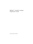
Figure I shows the layout of the 147 m long main building. The six segment cyclotron, 18 m
in diameter, allows the simultaneous extraction, of multiple proton beams at different energies of up
to 520 MeV and 140 uA. Two targets, placed in the;rthorproton beam line 1, are the sources for
a total of six secondary beams of pions and muons.
CHEMISTRY
ANNEX
42 MeV
ISOTOPE
PRODUCTION
CYCLOTRON
MESON
HAll
NEUTRON
ACTIVATION
ANALYStS
SERVICE
ANNEX
EXTENSION
THERMAL
NEUTRON
SERVICE
FACILITY
ANNEX
MESON HAll
Figure 1. Floor plan of the TRIUMF cyclotron building
M15 is a dedicated "surface" muon channel. It collects positively charged muons from pions
decaying at rest within a few microns of the meson production target's surface. Surface muons are
longitudinally spin polarized and may be collected into beams of high optical quality. These
properties are exploited in two categories of experiments: measurements of muon decay to test
modern theories of particles, and muon spin rotation experiments to test physical and chemical
Extending Forth in a Camac Controlled Muon Channel
5
phenomena quite unrelated to nuclear or particle physics. For example, the muon is a sensitive probe
of magnetism in solid state crystals.
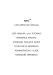
A more detailed mechanical layout of the channel is given in Figure 2. The controllable elements
shown are dipole magnets (benders), BI to B4, which steer the beam and quadrupole and sextupole
magnets, QI to QI7 and SXI and SX2, which are arranged in pairs or triplets to focus the beam.
The two DC separators were not included in the initial installation. Movable slit plates (not shown)
select spectral qualities such as divergence, momemtum range, intensity and spot size.
t
EXPERIMENTAL
TARGET
LOCATION
(EL.291.5')
lATl TARGET
ARRAY
Figure 2. Muon channel MI5
Channel Control
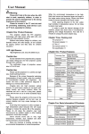
Remotely controllable power supplies provide direct currents of up to 750 Amperes to the
magnet coils. Local interlock circuitry monitors such conditions as magnet temperature and coolant
flow and automatically switches off the corresponding power supply when necessary. Each power
supply has an analogue input to set the current regulator, an analogue output to monitor the actual
output current, digital outputs indicating on, off and interlock status and digital inputs to switch
power on and off and to allow a reset of interlock faults. DIA converters, AID converters and digital
I/O modules housed in a Camac [1] crate provide for computer control as indicated in Figure 3.
The slits are positioned with AC motors, driven by a microprocessor in the same Camac crate,
and interfaced through similar AID and digital I/O modules.
The Journal of Forth Application and Research Volume 3 Number 4
6
COMPUTER
TERMINAL
CAMAC
CRATE
POWER
SUPPLIES
MAGNET
COILS
P.S.
P.s.
P.s.
Q1
Q2
Q17
~ ~MUONS §
~§~
----.------~~
§
~§~
QUADRUPOLE
DIPOLE
SEXlUPOLE
Figure 3. Camac interface connections
Camac, - the phrase 'Computer Automated Measurement And Control' has been adopted to
make it an acronym -, is the name for an instrumentation bus standard which originated in the
nuclear science community.
Extensive experimental calibration (tuning) is required to obtain a beam with particular characteristics. A given beam line tune is best represented by a set of magnetic field strengths.
Monitoring the actual fields with probes may be costly, difficult or impossible. The value given to
the D/A converter that sets the magnet current may provide a suitable measure. Such is the case for
MI5, so that tunes are normally described by a set of DAC settings.
Automatic tuning has, for economic and technical reasons, only recently been given serious
consideration. Integration of the beam line control system with the detector and data acquisition
systems is still in the planning stage.
The type of control considered here is the provision of convenient facilities for setting and
monitoring the state of a number of beam line elements. The interpretation of the detector readout
and the choice of parameters for the elements are operations performed by a beam line physicist.
Forth Implementation
The source code of the application programs is listed in the appendix. The me named LOAD
loads the following mes (VT100, CAMAC, CAMEM, DIGI, POWER, SLITS, CONF IG and USER) on
top of the modified CalTech RSX Forth.
The file CAMEM deals with access and diagnostics for a special Triumf Camac memory module,
while in S LIT S motor control is passed to a microprocessor via a protocol through such a memory
module. These two files have been left out in order to avoid an encumbrance of site dependent trivia.
The type of features they offer and the programming principles they depend on are equally well, or
better, explained with the files DIGI and POWER.
The conceptual design began with a tabular representation of the elements of the muon channel.
This became the file CON FIG. Then the notions of what one wanted to do with the elements were
Extending Forth in a Camac Controlled Muon Channel
7
put in the file POWER, for magnet power supplies, and in the file SLITS for the moveable slit plates.
The files VT100 and CAMAC are general utilities. The user interface in the file USER was held to
a minimum since eventually this would be handled by the existing C software.
The following narrative of the principal design modules is presented in the order in which the
files are loaded.
Terminal
Initially, basic control was developed for a hardcopy terminal mode in which standard Forth
terminal I/O is adequate. Later, software was added to support a 24 x 80 character video display.
A set of cursor commands is grouped in a file named after the terminal type, in this case a
VT100. The word ESC sends an escape sequence made up of the next word and preceded by an
escape character. A generic compilation construct was devised to allow the creation of words such
as ES C, which differ only slightly from regular string output but would normally be awkward to
implement as they are to be used inside as well as outside of definitions. ESC and ." are defined
as follows:
ESC
"
BL ($) 33 EMIT WRITE
& "
($)
WRITE
The definition for ($) was a bit tricky, since it has to cause the word in which it is used to be
state sensitive, but the result is satisfying: it makes it easy to define some very useful words. ESC
makes it possible to code terminal dependent escape sequences in a format that is identical to the
specification in the user's manual. The effect of the sequences can be checked interactively, with no
need for additional definitions.
Camac
A subaddress (A) in a slot (N) in a Camac crate is declared as an addressable entity to which
a maximum of 32 I/O function codes (F) may be applied.
The brevity of the routines presented in the listing derives from a number of simplifications. All
status is polled so interrupt handling is not necessary. Direct access to the memory mapped I/O page,
and the resulting compromise in operating system security, is acceptable. There is only one crate.
Multi-branch, multi-crate addressing was not needed.
The minimum functionality required for this application, a 16-bit read and a 16-bit write, could
be coded in a few lines. The facilities provided here are used in general non-interrupt Camac
applications. Camac error messages can optionally be directed to specific fields on the screen, using
the message facility defined in the terminal file.
The Channel
The description of the channel configuration in terms that suit computer control can be done
with lists or tables showing the hardware (Camac) layout. Software to read and interpret such lists
creates a program data base. Control routines, to be invoked by operator commands, can then be
written to act on these.
The option of 'intelligent constructs' in Forth allows for a particularly elegant presentation. The
central notion is to treat a beam line element as an active entity, characterised by configuration
parameters and by the functions that are expected of it.
Allocation and initialization of configuration and working parameters was done in the CREA TE
part of a class define construct (named PS :) and the functionality of the various command options
in the DOES> part.
The Journal of Forth Application and Research Volume 3 Number 4
8
Functions
Standard Forths define a variable as a routine that pushes an address on the stack. The value
located at this address may then be read (by @) or written (by !). A suggestion by Charles Moore
led to the 'smart variable' which would return its value rather than its address unless preceded by
the word TO in which case it would take on a new value from the stack [3]. The word VAR: is used
to define such variables in this version of Forth. Its implementation relies on a state variable, set by
TO and .reset by the variable.
Extending this concept to our channel elements leads to software designations of elements that
return a value unless told to take on a new value by a 'prefix operator' [5]. The selection of different
functions, such as +TO for incrementing, is implemented using different values of the same state
variable. For power supplies, the words ON, OF F and RESET are treated in the same fashion as TO
and +TO.
For diagnostic purposes it is useful to change the meaning of an element's value. The words
oAC and AD C indicate that the power supply values are to refer to the setting of the 0/A converter
or to the measure of the actual output current obtained through A/D conversion. The words AMPS
and COUNTS indicate whether the values are measured in Amperes or in OAC or AOC counts.
When the interpretation of a value is in doubt, one can always type it explicitly. For example:
25 AMPS TO Q1
35 TO Q2
AOC Q1
• Q2 •
would check the setting of currents to the first two quadrupole magnets.
The words TO, +TO, ON, OFF and RESET refer to a single power supply. The state variable
they affect is implicitly and immediately reset. The words OAC, AOC, COUNTS and AMPS explicitly
set or reset a state and apply to any number of power supplies.
There are instances where one may want to issue a command for a group of power supplies. For
example, once a tune has been established for a momentum of 30 MeV/c, the tune for 27 MeV/c
may be obtained by scaling all fields down by 10 percent. Status display is another example of a
command that could apply to all supplies. To arrive at a tune it is necessary to sweep selected groups
of magnets through certain momentum ranges.
For these cases command names were chosen with a left parenthesis as the last character. These
assign a certain value to a state variable which keeps its value until reset explicitly by a right
parenthesis. Thus
? ( 81 82 83 84 )
shows the status of the first four benders
-10 S ( 81 82 )
scales the first two down ten percent.
and
The implementation of the TO concept originally used simple values for the state variable, 0
as the default value, 1 for TO, and 2 for +TO. With the proliferation of command options, this
method began to stand out as an example of poor software practice: defining the same association
in more than one place and hoping that the definitions agree.
A 'switch' class define construct (named SW:) was implemented as a remedy. It allows the prefix
operators to be defined such that they switch a state or fuction variable to some unique value, in this
case the parameter field address. As can be seen in the definition of PS: in the fIle POWER,
comments are no longer required to identify the commands.
Parameters
In a CREATE DOES> construct the parameter field address is available on the stack when the
part following DOES> is executed. The individual parameters can then be retrieved by applying
offsets to this address.
Extending Forth in a Camac Controlled Muon Channel
9
For power supplies, thelarge number of parameters required to define their state dictated the
creation of a naming convention. The initial approach was to store the parameter field address on
entry after DOES> in a variable, named PAR.
For each parameter then a word was written to access it, e.g
VAR: PAR
DAF
PAR 4 +
: ADF
PAR 8 +
were used to get the address of the full scale values of the DAC and the ADC. These definitions
evolved into variables of the form:
• PAR 4 PAR.OF: DAF
• PAR 8 PAR.OF: ADF
where PA R• 0 F: was such that the parameters now worked with prefix operators, which looked well
since read access was much more common than overwriting.
In the course of development, the number and order of parameters was changed a few times.
Each change required an edit of the offset literals. This was not difficult but there was an awareness
of something not being quite right. PA R• 0 F: was replaced by 'underbar colon', which needs no
arguments. It assumes it is being used in the context of a parameter list accessed via a pointer, called
PAR . The name change of PAR to PAR reflects the change in type, from VAR: to PNT:.
Not only was the readability of the p-;;rameter declarations greatly improved hereby, the way
was opened up for a similar improvement in parameter allocation and initialization. The pointer
declaration, PNT:, was extended to mark the beginning of a data structure, with subsequent
parameter declarations increasing the size. The word ALL 0 CAT E, used in the CREA TE part of a
CREATE DOES> construct, allots space for the parameters and makes them accessible by name.
Thus, allocation and initialization no longer require knowledge of offsets or order of declaration.
User interface
An on-line help facility was added and the software was installed to come up automatically with
a continuous status display after logging in to the operating system.
He Lp consists of a list of the most common command options, the last of which is the command
to reinvoke the display. Thus there is always an indication of what options are available. A minimum
of typing skill is required to switch between display and command mode. When in command mode,
the user has access to the entire Forth command set. This is where this implementation stops being
user friendly. Logically, CalTech Forth's entire dictionary, the assembler included, is just one long
list. Fatal results, even if unlikely, are possible by mistyping.
Early Forth systems have always been criticized for such surprises. There are a number of
possible preventive programming measures. None were pursued, since power prevailed over
protection, and time was of the essence.
Notwithstanding its known drawbacks and pitfalls, this simple user interface is highly effective,
requires a minimal development time, and is immediately aqcessible to unfamiliar users without
hindering the more experienced.
Conclusions
The description of the Forth application program made it possible to present some language
constructs, data and function structures or pseudostructures 'in real life' as extensions to the Forth
language.
10
The Journal of Forth Application and Research Volume 3 Number 4
A concise style of implementing functional descriptions is achieved when individual references
to parameters or structure members may be made without having to refer explicitly to the structure
itself.
Coding prefix format commands by name permits a more readable implementation of constructs
that make use of such operations.
References
[1] Modular Instrumentation and Digital Interface System (CAMAC) ANSI/IEEE Std 583-1975.
[2] M.S. Ewing, The CalTech Forth Manual, June 1978. A Technical Report of the Owens
Valley Radio Observatory, California Institute of Technology, Pasadena, Ca 91125.
[3] P. Bartholdi, The TO solution, and 'TO' continued, FORTH Dimensions, Vol. 1, No. 4/5,
1979.
[4] C. Logg, Fastbus Diagnostic Operating System (FBDOS), Aug 1982. Informal paper,
Stanford Linear Accelerator Center, Ca 94305.
[5] K. Schleisiek, Multiple Code Field Data Types and Prefix Operators, Jml. of Forth Appl.
;& Res. Vol. 1, No.2, Dec 1983.
Manuscript received June 1985.
Robbie Spruit, P.Eng., M.Sc. (Eng) Delft, learned about Forth in 1976, when working on data
acquisition and instrument control systems for an international telescope construction project. As
a member ofthe Forth Standards Team, he took part in the definition ofthe Forth-79 standard. Mr.
Spruit is an independent consultant, based in Vancouver, B. c., Canada, with particular experience
in control, communication and interface systems in engineering and specific environments. Among
his current interests is the application of computer systems to natural language services.
Appendix
CaITech Forth
CalTech RSX Forth's direct threaded code, its sixteen thread dictionary, compressed name fields
and sequential source fIles make for extremely fast compilation. This compensates for the lack of
a Forth editor. To make a change in a source fIle one has to exit Forth, invoke the system editor and
rerun Forth. It is possible to run a system program from within Forth but the entire process of
reloading took only a few seconds so there was no pressing need to implement this feature.
A useful feature is the validity of program flow constructs outside of definitions. It is more
convenient to type 20 0 DO READ • LOOP to show the result of twenty read actions than to have
to go through the sequence of encasing this phrase in a new definition, executing it once and
FORGETting it.
A disadvantage of CalTech Forth is the divergence from the more widely used versions of
Forth. We did change it, but rather than making a rigorous conversion to a Forth 79 or 83 standard
we made modifications as required to be able to execute code that looked like standard Forth. A few
of the nonstandard words listed below are CalTech's. Any inconsistencies are ours.
Non-standard words
FLIST <fi lespec>
FLOAD <filespec>
LIST
(a n -LOAD
(a n ->FILE <fi lespec>
>TER
?TER
(-- c )
List the specified fIle.
Load, i.e. start interpreting, the specified fIle.
List the fIle whose n char. fIlespec starts at a.
Load a fIle, e.g.: CAMAC LOAD.
Create a fIle and direct standard output to it.
Redirect standard output to the terminal.
Get a keyboard input character, zero if none.
Extending Forth in a Camac Controlled Muon Channel
*/R
(
BIT
(
abc -- r )
n -- v )
CON: ( n CON: <name>
ESC <string>
RANGE ( nab -- n f
SHIFT ( n1 n
n2 )
\
( n
)
O.
( n
)
T.
( n w
)
•R
( n w
)
O.R
( n w
)
LR
TIME.
DATE.
Extensions
@VAR ( -- n )
VAR: <name>
DVAR: <name>
SW: ( a SW: <name> -- )
PNT: <name>
: <name>
0: <name>
ALLOCATE ( a -- )
WHILE
CASE
C.ERR ( n -- )
ENDS
11
Return rounded result of a*b/c.
Raise 2 to the power n.
Define a (direct code) constant (can't be changed).
Output an escape sequence or compile what's needed to do it.
True if n is in the range a,b (inclusive).
Shift nI n bits left or, if n < 0, -n bits right.
Treat rest of line as a comment.
Show integer value in octal.
Show a number in base 10.
Show in current base, right adjusted in a field of width w.
Octal output, right adjusted in a field of w characters.
Decimal output, right adjusted.
Show time of day.
Show date.
Get state for TO-variables and clear it.
Define a TO-variable.
Define a double TO-variable.
Define <name> such that it stores its pfa in a.
Name and start a parameter list.
Define a single integer parameter variable.
Define a double integer parameter variable.
Allot space for and redirect the list identified at a.
As in Forth-83, but REPEAT allows any number of
WHILEs.
Equivalent to OVER = I F DROP.
Abort in a bad case, show n and error message.
End nested ELSEs. Replaces any number of THE Ns, but
not those that bracket an I F or CASE clause without
ELSE.
Listing 1
An implementation of the VAR:, SW: and PNT: extensions follows. Address and assembler
conventions are specific to this version of PDP-II Forth.
CODE @VAR
0 ( no-op) TST,
S-) 0 # MOV,
, @VAR @# CLR,
1 ' @VAR SET TO
2 ' @VAR SET +TO
VAR:
\ <name> ; define an integer 'TO-variabLe'.
CREATE 0
@
1 CASE !
2 CASE +!
o CASE
, DOES> @VAR
ELSE
ELSE
ELSE C.ERR ENDS
NEXT,
The Journal of Forth Application and Research Volume 3 Number 4
12
\ <name> ; define a doubLe integer ITO-variabLe'.
DVAR:
CREATE 0 , o , DOES> @VAR
D@ ELSE
1 CASE D! ELSE
2 CASE D+! ELSE C.ERR ENDS
o CASE
SW:
\ a SW: <name> -- ; define a function switch that appLies to a.
HERE 8 + ( pfa of word to be defined) SWAP SET;
VAR: @PNT
PNT:
\ @PNT hoLds the address of the pointer defined with PNT:.
\ This impLementation does not aLLow nested structures.
\
\
\
\
<name> ; Define a pointer to a parameter List.
The pointer itseLf, when invoked by name, Leaves the
address at which can be found 1) the address, 2) the size of
the List.
CREATE
@PNT,
HERE TO @PNT
0 (address),
0 ( size),
DOES> ;
\ n -- ; in the decLaration of a parameter of size n, set
\ up the address and offset, and update the size of the List.
@PNT DUP (address),
\ <name>
2+ DUP @ (offset),
+! ( update size)
define an integer parameter variabLe.
CREATE 2 @PNT, DOES> D@ @+ @VAR
@ ELSE
1 CASE! ELSE
2 CASE +! ELSE C.ERR ENDS;
o CASE
0:
\ <name> ; define a doubLe integer parameter variabLe.
CREATE 4 @PNT, DOES> D@ @+ @VAR
D@ ELSE
1 CASE D! ELSE
2 CASE D+! ELSE C.ERR ENDS
o CASE
ALLOCATE
\ a -- ; assume 'a' to be a pointer to a List.
\ InitiaLize the pointer and aLLot space for the List.
HERE OVER !
2+ @1+ 2/ 0 DO 0 , LOOP ;
Extending Forth in a Camac Controlled Muon Channel
13
Listing 2
Source tiles
Each of the source fIles listed below starts with a comment line (in parentheses), in which the
first word is the fIlename.
LOAD
fiLes for diagnostics on M1S)
fload VT100
fLoad CAMAC
fLoad DIGI
fLoad CAMEM
fLoad POWER
fLoad SLITS
fload CONFIG
fLoad USER
VT100 terminaL dependent cursor addressing)
HOME
XV
ESC [H ;
ESC [T.
CLRS
CLRL
UP
BKSP
ESC [J
ESC [K
ESC [A
ESC [D
DVAR: XVMES
" ;"T.
0 -1 TO XVMES
" H"; \ x y -- ; move cursor to coL x,
\ row y
\ CLear screen from cursor
\ CLear from cursor to end of Line
\ Move cursor up
\ Move cursor Left
\ x,y for messages, ignore if y<0
: M"
\ Use instead of ." to di rect messages to XVMES
& " ($) XVMES DUP 0> IF XV ELSE DDROP THEN WRITE
(DIGI
bit assignments of TRIUMF's
-1 CON: 'NODIGI'
BS?:
BIT:
CREATE BIT
BIT CON:
1/0
moduLe)
\ used to fake status when a digi moduLe is not
\ provided
DOES> @ OVER AND
\ Define a 'bit set?' test
\ input bits
0 as?: 'OK'
1 BS?: 'ON'
3 BS?: 'REMOTE'
\ output bits
0 BIT: PWR-ON
1 BIT: PWR-OFF
2 BIT: INTLK-RESET
when reset:
\ InterLock fauLt
\ Power Off
\ LocaL
The Journal of Forth Application and Research Volume 3 Number 4
14
( CAMAC for PDP-11 with a Kinetics 3912 crate controller)
OCTAL 166000 CON: CAMAC \ Crate's address
DECIMAL
\ n a -- na ; encode slot & subaddress into Unibus address
o 15 RANGE 0= ABORT" Subaddress must be 0-15 " SWAP
o 30 RANGE 0= ABORT" Slot nr. must be 0-30 "
4 SHIFT + 1 SHIFT CAMAC + ;
N:
CON:;
\ n -- ; define a slot (module) no.
RD:
CODE S-) SWAP @# MOV, NEXT,; \ na -- ; define an input action
WR:
CODE @# S)+ MOV, NEXT,;
\ na -- ; define an output action
: NA
o0
o1
o4
NA RD: RD
NA RD: RD-HI
NA RD: ST1
VAR: #NA
VAR: #F
=F
X
Q
o0
o1
o5
NA WR: WR
\ Data bits 15 - 0
NA WR: WR-HI
\ Data bits 23 - 16
NA RD: ST2
\ Status register 1 & 2
\ provide global access to last used N, A and
\
function code
TO #F TO #NA #F #NA B!
ST2 2 AND 0= ;
ST2 1 AND 0= ;
\ na f
; execute a single action
x ; True if 'X' was generated
q ; True if 'Q' was generated
\
\
OCTAL
NA>
2/ DUP -4 SHIFT 37 AND SWAP 17 AND ~ na -- n a
NA.
NA> SWAP 2 T.R 3 T.R;
\ decode and show n and a
NAF.
" NAF:" #NA NA. #F 3 LR SPACE; \ show last n, a and f
X?
2 AND IF M" No X, "NAF. THEN;
Q? ST2 IF
ST2 4 AND IF M" Time out,"ELSE
ST2 2 AND IF M" No X,"
ELSE
ST2 1 AND IF M" No Q,"
ELSE ENDS NAF. CR THEN
DECIMAL
: F:
CREATE 0 7 RANGE IF , DOES> @ =F RD Q? ELSE
16 23 RANGE IF , DOES> @ ROT WR =F Q? ELSE
o 31 RANGE IF , DOES> @ =F X?
ELSE
1
ABORT" F-code must be 0 to 31 " ENDS
\
\
na -- data)
'read'
o F: RD1
1 F: RD2
2 F: RC1
3 F: RCM
( na -- ) ( data na -- ) ( na -- )
'operate'
'write' 'operate'
8 F: TLM
16 F: WT1 24 F: DIS
9 F: CL1 17 F: WT2 25 F: XEQ
10 F: CLM 18 F: SS1 26 F: ENB
11 F: CL2 19 F: SS2 27 F: TST
Extending Forth in a Camac Controlled Muon Channel
15
\ 16-bit data diagnostic for a single subaddress:
W=R?\ n1 n2 -- n1 ; complain if different
DDUP - IF OVER Mil Wrote:"6 O.R." read:"6 O.R NAF. CR
ELSE DROP THEN ;
CHKD\ n1 -- n1 ;check write read on current N and A
DUP #NA WT1
0 WR
#NA RD1 W=R?;
CHK-DATA \ na -- ; Check single one's and single zeroes
TO #NA 1 BEGIN CHKD COM CHKD COM ?DUP WHILE 2* REPEAT
Control magnet power supplies)
( POWER
DVAR:
DVAR:
VAR:
VAR:
VAR:
VAR:
VAR:
VAR:
PXY
PXY2
PCT
ADC?
AMP?
#AD
#DA
FUN
o 3 TO PXY
\ Starting point of first display column
46 3 TO PXY2
\
II
second
II
\ Percentage increase for scale command
\ FLag to get AOC rather than OAC setting
\ Flag to work in AMPS rather than COUNTS
\ Temporary store for
aid
\
, @VAR SW: ON
, @VAR SW: OFF
, @VAR SW: RESET
, FUN SW: SCA(
, FUN SW: R(
, FUN SW: ?(
, FUN SW: P(
, FUN SW: RD(
, FUN SW: WR(
, FUN SW: )
S(
ADC
AMPS
\ Extend use of TO variables
1 TO AOC?
1 TO AMP?
0:
AD
d/a
\ Scale by PCT percent
\ Initialize setpoints by reading actual OAC setting
\ Show DAC, ADC and Status
\ Show parameters
\ Load setpoint value from next word in input stream
\ Write 10 and DAC value to output stream.
\ Revert to standard mode
\ for TO, +TO, ON, OFF and RESET
TO PCT SCA ( ;
PNT: PAR
10.
II
\ Function to be performed
PAR
XY
SP
FSA
OAF
OAC
OG
AOF
AOC
\
\
\
\
\
\
\
\
\
DAC
0 TO ADC?
COUNTS 0 TO AMP?
pointer to the parameter list of a power supply
col and row for display
Value of set point
Full scale amps x 10
OAC's full scale (4095 for 12-, 65535 for 16-bits)
OAC's camac address
DIGI's camac address (ignored if not there)
AOC's full scale
AOC's camac address, set bit 0 for ch 16-31.
@ ( pfa>nfa) 8 - 10. ; \ Show name of beam line element
\ -- n ; read 1 of 32 subbaddresses
AOC DUP 1 AND IF 1- RD2 ELSE R01 THEN;
16
The Journal of Forth Application and Research Volume 3 Number 4
C?A
\ n1 -- n2 ; convert counts to amps (if required)
AMP? IF 0 FSA M* ADC? IF ADF ELSE DAF THEN
-1 CASE 32767, D+ SWAP
ELSE DUP >R 2/ 0 D+ R> M/ THEN DROP
THEN
A?C
\ n1 -- n2 ; convert amps to counts
AMP? IF DAF -1 CASE 0 SWAP FSA M/ DROP
ELSE FSA */R ENDS THEN ;
DAF DDUP U> IF SWAP THEN DROP
DAF DDUP U> IF SWAP THEN DROP DUP TO
SDAC
SET
SP
DAC WT1
DAC WT1
FS.
\ n -- ; show full scale in number of bits
-1 CASE 16 ELSE 4095 CASE 12 ELSE 1023 CASE 10 ELSE ENDS 2 .R
%+
100 + 100 */ R ;
%DIFF
OVER IF OVER - 100 ROT */R
ELSE SWAP DROP THEN;
PSHD
AMP? IF
ELSE
\ n1 p -- n2 ; add p percent
\ n1 n2 --- p
Ampsx10"
"THEN
"
"
\ header for ps status table
II
DAC
ADC "CR
, (percent off)' CR
STATUS
AD TO #AD
DAC RD1 TO #DA
DG ?DUP IF RD1 ELSE 'NODIGI' THEN \ pretend 'ok' if no digi
ID. SP C?A 6 U.R
'REMOTE' IF SP #DA %DIFF ?DUP
IITHEN
IF 6.R ELSE II
II LocalllTHEN
ELSE
'OK' IF
IF #DA 0 DAF 0 ADF M/ DROP H/ DROP
#AD %DIFF ?DUP
'ON'
IITHEN
IF 6 .R ELSE II
II
off IITHEN
ELSE
II intlkllTHEN CR DROP
ELSE
CTRL
\ controlbit -DG IF DG WT1
ELSE DROP ." No remote ON/OFF/RESET for II
I D. THEN
\ header for configuration table
PSHL
"
PS.
TAB
TAB
(
aId
bi ts
digi
d/a
bi t s
amps
)"CR
\ write an entry of the configuration table
DAC NA.
ADC NA.
TAB DG NA.
TAB
- ADF FS.
- OAF FS. TAB
FSA 10 / 8 .R
ID. CR ;
" PS:II
Extending Forth in a Camac Controlled Muon Channel
: PS:
CREATE
17
\ <config'n par's> PS: <name> -- ; define a power supply'
PAR ALLOCATE
\ and initiaLize param's
10
TO FSA BIT 1- TO OAF NA TO DAC
OVER IF NA ELSE DROP THEN TO DG
\ zero if no digi
BIT 1- TO ADF
16 IMOD >R-NA R> + TO ADC
\ modify naf for 32 ADC chnLs
PXY TO XY
PXY DUP 18 > IF DDROP PXY2
ELSE 1+ THEN TO PXY
*
DOES>
II
PAR
CASE
@VAR
FUN
o CASE
to) 1 CASE
+to) 2 CASE
ON CASE
OFF CASE
RESET CASE
, SCA( CASE
R( CASE
?( CASE
P( CASE
RD( CASE
WR( CASE
ADC? IF AD ELSE SP THEN C?A ELSE
ELSE
SET
- A?C
ELSE
A?C SP + SET
ELSE
PWR-ON CTRL
ELSE
PWR-OFF CTRL
INTLK-RESET CTRL ELSE C.ERR ENDS
ELSE SWAP ( @VAR) DROP
ELSE
SP PCT %+ SDAC
- DAC RD1 TO- SP
ELSE
ELSE
STATUS
XY XY
ELSE
PS.
ELSE
ASKN TO SP
ELSE C.ERR ENDS
10. SP 6 U.R CR
The Journal of Forth Application and Research Volume 3 Number 4
18
Camac modules, power supplies and slits in M15)
< CONFIG
1
2
4
5
6
7
8
11
12
13
15
16
17
22
,
,
N:
N:
N:
N:
N:
N:
N:
N:
N:
N:
N:
N:
N:
N:
'aid
N1
N1
N1
N1
N1
N1
N1
N1
N1
N1
N1
N1
N1
N1
N1
N1
N1
N1
N1
N1
N1
N1
N1
N1
N1
,,
,
0
1
2
3
4
5
6
7
8
9
10
11
12
13
14
15
16
17
18
19
20
21
22
23
24
N1
N2
N4
N5
N6
N7
N8
N11
N12
N13
N15
N16
MM
OW
\ GEC model AOC-32, 32-chn L 12-bi t analog to digitaL cony.
\
"
\ Joerger modeL O/A-16, duaL 16-bit digitaL to anaLog cony.
\
"
\ Joerger model OAC-8L, 8-ch 12-bit digitaL to anaLog cony.
\
"
\
"
,
,
,,
,
Triumf model 0550 8-chnL 4-bit digital 1/0 moduLe.
<read bit 0 intLck, 1 on, 3 remote)
"
<write bit 0 on, 1 off, 2 reset)
"
\ Triumf modeL 0576/1, octaL 4-bit Input Gate Output Reg.
\
"
Triumf modeL 2401, 128 24-bit word memory module.
Kinetics modeL 3291, dataway dispLay.
bits
digi
dla
12
12
12
12
12
12
12
12
12
12
12
12
12
12
12
12
12
12
12
12
12
12
12
12
12
N11
N11
N11
N11
N11
N11
N11
N11
N12
N12
N12
N12
N12
N12
N12
N12
N13
N13
N13
N13
N13
N6
N6
N6
N6
N4
N6
N4
N6
N6
N5
N6
N7
N7
N5
N7
N7
N7
N7
N7
N7
N8
N8
N8
N8
N8
0
1
2
3
4
5
6
7
0
1
2
3
4
5
6
7
0
1
2
3
4
o0
N13 6
N13 7
N13 5
N2 0
N2 3
N2 4
N2 7
N2 8
N2 11
amps
12
12
12
12
16
12
16
12
12
16
12
12
12
16
12
12
12
12
12
12
12
12
12
12
12
750
750
80
80
250
80
250
80
80
250
80
80
80
250
200
200
200
750
200
200
200
750
200
200
200
ps:
ps:
ps:
ps:
ps:
ps:
ps:
ps:
ps:
ps:
ps:
ps:
ps:
ps:
ps:
ps:
ps:
ps:
ps:
ps:
ps:
ps:
ps:
ps:
ps:
Q1
Q2
Q3
Q4
B1
Q5
B2
Q6
Q7
B3
SX1
Q8
SX2
B4
Q9
Q10
Q11
SEP1
Q12
Q13
Q14
SEP2
Q15
Q16
Q17
ri ght
left
igor
right
mem
memory words
pos width stat
N2 1
N2 2
N2 5
N2 6
N2 9
N2 10
N15
N15
N15
N15
N16
N16
0
3
4
7
0
3
N15
N15
N15
N15
N16
N16
MM
MM
MM
MM
MM
MM
816
817
818
819
820
821
aid
'Left
0
1
2
3
0
4
1
5
6
0
7
0
1
1
2
3
4
5
6
7
0
1
2
3
4
bits
1
2
5
6
1
2
832
833
834
835
836
837
848
849
850
851
852
853
, no digi
no.
1
2
3
4
5
6
s Lit:
s Lit:
slit:
sLit:
sLit:
slit:
SL1
SL2
SL3
SL4
SL5
SL6
Extending Forth in a Camac Controlled Muon Channel
(USER
19
routines for M15)
, ExampLes of use of the diagnostics in CAMAC, POWER and SLITS,
, serving as a makeshift user interface.
3 22 to XYMES
he Lp
??
mags
'coL, row for camac error reports
"INFO" List ;
heLp;
q1 q2 q3 q4 b1 q5 b2 q6 q7 b3 sx1 q8 sx2 b4 , group aLL
q9 q10 q11 sep1 q12 q13 q14 sep2 q15 q16 q17
'magnets
sLits sL1 sL2 sL3 sL4 sL5 sL6 ;
, group aLL sLits
aLL
, aLL eLements
mags sLits;
scaLe s( mags) ;
show
pshL p( mags cr sLhL sLits) cr
time.hd
nokey
73 0 xy time. cr
?ter 13
- ,.
,
, config'n. parameters
, show time in header
c
Leave 0 onLy if return was hit
II
home cLrs pshd
40 23 xy ." Hit return for attention. (rev. Mar 85)" time.hd
begi n ?( mags) nokey whi Le
cr mm mtst nokey whiLe
?( sLits) nokey whiLe time.hd repeat
o 21 xy clrs ." Type ?? for heLp."cr
save
>fiLe ." ( TUNE.M15 " date. space time.
wr( mags cr sLits)
>ter ;
")"cr
, fiLe header
, eL't settings
restore rd( fLoad ) ; , restore setpoints from data in fiLe
svcaL >fi Le ." ( CALIB.M15 " date. space time.
wm( sLits)
>ter ;
: LdcaL rm(" CALIB.M15" Load)
r( aLL)
II
"
)"cr
The Journal of Forth Application and Research Volume 3 Number 4
20
(INFO
RS/850330 )
M15 diagnostics.
Words must be separated by spaces.
Say DAC or ADC, AMPS or COUNTS to qualify subsequent reads and writes.
<value> TO <name>
<name>
ON or OFF <name>
RESET <name>
Set DAC in integer amps x 10 or counts.
Print vaLue of DAC or ADC in AMPS or COUNTS.
RemoteLy controL power supply for <name>.
Reset power suppLy interLock.
MAGS
<vaLue> S( <names> )
<value> SCALE
R( <names> )
?( <names> )
FLIST <fi Lespec>
SAVE <fiLespec>
RESTORE <fiLespec>
SHOW
Is a name for aLL power supplies.
ScaLe power suppLies by integer percentage.
ScaLe all (0 SCALE sets dacs to setpoints).
Read dac's into setpoints.
Show setpoint, dac (if different) and adc.
List a fi Le on the terminaL.
Save settings in a fiLe
Restore a tune into the setpoi nts".
Show configuration parameters.
<pos'n> <width> TO SLx
Set sLit x (x=1-6) in .1 mm integers.
8YE
End the program.
II
Do dispLay.
Sample display shows benders scaled down by 10%. Some DAC-ADC's need
adjusting.
Q1
Q2
Q3
Q4
81
Q5
82
Q6
Q7
83
SX1
Q8
SX2
84
Q9
Q10
Q11
DAC
ADC
(percent off)
150
5
215
1
1475
1400
1
-10 intLk
34200
1925
1
34700
-10
1
1000
1280
1
-10
29925
1
1080
1
1350
1080
30150
-10
1225
1
2235
1
1250
1
14:56:23
SEP1
Q12
Q13
Q14
SEP2
Q15
Q16
Q17
1010
1450
2290
1425
0
1330
2285
1355
off
off
off
s Lit
SL1
SL2
SL3
SL4
SL5
SL6
pos'n
1
0
1
0
0
1
width
700
1001
251
1001
600
599
1
1
1
Hit return for attention. (rev. Mar 85)