1
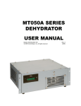
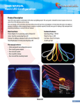
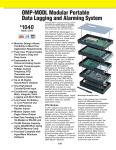
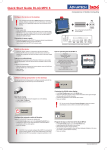
Model PFCU
S/N 9x-00nn
User's Manual
PFCU-4
Filter Set & Relay Control Unit
S/N 9x-00nn
X-ray Instrumentation Associates
1300 Mills Street
Menlo Park, CA 94025-3210
(415)-325-5779
February 15, 1991
1
Model PFCU
S/N 9x-00nn
Contents:
I: Warranty and Registration Card ........................................................... 3
A: Our guarantee policy .......................................................................
B: Our repair service............................................................................
C: Warranty Card ................................................................................
II: General Product Description.................................................................
A: Features
...................................................................................
B: Description
C: Specifications................................................................................
D: Applications...................................................................................
III: Installation
A: Unpacking
...................................................................................
B: Mechanical Installation ...................................................................
C: Electrical Connections ...................................................................
D: Initial Testing .................................................................................
IV Operation
A: Normal Operation ...........................................................................
B: Open Circuits .................................................................................
C: Short Circuits ................................................................................
V Troubleshooting and Service ................................................................
A: Detailed Theory of Operation ...........................................................
B: Service
...................................................................................
VI: Assembly Drawings and Parts List.......................................................
A: Assembly Drawings ........................................................................
B: Parts List
...................................................................................
2
Model PFCU
S/N 9x-00nn
Section I: Warranty and Registration Card
I.A. Our Guarantee Policy
PFCU control units are guaranteed against failure under normal operating conditions for 1
year from time of purchase. Should a unit fail, it will be repaired or replaced in as expeditious a
manner as possible to minimize disruption to its owner's experiments. In such an event please
call us immediately to arrange for free repair service. Be sure to register your instrument.
I.B. Our Repair Service
In line with XIA's goal of making your experimental life easier, we also have a repair
service which will attempt to repair, at a reasonable cost, any XIA instrument that fails, whether it
is in warranty or not. The components of this service, which can be selected as your needs
require, include:
1: Timely repairs: Our goal is to complete normal repairs in 2 working days or less.
2: Complete testing and checkout before return to assure that the repaired instrument will
continue to perform reliably.
3: Loaners: to keep your experiment running if we expect a delay in obtaining necessary
replacement parts.
4: Expedited handling: by 2nd day, overnight or even same day rush delivery to get you
going again in critical situations.
I.C. Warranty Card
In order to register your instrument for our guarantee policy, please fill out and return the
warranty card at the bottom of the Warranty Information sheet.
3
Model PFCU
S/N 9x-00nn
Section II: General Product Description
I.A. Features
❖ Implements both manual and computer control of PF4 filter unit, small relays or other experimental
equipment
❖ 4 output lines, each at 24V, 5 - 100 mA, diode protected for inductive loads.
❖ Outputs switched by front panel switches or TTL remote control input signals
❖ Detects both open and short circuits as error states; short circuit protected.
❖ Panel LEDs show normal activation, flash for errors states.
❖ Reports normal output activation status with TTL output signals
❖ Single width NIM module powered from the NIM bin
I.B. Description
The Model PFCU-4 is a flexible control unit both for such XIA products as the Model
PF4 Filter Inserters and Model PF2S2 Filter/Shutter Units and for many other types of small
experimental equipment. Packaged as a single width NIM module, it implements both manual
control, via front panel switches, and remote control, via TTL logic inputs and outputs. It is
thereby compatible with a variety of computer I/O modules, including both CAMAC modules
and personal computer I/O cards. Since its 4 output lines are rated for inductive loads of up to
100 mA at 24 Volts, it may also be used to control a variety of other experimental equipment
as well, either directly or through the use of relays.
The Model PFCU-4 has the following control logic for each of its 4 output lines: the
output is switched by two ORed inputs (a front panel switch and a remote, Active Lo, input
logic level). The resulting output line condition is shown by a panel LED and output as an
Active Lo TTL logic level. In this manner, if remote control is overridden from the front panel,
the actual experimental situation is still reported and can be accurately stored in the remote
controller's data record. Currents of less than 3.5 mA or greater than 110 mA are detected and
interpreted as "open" and "short" circuit conditions, respectively. As a protective feature, the
output is switched off in approximately 1 µs following detection of the short condition and must
be reset before normal operation can resume. Both short and open conditions are indicated
by flashing the faulty circuit's front panel LED and switching its output line High.
Both the TTL input and output lines are configured active Lo (0 volts = logic 1)
I.C. Technical Specifications
Physical
SIZE: Single width NIM module.
Power Required (from NIM Bin)
+12 V: 200 mA.
+24 V: up to 400 mA, depending on load.
Inputs
FRONT PANEL: 4 SPST switches "In/Out".
REMOTE INPUT: DB9 M plug, Active Lo TTL levels: 0 Volts = "1" = "In".
4
Model PFCU
S/N 9x-00nn
Controlled Output
24V, 5 - 100 mA; diode protected for inductive loads.
Connector: DB9 female receptacle.
Status Output
DB9 F receptacle; Active Lo TTL levels: 0 Volts = "1" = "valve actuated".
Fault Detection
Open Circuit: Output currents below 3.5 mA are indicated as open circuits by flashing the circuit's front
panel indicator LED and switching its status output line to "0".
Short Circuit: Output currents above 110 mA are switched off and the condition indicated by flashing the
circuit's front panel LED and switching its status output line to "0". The circuit must be reset (both inputs
turned off) before it will operate normally again.
I.D. Applications
The PFCU-4 is principally intended for controlling XIA's PF4 and PF2S2 filter and filtershutter sets. When purchased with an appropriate connector cable (see below) nothing further
is required to implement manual control. To implement computer control, only user-specific
computer-to-PFCU connection cables are required. Using this PFCU/PF4 package, it is
simple to automate data collection routines for samples whose x-ray scattering exceeds the
dynamic range of the detector by having the system control computer use the PF4 to adjust
the intensity of the x-ray beam via the PFCU interface.
With its convenient control system and protected outputs, the PFCU is also well suited
for more general experimental control. It is equally capable of driving solenoids, lamps, small
heaters, relays and various electrically operated valves. Equipment whose power
requirements exceed the PFCU's rating may still be controlled through the use of intermediate
relays.
I.E. Related Products
XIA also sells connector cables, designated PF-CAB-xx which are specifically intended
to connect the PFCU to either a PF4 or a PF2S2 unit. Available lengths xx are 15', 25' & 50'.
These are 9 conductor, 26 AWG cables configured as 4 twisted pairs plus ground inside a foil
sheath. This arrangement provides exceptional signal immunity to noise in large facility or
industrial environments.
5
Model PFCU
S/N 9x-00nn
Section III. Installation
III.A. Unpacking
When unpacking your PFCU, you should find the following 3 items:
❏ The PFCU control module.
❏ This instruction manual.
❏ A Warranty Card.
Please fill out and return the warranty card before you forget.
The following installation instructions are written assuming that the PFCU will be used to
control a PF4 filter set. For other applications, appropriate changes should be made in the
indicated procedures.
III.B. Mechanical Installation
The only mechanical installation required is to insert the PFCU into a NIM bin and tighten
the front panel thumbscrews.
III.C. Electrical Connections
III.C.1. Back Panel: Connections to Controlled Equipment
Connections between the PFCU and the controlled equipment (e.g. PF4) must be
made as shown in the following sketch, Figure 1.. Please note that the Returns are switched
and must be kept as separate leads. The common +24 Volts may be run as a single lead if
desired.
6
Model PFCU
S/N 9x-00nn
Figure 1.
Connections from PFCU to controlled equipment
PFCU Back Panel
9 Pin Female D Connector
5
4
9
3
8
2
7
1
6
Pinning Chart
Output
1
2
3
4
Common
+24 V
6
7
8
9
Switched
Return
1
2
4
5
PF4
9 Pin Male D Connector
1
2
6
3
7
4
8
5
Pinning Chart
Valve
1
2
3
4
V+
6
7
8
9
V-
1
2
4
5
9
Cables designated PF-CAB-xx obtained from XIA make these connections with the
leads for each output as a twisted pair and lead #3 as a connecting ground, as shown in the
following sketch, Figure 2.. Any cable with DB9 Male and Female connectors and straight
through connections may be used instead if it is rated to produce less than 1 Volt drop for the
intended current over twice the desired cable length.
7
Model PFCU
S/N 9x-00nn
Figure 2.
DB9 - Male
Pin #
DB9 - Female
Pin #
Cable
1
6
2
7
4
8
5
9
3
Connector Shell, if any
Connector Shell, if any
Foil Shield, if any
Foil Shield, if any
Wire Size
1
6
2
7
4
8
5
9
3
26 or 28 Gauge, nominal 0.065 ohm/ft maximum.
III.C.2. Front Panel: Connections to Computer Equipment
The required connections to appropriate computer controlled input and output registers
should be made as shown in the following sketch, Figure 3. Both inputs and outputs are Low
Power Schottky TTL and are therefore compatible with both TTL and HCMOS circuitry (Vin <
0.5 V for Low, Vin > 2.7 V for High). Both input and output are Active Low, so that nominal 0
Volts is a logic 1, and grounding an input pin (e.g. 3) will activate the associated PFCU output
channel (#2), causing the equivalent output pin (#3) also to go Low. The active low convention
was adopted to ease interfacing the PFCU to CAMAC control systems where it is common to
many input/output devices such as the Joerger QIR and QOR.
8
Model PFCU
S/N 9x-00nn
Figure 3.
PFCU Front Panel Connectors
"Status Output"
(9 Pin Female D Jack)
1
2
3
4
5
Pinning Chart
6
7
All TTL signals
Active Low: 0 Volt = Logic 1
8
9
Pin
"Control Input"
(9 Pin Male D Plug)
5
4
3
2
1
Signal/Channel
1
Ground
2
1
3
2
4
3
5
4
9
8
7
6
III.D. Initial Testing
❏
❏
❏
❏
❏
❏
III.D.1: PFCU initial manual testing
Install PFCU in NIM Bin
Power up NIM Bin
Throw each front panel switch on PFCU in turn and observe the following:
1: Associated LED on PFCU panel lights up in flashing mode.
Attach Male end of interconnector cable to rear of PFCU, F end to PF4
Throw each front panel switch on PFCU in turn and observe that the following different
things occur:
1: Associated LED on PFCU panel lights up but does not flash.
2: Corresponding PF4 valves LED lights up.
This completes initial manual testing unless you want to throw the switches a few more
times.
III.D.2: PFCU initial computer control testing
❏ Have a computer controlled TTL output register of at least 4 bits and a program to change
their values.
9
Model PFCU
S/N 9x-00nn
❏ Have a computer controlled TTL input register of at least 4 bits and a program to read
their values.
❏ With NIM bin and Computer arrays powered off:
1: Connect the PFCU "Control Input" lines to the TTL output bits.
2: Connect the PFCU "Status Output" lines to the TTL input bits.
❏ Turn the NIM bin and Computer arrays power back on.
❏ With all manual switches in OFF position, use the computer to toggle each TTL output bit
from 1 to 0 (High to Low) in turn and observe that the following things all happen:
1: Appropriate PFCU front panel LED comes on.
2: Associated PF4 valve LED comes on.
3: Associated Status bit toggles from 1 to 0 (High to Low).
❏ Also observe that when the output bits are toggled from 0 to 1 (Low to High) the
opposite things all happen:
1: Appropriate PFCU front panel LED goes off.
2: Associated PF4 valve LED goes off.
3: Associated Status bit toggles from 1 to 0.
❏ Now, with all computer output bits set to 1 (High), use the front panel switches to turn
each valve on and off in turn and confirm that the same behavior occurs as under
computer control. Namely:
1: Appropriate PFCU front panel LED turns on and off.
2: Associated PF4 valve LED turns on and off.
3: Associated Status bit toggles from 1 to 0 and back.
❏ This completes initial computer control testing.
III.A.3: Testing PF4 Pneumatic Operation
❏ This test can be performed either jointly with the tests of III.A.1 and 2 or separately.
❏ In addition to the setup required above, the PF4 must also be attached to a source of high
pressure Air or Inert Gas as per the PF4 instruction manual.
❏ The test procedures are then identical to those of Sections III.A.1 and III.A.2 above
except that an additional visual inspection is needed to confirm that, when each PF4
valve LED is lighted its corresponding pneumatic cylinder is also activated, dropping
its foil carrier (or their shafts, if the foil carriers have not yet been mounted) into the
beam path.
10
Model PFCU
S/N 9x-00nn
Section IV: Operation
IV.A. Normal Operation
The normal operation of the PFCU is quite straightforward. It consists of 4 identical
circuits, cleverly numbered 1 through 4. Each circuit is controlled by 2 inputs: a front panel
switch and a TTL control input line. Each circuit also has two output lines: a switched power
return line and a TTL status output. The correspondences between circuits and input and
output lines is shown in Figures 1 and 3. The circuit's two inputs are logically ORed together so
that when either the switch is in the "In" position or the TTL input is LO the circuit is activated.
When the circuit is activated its power return line is connected to ground through a switching
transistor and its TTL status line is switched LO. Any external device connected between the
power return line and the +24 Volts supplied is thereby also activated.
IV.B. Open Circuits
The current passing through the switching transistor is sensed and compared to 3.5 mA.
A value less than 3.5 mA when the circuit is supposed to be activated is interpreted as an
"Open" circuit and causes the circuit's front panel LED to flash as well as the output status line to
be set HIGH. As soon as the open circuit condition is removed the circuit returns to normal
operation.
IV.C. Short Circuits
The current passing through the switching transistor is also compared to a value of 110
mA. A current of greater than 110 mA is interpreted as a "Short" circuit and causes an internal
flip-flop to be set to its "Short circuit detected" position. This causes the switching transistor to
be shut off, the front panel LED to flash, and the output status line to be set HIGH.. The entire
detection and shutoff time is less than a microsecond. When the short circuit condition has been
corrected, the circuit must be reset, by switching both of its inputs OFF, before it can be turned
on again to resume normal operation. Notice that only a short circuit in the controlled circuit is
detected. Shorting the supplied +24 Volts to some external ground will not be detected by
this module
IV.D. Distinguishing Between Error Conditions
Because both error conditions are expected to be rare events, the PFCU does not
distinguish between them in its signals to the user. In both cases the front panel light flashes
and the output status line goes HIGH. The easiest way to distinguish between the two cases
(after visually checking the connections between the PFCU and the controlled device for
unplugged connectors, etc) is to measure the resistance in the external circuit which is causing
the PFCU to go into error mode. Using the 24V supply, a resistance of greater than 6800 Ω
will result in the open circuit condition. A resistance of less than 220 Ω will result in a short circuit
condition.
11
Model PFCU
S/N 9x-00nn
Section V: Troubleshooting and Service
V.A. Detailed Theory of Operation
The PFCU consists of 4 identical control circuits and 5 simple support circuits which are
common to the 4 control circuits. These latter are assynchronous oscillator circuits, a "Reset on
Power-On", a voltage divider to create 2 reference voltages for use in detecting short and open
circuit conditions, and +5 Volt voltage regulator U1.
The first oscillator (Section A of Integrated circuit U7, hereafter U7:A, etc) is a CMOS
version of a 555 oscillator/timer which uses resistors R6, R11 and capacitor C7 to produce a
square wave of about 2 MHz with about a 50% duty cycle. This signal is used as a clock for
setting and resetting the flip-flop U8 as part of short circuit detection.
The second oscillator, U7:B with R7, R13 and C6 produces about a 3 Hz signal which is
used to flash the front panel lights when error signals are detected.
The "Reset on Power-On" circuit consists of an RC network (R9, C3 & D2) with about a
1/10 sec time constant feeding two Schmidt triggers U5:A and U5:B. When VCC is first turned
on, /Reset is LO, resetting all the flip-flops in U8 to the "Not Shorted" state. After about 1/10
sec /Reset goes high, leaving the flip-flops in a well defined state.
The voltage divider consisting of R35, R40 and R43 produces the two reference
voltages Short-Ref and On-Ref used to detect the short circuit and open circuit conditions
respectively. Their design values are: Short-Ref = 0.77 Volts, On-Ref = 55 mV.
In this section we now describe the operation of a single section of the circuit, the other
three being identical in function. Closing the front panel switch S1 creates Not-Local-On-Req-1,
which is NANDed with the Active-LO signal Not-Remote-On-Req-1 by gate U2:A to produce
On-Req-1, which is HIGH when the circuit is supposed to be on. This signal is ANDed with
Not-Shorted by gate U15:A to turn on switching transistor Q1. base resistor R4 limits Q1's
base emitter current. Current flows through the external load to Q1 via inductor L1 (which is
intended to limit current surges in the case of a short circuit) and then through the sense resistor
R10. Diode D1 provides a return to +24V for inductive surges. The voltage across R10 is
compared to the On-Ref Voltage by comparator U4:B and to the Short-Ref Voltage by
comparator U4:A. The resistor networks R5-R8 and R16-R17 by positive feedback create
hysteresis for the detection of the On and Short conditions. If a short condition is detected,
Detect-Short-1 goes HIGH and is fed to flip-flop U8:1 via Or gate U6:A, causing the flip-flop
to be set to the Shorted condition on the first transition of master clock U7:A. This causes NotShorted to go LO at the input to AND gate U15:A, turning off switching transistor Q1. Although
the cessation of current through R10 then causes Detect-Short-1 to go LO, the flip-flop's own
Shorted signal is ANDed with On-Req-1 and fed back to it's input so that it remains in the
Shorted state until On-Req-1 is turned off, when it resets. The 4 state sensitive signals OnReq-1, Detect-On-1, Shorted-1, and Not-Shorted-1 are input to the logic network consisting of
U11:A, U13:A, U10:A, and U3:A to control the status of the circuit's front panel LED D4.
U11:A detects normal operating status, which it buffered to the Status Output connector J2 via
inverters U5:C and U9:A. Two inverters are used so that the final output can be LS TTL.
When a fault is detected (either Detect-On-1 or Not-Shorted-1 is LO) the output of U11:A
goes HIGH and the output of U10:A oscillates with the Flasher signal from oscillator U7:B. This
signal is ANDed by U3:A with the output of U13:A, which is HIGH when current should be
flowing, causing the LED to flash. During normal operation the output of U11:A is LO, causing
the output of U10:A to always be HIGH which, together with the HIGH output of U13:A
causes the LED to light steadily.
12
Model PFCU
S/N 9x-00nn
V.B. Service
If its warranty period has not expired we recommend that a malfunctioning unit be
returned to XIA for repair.
However, guided by the above description and using the circuit schematic and parts list
in the following section, any reasonably competent electronics technician should find the PFCU
straightforward to service in case of a component failure. By attaching a dummy load of 1200 Ω
to simulate a normal load (20 mA) and 12 KΩ to simulate an open circuit (2 mA), the various
logic levels are readily verified. Testing the short circuit protection is more complex since Q1
normally remains on for less than 1 µs. In this case attach a load of 160 Ω or less to the output
and connect a 0-5 V square wave pulser at a frequency of between 1 and 10 kHz to the
appropriate Control Input connecter pin. This will cause the unit to be turned on and reset at the
pulser frequency so the transient behavior can be examined using an oscilloscope triggered
by the pulser. A time base of about 1 µs/div will be appropriate. In particular, the comparator
U4:A should start triggering when Ve at the emitter of Q1 passes 0.77 Volts. However, due to
propagation and clock cycle delays, Ve may rise as high as 1.9 Volts and saturate briefly (for a
true short circuit) before Q1 is switched off.
Section VI: Circuit Schematic and Parts List
VI.A. Circuit Schematic:
The circuit schematic follows this page.
VI.B. Parts List:
The parts list follows the circuit schematic.
13