1
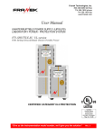
CPE Tower Battery Pack
User’s Manual
Para Systems, Inc.
1455 LeMay Dr.
Carrollton, TX 75007
Phone: 1-972-446-7363
Fax: 1-972-446-9011
Internet: minutemanups.com
UPS Sizing: sizemyups.com
PN - 34000279
Table of Contents
Important Safety Instructions .................................................................2
1. Introduction ..........................................................................................4
2. Introduction to the Rear Panel ...........................................................4
3. Installation ............................................................................................5
3.1. Unpacking .......................................................................................5
3.2. Selecting Installation Position .........................................................6
3.3. Installing the Battery Pack...............................................................7
3.4. Storage Instructions ........................................................................8
4. Maintenance Guide ..............................................................................8
4.1. Maintenance....................................................................................8
4.2. Replacing the Batteries ...................................................................9
4.3. Battery Replacement Procedure .....................................................10
Appendix...................................................................................................14
A.1. Specifications..................................................................................14
A.2. Obtaining Service............................................................................15
A.3. Limited Warranty.............................................................................16
© Copyright Para Systems, Inc., 2006
1
IMPORTANT SAFETY INSTRUCTIONS
This manual contains important instructions that should be followed during
the installation and the maintenance of the Battery Pack.
SAVE THESE INSTRUCTIONS
An Important Notice
•
•
•
•
•
•
•
•
•
•
•
•
•
•
•
•
•
To ensure safety in all applications ensure that a Qualified Service
Personnel installs the system.
Do not open the unit there are no serviceable parts inside. This will
void the warranty.
Do not try to repair the unit yourself, see Obtaining Service.
To eliminate any overheating of the Battery Pack, keep all ventilation
openings free from obstruction, and do not store anything on top of the
Battery Pack. Keep the Battery Pack 8-inches away from the wall.
Make sure the Battery Pack is installed in the proper environment as
specified. (0-40°C and 30-90% non-condensing humidity)
Do not install the Battery Pack in direct sunlight.
Install the Battery Pack indoors as it is not designed for outdoor use.
Dusty, corrosive and salty environments will damage the Battery Pack.
Install the Battery Pack away from; objects which give off excessive
heat and areas, which are excessively wet.
The battery will discharge naturally if the system is unused for prolonged
periods of time.
It is recommended that the batteries be recharged every 2-3 months
while the Battery Pack is not in service.
This Battery Pack is intended for use in a Controlled Environment.
Servicing of Batteries should be performed by Qualified Service
Personnel Only.
When Replacing Batteries, Replace With the Same Number and Type.
CAUTION – Do Not dispose of the battery in a fire. The battery may
explode.
CAUTION – Do not open or mutilate the battery. Released electrolyte
is harmful to the skin and eyes. It may be toxic.
CAUTION – Risk of Electric Shock – The battery circuit is not isolated
from AC, hazardous Voltage may exist between battery terminals and
ground. Test before touching.
2
•
CAUTION – A Battery can present a Risk of Electrical Shock and High
Short-Circuit Current. The following precaution should be observed
when working with the batteries:
A. Remove watches, rings, or other metal objects.
B. Use tools with insulated handles.
C. Wear rubber gloves and boots.
D. Wear protective eye gear (goggles).
E. Do not lay tools or metal parts on top of batteries.
F. Disconnect charging source prior to connecting or disconnecting
battery terminals.
Receiving Inspection
After removing your MINUTEMAN Battery Pack from its carton, it should be
inspected for damage that may have occurred in shipping. Immediately
notify the carrier and place of purchase if any damage is found. Warranty
claims for damage caused by the carrier will not be honored. The packing
materials that your Battery Pack was shipped in are carefully designed to
minimize any shipping damage. In the unlikely case that the Battery Pack
needs to be returned to MINUTEMAN, please use the original packing
material. Since MINUTEMAN is not responsible for shipping damage
incurred when the system is returned, the original packing material is
inexpensive insurance. PLEASE SAVE THE PACKING MATERIALS!
Para Systems Life Support Policy
As a general policy, Para Systems Inc. (Para Systems) does not
recommend the use of any of its products in life support applications where
failure or malfunction of the Para Systems product can be reasonably
expected to cause failure of the life support device or to significantly affect
its safety or effectiveness. Para Systems does not recommend the use of
any of its products in direct patient care. Para Systems will not knowingly
sell its products for use in such applications unless it receives in writing
assurances satisfactory to Para Systems that (a) the risks of injury or
damage have been minimized, (b) the customer assumes all such risks,
and (c) the liability of Para Systems Inc. is adequately protected under the
circumstances.
3
Chapter One:
Introduction
1. Battery Over-current Protection
2. DC bus voltage disconnect device
External battery connector for the 2nd(or
2. EXT.BAT. +/next) Battery Pack connected
External battery connector for the UPS
3. UPS BAT. +/The inlet for the internal charger the Battery
4. Charger Inlet
Pack (Optional)
On/Off switch to control the internal charger
5. Charger Switch (Optional)
To show that the internal charger is
6. Utility Indicator connected to Utility and is charging the
batteries (Optional)
1. DC Breaker
Thank you for purchasing a MINUTEMAN power protection product. It has
been designed and manufactured to provide many years of trouble free
service.
Please read this manual before installing your CPE Battery Pack Series,
models CPEBP1000, CPEBP2000, CPEBP3000, as it provides important
information that should be followed during installation and maintenance of
the Battery Pack and batteries allowing you to correctly set up your system
for the maximum safety and performance. Included is information on
customer support and factory service if it is required. If you experience a
problem with the Battery Pack please refer to the Obtaining Service section
in this manual to collect enough information so that the MINUTEMAN
Technical Support Department can rapidly assist you.
Chapter Two: Introduction to the Rear Panel
Chapter Three: Installation
The packing condition and the external outlook of the unit should be
inspected carefully before installation. Retain the packing material for
future use.
3.1. Unpacking
1.
2.
3
2
1
Take the Battery Pack out of the box.
Remove the packing material.
These Battery Packs are extremely heavy.
Use the
NOTE:
appropriate number of personnel when unpacking and lifting the unit.
Standard Package includes:
a. Battery Pack
b. User's Manual
c. External Battery Cable (Anderson connector to Anderson connector)
d. External battery cable strain relief
RED
2、3
6
5
4
BLACK
External Battery Cable (1-piece)
External battery cable strain relief (2-pieces)
4
5
3.2. Selecting Installation Position
3.3. Installing the Battery Pack
The CPE Battery Pack Series is intended to be install in a temperature
controlled environment that is free of conductive contaminants. Select a
location, which will provide good air circulation for the Battery Pack. Avoid
locations near heating devices, water or excessive humidity, or where the
Battery Pack is exposed to direct sunlight.
Be sure to read all of the WARNINGS and the CAUTIONS before installing the
Battery Pack. Place the Battery Pack in the final desired location and complete
the rest of the installation procedure. USE CAUTION: The Battery Pack is
heavy. Use the appropriate number of personnel when installing the Battery
Pack. The installation should be conducted or supervised by a Qualified
Service Personnel. It is recommended that the Battery Pack batteries be
charged for a minimum of 4-hours before use. The Battery Pack may be used
immediately, however, the “On-Battery” runtime may be less than normally
expected.
Operating Temperature (Max): 0 to 40 degrees C (+32 to +104 degrees F)
Operating Elevation: 0 to 3,000m (0 to +10,000 ft)
Operating and Storage Relative Humidity: 30 - 90%, non-condensing
Storage Temperature: -15 to +45 degrees C (+5 to +113 degrees F)
Storage Elevation: 0 to 15,000m (0 to +50,000 ft)
1.
2.
3.
4.
Keep at least 20cm (8-inches) clearance from the rear panel of the UPS
to the wall.
Do not block the airflow to the ventilation openings of the unit.
These Battery Packs are intended for a Controlled Environment.
Do not place the Battery Pack in an environment near dusty, corrosive
or flammable materials.
1
ON
OFF
2
3
4
OFF
ON
Install the Battery Pack in its final location next to the UPS. The UPS must be in
the off position.
1. All of the DC Breakers on the rear panel of all of the Battery Packs must be
in the off position.
2. Install the External battery cable strain relief on each end of all of the
External battery cables.
3. Remove the retaining screws from the external battery connector cover
plates on the rear panel of the UPS and the Battery Pack. Connect the
External battery cable to the external battery connector on the rear panel of
the UPS (verify polarity, Red to Red and Black to Black). Secure the
External battery cable to the rear panel of the UPS with the retaining screw.
Connect the other end of the External battery cable to the external battery
connector on the rear panel of the Battery Pack (verify polarity, Red to Red
and Black to Black). Secure the External battery cable to the rear panel of
the Battery Pack with the retaining screw.
4. Once all of the External battery cables are connected turn on all of the DC
Breakers on the rear panel of all of the Battery Packs.
5. The Battery Pack installation is complete. See the UPS User’s Manual for
connecting the equipment and the start-up of the UPS system.
6
7
Daisy Chaining Configuration
4.2. Replacing the Batteries
(QUALIFIED SERVICE PERSONNEL ONLY)
The CPE Tower Battery Pack has an easy to replace hot-swappable
batteries. Please read all of the WARNINGS and CAUTIONS before
attempting to service the batteries.
NOTE: If there is a power interruption while replacing the hot-swappable
batteries, with the UPS on, the “On-Battery” runtime may be less than
normally expected.
•
Second Battery Pack
First Battery Pack
UPS
USE CAUTION: These Battery Packs are extremely heavy.
• WARNING – This Battery Pack contains potentially hazardous voltages.
Do not attempt to disassemble the Battery Pack beyond the battery
replacement procedure. This Battery Pack contains no user serviceable
parts. The repairs and the Battery replacement must be performed by
QUALIFIED SERVICE PERSONNEL ONLY.
• CAUTION – Do not open or mutilate batteries.
harmful to the skin and eyes and may be toxic.
3.4. Storage Instruction
For extended storage through moderate climate, the batteries should be
charged for 24-hours every 3-months. Repeat this every 2-months under
high temperature environment.
Chapter Four: Maintenance Guide
4.1. Maintenance
Clean the dust from the ventilation openings and intakes on the rear panel.
1. Turn off the Battery Pack and wipe the case with a damp cloth.
2. Periodically unplug the input power cord of the UPS from the wall outlet
to test the batteries.
3. Save all open applications before performing the battery test.
8
Released electrolyte is
• CAUTION – Do not dispose of batteries in a fire. The batteries may
explode. The batteries in these Battery Packs are recyclable. Dispose of
the batteries properly. The batteries contain lead and pose a hazard to the
environment and human health if not disposed of properly. Refer to local
codes for proper disposal requirements or return the battery to MINUTEMAN.
• CAUTION – Although battery system voltages are 36VDC, 72VDC and
96VDC the battery system can still present a risk of electrical shock. These
batteries produce sufficient current to burn wire or tools very rapidly,
producing molten metal. Observe these precautions when replacing the
batteries:
1. Remove watches, rings, or other metal objects.
2. Use hand tools with insulated handles.
3. Wear protective eye gear (goggles).
4. Wear rubber gloves and boots.
5. Do not lay tools or other metal parts on top of batteries.
6. Disconnect the charging source prior to connecting or disconnecting the
battery terminals.
7. Determine if the battery is inadvertently grounded. If the battery is,
remove the source of the grounding. Contact with any part of a
grounded battery can result in an electrical shock. The likelihood of
such shock will be reduced, if such grounds are removed during
installation and maintenance.
9
• CAUTION – Replace batteries with the same number and type as
originally installed in the Battery Pack. These batteries have pressureoperated vents. These Battery Packs contain sealed non-spillable lead
acid batteries.
Model Number
CPEBP1000
CPEBP2000
CPEBP3000
Battery
9-12V7Ah
18-12V7Ah
16-12V7Ah
QTY/Rating
CSB
GP1270 F2
GP1270 F2
GP1270 F2
Part Number
Panasonic
LC-R127R2CH1 LC-R127R2CH1 LC-R127R2CH1
Part Number
Yuasa
NP7-12
NP7-12
NP7-12
Part Number
4.3. Battery Replacement Procedure
PLEASE READ THE CAUTIONS AND
ATTEMPTING TO REPLACE THE BATTERIES
•
WARNINGS
BEFORE
CAUTION - DO NOT short-circuit any of the battery wires to the chassis
or to any component.
NOTE:
Do not pinch the battery wires with the battery-retaining brackets.
NOTE: It is recommended that you draw a diagram of battery position and
the battery connections before disconnecting any of the battery wires.
Hot-swappable batteries mean that the batteries can be replaced without
powering down the whole UPS system.
NOTE: If there is a power interruption while replacing the hot-swappable
batteries, with the UPS on, the “On-Battery” runtime may be less than
normally expected. To hot-swap the batteries start with step 6.
10. Disconnect the battery positive (red) wires.
NOTE: Use CAUTION, do not touch the battery positive (red) wire to the
battery negative (black) wire or the chassis.
11. Disconnect the battery negative (black) wires.
12. Remove the battery-retaining bracket retaining screws.
13. Remove the battery-retaining brackets.
14. Disconnect the battery jumper wires.
15. Remove the old batteries.
16. Install the new batteries.
17. Reconnect the battery jumper wires.
18. Re-install the battery-retaining bracket (s).
19. Re-install the battery-retaining bracket retaining screws.
20. Reconnect the battery negative (black) wires to the battery negative
terminals. Verify proper polarity.
21. Reconnect the battery positive (red) wires to the battery positive
terminals. Verify proper polarity.
22. Re-install the cover.
23. Re-install the cover screws.
24. Once all of the batteries have been replaced in all of the Battery Packs
reconnect ALL of the External battery cables to the rear panel of the
UPS and ALL of the Battery Packs.
25. Turn on ALL of the DC Breakers on the rear panel of the Battery Packs.
26. Reconnect the computer interface cable to the rear panel of the UPS.
27. Plug the equipment into the output receptacles of the UPS.
28. Plug the UPS's Input power cord into the wall outlet.
29. Press the On/Off switch on the front panel to turn the UPS ON.
30. Turn on the equipment.
31. The UPS is now ready for normal operation.
32. Dispose of the old batteries properly at an appropriate recycling facility
or return them to the supplier in the packing material for the new
batteries.
1. Turn off the equipment that is plugged into the output receptacles of the
UPS.
2. Press the On/Off switch on the front panel to turn the UPS OFF.
3. Unplug the UPS's Input power cord from the wall outlet.
4. Unplug the equipment from the output receptacles of the UPS.
5. Unplug the computer interface cable from the rear panel of the UPS.
6. Turn ALL of the DC Breakers on the rear panel of ALL of the Battery
Packs off.
7. Disconnect ALL of the External battery cables from the rear panel of the
UPS and ALL of the Battery Packs.
8. Remove the cover screws.
9. Remove the cover.
10
11
CPEBP1000
CPEBP2000, CPEBP3000
1
1
DC BREAKER
DC BREAKER
UPS BAT.
UPS BAT.
EXT. BAT.
EXT. BAT.
CHARGER SW.
CHARGER SW.
AC INPUT
CHARGER POWER
AC INPUT
CHARGER POWER
2
2
3
3
12
13
Appendix
A.2. Obtaining Service
A.1. Specifications
If the Battery Pack requires Service:
MODEL
CPEBP1000
CPEBP2000
CPEBP3000
PHYSICAL
Dimensions Net
(WxHxD)
Weight Net
7.1x15.2x15.9 inch
(180x385x403 mm)
7.1x15.2x24.0 inch
(180x385x609 mm)
7.1x15.2x24.0 inch
(180x385x609 mm)
72.75 Lbs
33 Kgs
121.25 Lbs
55 Kgs
110.20 Lbs
50 Kgs
Dimensions
Shipping
12.7x20.6x21.6 inch
(322x524x549 mm)
12.7x20.6x29.9 inch
(322x524x760 mm)
12.7x20.6x29.9 inch
(322x524x760 mm)
78 Lbs
35 Kgs
126 Lbs
57 Kgs
115 Lbs
52 Kgs
(WxHxD)
Weight Shipping
ENVIRONMENT
Operating Temp
0 to 40°C (+32 to +104°F)
Storage Temp
-15 to +45°C (+5 to +113°F)
Operating/Storag
30 to 90% Non-Condensing
e Humidity
Operating
0 to 3,000m (0 to +10,000 ft)
Elevation
Storage
0 to 15,000m (0 to +50,000 ft)
Elevation
SAFETY CONFORMANCE
Safety Standard
UL1778, CSA 22.2 (cUL)
BATTERY
Type
Sealed, Non-Spillable, Maintenance Free,
Valve Regulated, Lead Acid
Quantity/Rating
9-12V7Ah
18-12V7Ah
16-12V7Ah
System Voltage
36VDC
72VDC
96VDC
System Amp-hour
21.0
21.0
14.0
Recharge Time
8 Hours to 90% from total discharge
Typical Battery 3-5 years, depending on number of discharge cycles
Life
and ambient temperature
14
1.Use the UPS TROUBLESHOOTING section to eliminate obvious causes.
2.Verify there are no circuit breakers tripped. A tripped circuit breaker is
the most common problem.
3.Call your dealer for assistance. If you cannot reach your dealer, or if they
cannot resolve the problem call or fax MINUTEMAN Technical Support at
the following numbers; Voice phone (972) 446-7363, FAX line (972) 4469011 or visit our Web site at www.minutemanups.com the "Discussion
Board". Please have the following information available BEFORE calling
the Technical Support Department.
A. Your name and address.
B. Where and when the unit was purchased.
C. All of the model information about your Battery Pack and UPS.
D. Any information on the failure, including LEDs that may be illuminated.
E. A description of the protected equipment, including model numbers if
possible.
F. A technician will ask you for the above information and, if possible, help
solve your problem over the phone. In the event that the unit requires
factory service, the technician will issue you a Return Material Authorization
Number (RMA #).
G. If the Battery Pack is under warranty, the repairs will be done at no
charge. If not, there will be a charge for repair.
4. Pack the Battery Pack in its original packaging. If the original packaging
is no longer available, ask the Technical Support Technician about obtaining
a new set. It is important to pack the Battery Pack properly in order to
avoid damage in transit. Never use Styrofoam beads for a packing material.
A. Include a letter with your name, address, daytime phone number, RMA
number, a copy of your original sales receipt, and a brief description of the
problem.
5. Mark the RMA # on the outside of all packages. The factory cannot
accept any package without the RMA # marked on the outside.
6. Return the Battery Pack by insured, prepaid carrier to:
Para Systems Inc.
MINUTEMAN UPS
1455 LeMay Drive
Carrollton, TX 75007
ATTN: RMA # _______
15
A.3. Limited Product Warranty
Para Systems Inc. (Para Systems) warrants this equipment, when properly applied
and operated within specified conditions, against faulty materials or workmanship for
a period of three years from the date of purchase. For equipment sites within the
United States and Canada, this warranty covers repair or replacement of defective
equipment at the discretion of Para Systems. Repair will be from the nearest
authorized service center. Replacement parts and warranty labor will be borne by
Para Systems. For equipment located outside of the United States and Canada,
Para Systems only covers faulty parts. Para Systems products repaired or replaced
pursuant to this warranty shall be warranted for the un-expired portion of the warranty
applying to the original product. This warranty applies only to the original purchaser
who must have properly registered the product within 10 days of purchase.
The warranty shall be void if (a) the equipment is damaged by the customer, is
improperly used, is subjected to an adverse operating environment, or is operated
outside the limits of its electrical specifications; (b) the equipment is repaired or
modified by anyone other than Para Systems or Para Systems approved personnel;
or (c) has been used in a manner contrary to the product’s User's Manual or other
written instructions.
Any technical advice furnished before or after delivery in regard to use or application
of Para Systems’s equipment is furnished without charge and on the basis that it
represents Para Systems’s best judgment under the circumstances, but it is used at
the recipient’s sole risk.
EXCEPT AS PROVIDED HEREIN, PARA SYSTEMS MAKES NO WARRANTIES,
EXPRESSED OR IMPLIED, INCLUDING WARRANTIES OF MERCHANTABILITY
AND FITNESS FOR A PARTICULAR PURPOSE. Some states do not permit
limitation of implied warranties; therefore, the aforesaid limitation(s) may not apply to
the purchaser.
EXCEPT AS PROVIDED ABOVE, IN NO EVENT WILL PARA SYSTEMS BE
LIABLE FOR DIRECT, INDIRECT, SPECIAL, INCIDENTAL, OR CONSEQUENTIAL
DAMAGES ARISING OUT OF THE USE OF THIS PRODUCT, EVEN IF ADVISED
OF THE POSSIBILITY OF SUCH DAMAGE. Specifically, Para Systems is not liable
for any costs, such as lost profits or revenue, loss of equipment, loss of use of
equipment, loss of software, loss of data, cost of substitutes, claims by third parties,
or otherwise. The sole and exclusive remedy for breach of any warranty, expressed
or implied, concerning Para Systems’s products and the only obligation of Para
Systems hereunder, shall be the repair or replacement of defective equipment,
components, or parts; or, at Para Systems’s option, refund of the purchase price or
substitution with an equivalent replacement product. This warranty gives you
specific legal rights and you may also have other rights, which vary from state to
state.
Longer term and F.O.B. job site warranties are available at extra cost. Contact Para
Systems (1-972-446-7363) for details.
16