1
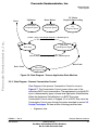
Freescale Semiconductor, Inc...
Freescale Semiconductor, Inc.
3-Phase Sensorless
BLDC Motor Control
with Back-EMF
Zero Crossing
Detection Using
56F805
56800
Designer Reference
Manual
Hybrid Controller
DRM027/D
Rev. 0, 03/2003
MOTOROLA.COM/SEMICONDUCTORS
For More Information On This Product,
Go to: www.freescale.com
Freescale Semiconductor, Inc...
Freescale Semiconductor, Inc.
For More Information On This Product,
Go to: www.freescale.com
Freescale Semiconductor, Inc.
Freescale Semiconductor, Inc...
3-Phase Sensorless BLDC
Motor Control with BEMF
Zero Crossing Using 56F805
Designer Reference Manual — Rev 0
by: Libor Prokop
Motorola Czech System Laboratories
Roznov pod Radhostem, Czech Republic
DRM027 — Rev 0
Designer Reference Manual
MOTOROLA
3
For More Information On This Product,
Go to: www.freescale.com
Freescale Semiconductor, Inc.
Revision history
To provide the most up-to-date information, the revision of our
documents on the World Wide Web will be the most current. Your printed
copy may be an earlier revision. To verify you have the latest information
available, refer to:
http://www.motorola.com/semiconductors
Freescale Semiconductor, Inc...
The following revision history table summarizes changes contained in
this document. For your convenience, the page number designators
have been linked to the appropriate location.
Revision history
Date
Revision
Level
February,
2003
1
Description
Initial release
Designer Reference Manual
Page
Number(s)
N/A
DRM027 — Rev 0
4
MOTOROLA
For More Information On This Product,
Go to: www.freescale.com
Freescale Semiconductor, Inc.
Designer Reference Manual — 3-ph BLDC with Sensorless ZC Detection
List of Sections
Section 1. Introduction . . . . . . . . . . . . . . . . . . . . . . . . . . . 15
Freescale Semiconductor, Inc...
Section 2. System Description. . . . . . . . . . . . . . . . . . . . . 17
Section 3. BLDC Motor Control . . . . . . . . . . . . . . . . . . . . 23
Section 4. Hardware Design. . . . . . . . . . . . . . . . . . . . . . . 59
Section 5. Software Design . . . . . . . . . . . . . . . . . . . . . . . 81
Section 6. Software Algorithms . . . . . . . . . . . . . . . . . . . 101
Section 7. Customization Guide . . . . . . . . . . . . . . . . . . 155
Section 8. Application Setup . . . . . . . . . . . . . . . . . . . . . 167
Appendix A. References. . . . . . . . . . . . . . . . . . . . . . . . . 183
Appendix B. Glossary. . . . . . . . . . . . . . . . . . . . . . . . . . . 185
DRM027 — Rev 0
Designer Reference Manual
MOTOROLA
5
For More Information On This Product,
Go to: www.freescale.com
Freescale Semiconductor, Inc.
Freescale Semiconductor, Inc...
List of Sections
Designer Reference Manual
DRM027 — Rev 0
6
MOTOROLA
For More Information On This Product,
Go to: www.freescale.com
Freescale Semiconductor, Inc.
Designer Reference Manual — 3-ph BLDC with Sensorless ZC Detection
Table of Contents
Freescale Semiconductor, Inc...
Section 1. Introduction
1.1
Contents . . . . . . . . . . . . . . . . . . . . . . . . . . . . . . . . . . . . . . . . . .15
1.2
Application Functionality . . . . . . . . . . . . . . . . . . . . . . . . . . . . . . 15
1.3
Benefits of the Solution. . . . . . . . . . . . . . . . . . . . . . . . . . . . . . . 15
Section 2. System Description
2.1
Contents . . . . . . . . . . . . . . . . . . . . . . . . . . . . . . . . . . . . . . . . . .17
2.2
System Specification . . . . . . . . . . . . . . . . . . . . . . . . . . . . . . . . 17
2.3
System Concept . . . . . . . . . . . . . . . . . . . . . . . . . . . . . . . . . . . . 20
Section 3. BLDC Motor Control
3.1
Contents . . . . . . . . . . . . . . . . . . . . . . . . . . . . . . . . . . . . . . . . . .23
3.2
Brushless DC Motor Control Theory. . . . . . . . . . . . . . . . . . . . .23
3.3
Control Technique . . . . . . . . . . . . . . . . . . . . . . . . . . . . . . . . . . 40
Section 4. Hardware Design
4.1
Contents . . . . . . . . . . . . . . . . . . . . . . . . . . . . . . . . . . . . . . . . . .59
4.2
System Configuration and Documentation . . . . . . . . . . . . . . . . 59
4.3
All HW Sets Components . . . . . . . . . . . . . . . . . . . . . . . . . . . . . 68
4.4
Low-Voltage Evaluation Motor Hardware Set Components . . . 70
4.5
Low-Voltage Hardware Set Components . . . . . . . . . . . . . . . . . 72
4.6
High-Voltage Hardware Set Components. . . . . . . . . . . . . . . . . 75
DRM027 — Rev 0
Designer Reference Manual
MOTOROLA
7
For More Information On This Product,
Go to: www.freescale.com
Freescale Semiconductor, Inc.
Table of Contents
Freescale Semiconductor, Inc...
Section 5. Software Design
5.1
Contents . . . . . . . . . . . . . . . . . . . . . . . . . . . . . . . . . . . . . . . . . .81
5.2
Introduction . . . . . . . . . . . . . . . . . . . . . . . . . . . . . . . . . . . . . . . . 81
5.3
Main SW Flow Chart. . . . . . . . . . . . . . . . . . . . . . . . . . . . . . . . . 81
5.4
Data Flow . . . . . . . . . . . . . . . . . . . . . . . . . . . . . . . . . . . . . . . . . 84
5.5
State Diagram. . . . . . . . . . . . . . . . . . . . . . . . . . . . . . . . . . . . . . 89
Section 6. Software Algorithms
6.1
Contents . . . . . . . . . . . . . . . . . . . . . . . . . . . . . . . . . . . . . . . . .101
6.2
Introduction . . . . . . . . . . . . . . . . . . . . . . . . . . . . . . . . . . . . . . . 101
6.3
BLDC Motor Commutation with Zero Crossing Sensing. . . . . 101
Section 7. Customization Guide
7.1
Contents . . . . . . . . . . . . . . . . . . . . . . . . . . . . . . . . . . . . . . . . .155
7.2
Application Suitability Guide . . . . . . . . . . . . . . . . . . . . . . . . . . 155
7.3
Setting of SW Parameters for Customer Motor . . . . . . . . . . . 157
Section 8. Application Setup
8.1
Contents . . . . . . . . . . . . . . . . . . . . . . . . . . . . . . . . . . . . . . . . .167
8.2
Introduction . . . . . . . . . . . . . . . . . . . . . . . . . . . . . . . . . . . . . . . 167
8.3
Warning . . . . . . . . . . . . . . . . . . . . . . . . . . . . . . . . . . . . . . . . . 167
8.4
Application Outline . . . . . . . . . . . . . . . . . . . . . . . . . . . . . . . . . 168
8.5
Application Description . . . . . . . . . . . . . . . . . . . . . . . . . . . . . . 169
8.6
Application Set-Up . . . . . . . . . . . . . . . . . . . . . . . . . . . . . . . . . 173
8.7
Projects Files . . . . . . . . . . . . . . . . . . . . . . . . . . . . . . . . . . . . .178
8.8
Application Build & Execute . . . . . . . . . . . . . . . . . . . . . . . . . . 180
Appendix A. References
Designer Reference Manual
DRM027 — Rev 0
8
MOTOROLA
For More Information On This Product,
Go to: www.freescale.com
Freescale Semiconductor, Inc.
Freescale Semiconductor, Inc...
Appendix B. Glossary
DRM027 — Rev 0
Designer Reference Manual
MOTOROLA
9
For More Information On This Product,
Go to: www.freescale.com
Freescale Semiconductor, Inc.
Freescale Semiconductor, Inc...
Table of Contents
Designer Reference Manual
DRM027 — Rev 0
10
MOTOROLA
For More Information On This Product,
Go to: www.freescale.com
Freescale Semiconductor, Inc.
Designer Reference Manual — 3-ph BLDC with Sensorless ZC Detection
List of Figures
Figure
Freescale Semiconductor, Inc...
2-1
3-1
3-2
3-3
3-4
3-5
3-6
3-7
3-8
3-9
3-10
3-11
3-12
3-13
3-14
3-15
3-16
3-17
3-18
3-19
3-20
3-21
3-22
3-23
3-24
4-1
Title
Page
System Concept . . . . . . . . . . . . . . . . . . . . . . . . . . . . . . . . . . . . 21
BLDC Motor - Cross Section . . . . . . . . . . . . . . . . . . . . . . . . . . 24
Three Phase Voltage System . . . . . . . . . . . . . . . . . . . . . . . . . . 25
BLDC Motor - Back EMF and Magnetic Flux . . . . . . . . . . . . . . 26
Classical System . . . . . . . . . . . . . . . . . . . . . . . . . . . . . . . . . . . 27
Power Stage - Motor Topology . . . . . . . . . . . . . . . . . . . . . . . . . 28
Phase Voltage Waveforms . . . . . . . . . . . . . . . . . . . . . . . . . . . .32
Mutual Inductance Effect . . . . . . . . . . . . . . . . . . . . . . . . . . . . . 32
Detail of Mutual Inductance Effect . . . . . . . . . . . . . . . . . . . . . . 34
Mutual Capacitance Model . . . . . . . . . . . . . . . . . . . . . . . . . . . .35
Distributed Back-EMF by Unbalanced Capacity Coupling . . . . 36
Balanced Capacity Coupling. . . . . . . . . . . . . . . . . . . . . . . . . . . 37
Back-EMF Sensing Circuit Diagram . . . . . . . . . . . . . . . . . . . . .38
The Zero Crossing Detection . . . . . . . . . . . . . . . . . . . . . . . . . . 39
PWM with BLDC Power Stage . . . . . . . . . . . . . . . . . . . . . . . . . 41
3-phase BLDC Motor Commutation PWM Signal. . . . . . . . . . . 42
BLDC Commutation with Bipolar (Hard) Switching. . . . . . . . . . 43
BEMF Zero Crossing Synchronization with PWM . . . . . . . . . . 44
Commutation Control Stages . . . . . . . . . . . . . . . . . . . . . . . . . . 46
Alignment . . . . . . . . . . . . . . . . . . . . . . . . . . . . . . . . . . . . . . . . . 48
Flow Chart - BLDC Commutation
with BEMF Zero Crossing Sensing. . . . . . . . . . . . . . . . . . . . . . 50
BLDC Commutation Times with Zero Crossing sensing. . . . . . 51
Vectors of Magnetic Fields . . . . . . . . . . . . . . . . . . . . . . . . . . . .55
Back-EMF at Start-Up. . . . . . . . . . . . . . . . . . . . . . . . . . . . . . . . 56
Calculation of the Commutation Times during the Starting
(Back-EMF Acquisition) Stage . . . . . . . . . . . . . . . . . . . . . . . . . 57
Low-Voltage Evaluation Motor Hardware
System Configuration . . . . . . . . . . . . . . . . . . . . . . . . . . . . . . . . 62
DRM027 — Rev 0
Designer Reference Manual
MOTOROLA
11
For More Information On This Product,
Go to: www.freescale.com
Freescale Semiconductor, Inc.
List of Figures
Freescale Semiconductor, Inc...
4-2
4-3
4-4
4-5
4-6
5-1
5-2
5-3
5-4
5-5
5-6
5-7
5-8
5-9
5-10
6-1
8-1
8-2
8-3
8-4
8-5
8-6
8-7
8-8
8-9
Low-Voltage Hardware System Configuration . . . . . . . . . . . . . 64
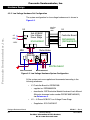
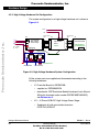
High-Voltage Hardware System Configuration . . . . . . . . . . . . . 66
Block Diagram of the DSP56F805EVM . . . . . . . . . . . . . . . . . . 69
Block Diagram . . . . . . . . . . . . . . . . . . . . . . . . . . . . . . . . . . . . . 73
3-Phase AC High Voltage Power Stage . . . . . . . . . . . . . . . . . . 76
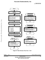
Main Software Flow Chart - Part 1 . . . . . . . . . . . . . . . . . . . . . . 83
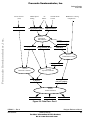
Main Software Flow Chart - Part 2 . . . . . . . . . . . . . . . . . . . . . . 84
Data Flow - Part 1. . . . . . . . . . . . . . . . . . . . . . . . . . . . . . . . . . .85
Data Flow - Part 2. . . . . . . . . . . . . . . . . . . . . . . . . . . . . . . . . . .86
Closed Loop Control System . . . . . . . . . . . . . . . . . . . . . . . . . . 87
State Diagram - Process Application State Machine . . . . . . . . 91
State Diagram - Process Commutation Control . . . . . . . . . . . . 93
Substates - Running . . . . . . . . . . . . . . . . . . . . . . . . . . . . . . . . . 94
State Diagram - Process Speed PI Controller . . . . . . . . . . . . . 97
State Diagram - Process Speed PI Controller . . . . . . . . . . . . . 98
bldczc_sTimes Structure Members and BLDC Commutation
with Zero Crossing Sensing . . . . . . . . . . . . . . . . . . . . . . . . . . 112
RUN/STOP Switch and UP/DOWN Buttons
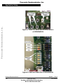
at DSP56F805EVM . . . . . . . . . . . . . . . . . . . . . . . . . . . . . . . . 170
USER and PWM LEDs at DSP56F805EVM. . . . . . . . . . . . . . 170
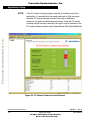
PC Master Software Control Window . . . . . . . . . . . . . . . . . . . 172
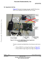
Set-up of the BLDC Motor Control Application
using DSP56F805EVM. . . . . . . . . . . . . . . . . . . . . . . . . . . . . . 173
Set-up of the Low-Voltage BLDC Motor Control Application . 174
Set-up of the High-Voltage BLDC Motor Control Application . 175
DSP56F805EVM Jumper Reference . . . . . . . . . . . . . . . . . . . 177
Target Build Selection. . . . . . . . . . . . . . . . . . . . . . . . . . . . . . . 180
Execute Make Command . . . . . . . . . . . . . . . . . . . . . . . . . . . . 181
Designer Reference Manual
DRM027 — Rev 0
12
MOTOROLA
For More Information On This Product,
Go to: www.freescale.com
Freescale Semiconductor, Inc.
Designer Reference Manual — 3-ph BLDC with Sensorless ZC Detection
List of Tables
Table
Freescale Semiconductor, Inc...
2-1
2-2
2-3
4-1
4-2
4-3
4-4
4-5
6-1
6-2
6-3
6-4
6-5
6-6
6-7
6-8
6-9
6-10
6-11
6-12
6-13
6-14
6-15
6-16
6-17
6-18
6-19
6-20
Title
Page
Low Voltage Evaluation Hardware Set Specifications . . . . . . . 18
Low Voltage Hardware Set Specifications . . . . . . . . . . . . . . . . 19
High Voltage Evaluation Hardware Set Specifications . . . . . . . 20
Electrical Characteristics of the EVM Motor Board. . . . . . . . . . 71
Characteristics of the BLDC motor . . . . . . . . . . . . . . . . . . . . . . 71
Electrical Chatacteristics of the 3-Ph BLDC
Low Voltage Power Stage . . . . . . . . . . . . . . . . . . . . . . . . . . . . 74
Electrical Characteristics of Power Stage. . . . . . . . . . . . . . . . . 77
Electrical Characteristics . . . . . . . . . . . . . . . . . . . . . . . . . . . . . 78
bldczc_sTimes structure members . . . . . . . . . . . . . . . . . . . . . 110
bldczc_sStates Structure Members . . . . . . . . . . . . . . . . . . . . 113
bldczc_sStateComput structure members . . . . . . . . . . . . . . . 113
bldczc_sStateCmt structure members . . . . . . . . . . . . . . . . . . 114
bldczc_sStateZCros structure members. . . . . . . . . . . . . . . . . 114
bldczc_sStateGeneral structure members . . . . . . . . . . . . . . . 115
bldczcHndlrInit arguments . . . . . . . . . . . . . . . . . . . . . . . . . . . 116
bldczcHndlr arguments . . . . . . . . . . . . . . . . . . . . . . . . . . . . . . 120
bldczcTimeoutIntAlg arguments . . . . . . . . . . . . . . . . . . . . . . . 123
bldczcTimeoutIntAlg events . . . . . . . . . . . . . . . . . . . . . . . . . . 124
bldczcHndlrStop arguments . . . . . . . . . . . . . . . . . . . . . . . . . . 127
bldczcComputInit arguments . . . . . . . . . . . . . . . . . . . . . . . . . 128
bldczcComput arguments . . . . . . . . . . . . . . . . . . . . . . . . . . . . 129
bldczcCmtInit arguments . . . . . . . . . . . . . . . . . . . . . . . . . . . . 132
bldczcCmtServ arguments . . . . . . . . . . . . . . . . . . . . . . . . . . . 133
bldczcZCInit arguments . . . . . . . . . . . . . . . . . . . . . . . . . . . . . 134
bldczcZCrosIntAlg arguments. . . . . . . . . . . . . . . . . . . . . . . . . 136
bldczcZCrosEdgeIntAlg arguments . . . . . . . . . . . . . . . . . . . . 142
bldczcZCrosServ arguments . . . . . . . . . . . . . . . . . . . . . . . . . 149
bldczcZCrosEdgeServ arguments . . . . . . . . . . . . . . . . . . . . . 151
DRM027 — Rev 0
Designer Reference Manual
MOTOROLA
13
For More Information On This Product,
Go to: www.freescale.com
Freescale Semiconductor, Inc.
List of Tables
SW Parameters Marking. . . . . . . . . . . . . . . . . . . . . . . . . . . . . 158
Start-up Periods . . . . . . . . . . . . . . . . . . . . . . . . . . . . . . . . . . . 161
Motor Application States. . . . . . . . . . . . . . . . . . . . . . . . . . . . . 171
DSP56F805EVM Jumper Settings . . . . . . . . . . . . . . . . . . . . . 177
Freescale Semiconductor, Inc...
7-1
7-2
8-1
8-2
Designer Reference Manual
DRM027 — Rev 0
14
MOTOROLA
For More Information On This Product,
Go to: www.freescale.com
Freescale Semiconductor, Inc.
Designer Reference Manual — 3-ph BLDC with Sensorless ZC Detection
Section 1. Introduction
Freescale Semiconductor, Inc...
1.1 Contents
1.2
Application Functionality . . . . . . . . . . . . . . . . . . . . . . . . . . . . . . 15
1.3
Benefits of the Solution. . . . . . . . . . . . . . . . . . . . . . . . . . . . . . . 15
1.2 Application Functionality
This Reference Design describes the design of a 3-phase sensorless
brushless dc (BLDC) motor control with back-EMF (electromotive force)
zero-crossing sensing. It is based on Motorola’s DSP56F805 DSP which
is dedicated for motor control applications. The system is designed as a
motor drive system for three phase BLDC motors and is targeted for
applications in both industrial and appliance fields (e.g. compressors, air
conditioning units, pumps or simple industrial drives). The reference
design incorporates both hardware and software parts of the system
including hardware schematics.
1.3 Benefits of the Solution
The design of very low cost variable speed BLDC motor control drives
has become a prime focus point for the appliance designers and
semiconductor suppliers.
Today more and more variable speed drives are put in appliance or
automotive products to increase the whole system efficiency and the
product performance. Using of the control systems based on
semiconductor components and MCUs or DSPs is mandatory to satisfy
requirements for high efficiency, performance and cost of the system.
DRM027 — Rev 0
MOTOROLA
Designer Reference Manual
Introduction
For More Information On This Product,
Go to: www.freescale.com
15
Freescale Semiconductor, Inc.
Introduction
Once using the semiconductor components, it is opened to replace
classical universal and DC-motors with maintenance-free electrically
commutated BLDC motors. This brings many advantages of BLDC
motors when the system costs could be maintained equivalent.
Freescale Semiconductor, Inc...
The advantages of BLDC motor versus universal and DC-motors are:
•
high efficiency
•
reliability (no brushes)
•
low noise
•
easy to drive features
To control the BLDC motor, the rotor position must be known at certain
angles in order to align the applied voltage with the back-EMF, which is
induced in the stator winding due to the movement of the permanent
magnets on the rotor.
Although some BLDC drives uses sensors for position sensing, there is
a trend to use sensorless control. The position is then evaluated from
voltage or current going to the motor. One of the sensorless technique is
sensorless BLDC control with back-EMF (electromotive force)
zero-crossing sensing.
The advantages of this control are:
•
Save cost of the position sensors & wiring
•
Can be used where there is impossibility or expansive to make
additional connections between position sensors and the control
unit
•
Low cost system (medium demand for control DSP power)
Designer Reference Manual
16
DRM027 — Rev 0
Introduction
For More Information On This Product,
Go to: www.freescale.com
MOTOROLA
Freescale Semiconductor, Inc.
Designer Reference Manual — 3-ph BLDC with Sensorless ZC Detection
Section 2. System Description
Freescale Semiconductor, Inc...
2.1 Contents
2.2
System Specification . . . . . . . . . . . . . . . . . . . . . . . . . . . . . . . . 17
2.3
System Concept . . . . . . . . . . . . . . . . . . . . . . . . . . . . . . . . . . . . 20
2.2 System Specification
The system was designed to meet the following performance
specifications:
•
Control technique incorporates
– sensorless BEMF Zero Crossing commutation control
– closed loop without current loop
– bi-directional rotation
– motoring mode
•
Targeted for DSP56F805EVM platforms
•
Running on one of three optional board and motor hardware sets
– Low Voltage Evaluation Motor hardware set
– Low Voltage hardware set
– High Voltage hardware set at variable line voltage 115 - 230V
AC
•
Over-voltage, Under-voltage, Over-current, and Temperature
Fault protection
•
Manual Interface (Start/Stop switch, Up/Down push button control,
Led indication)
•
PCMaster Interface
DRM027 — Rev 0
MOTOROLA
Designer Reference Manual
System Description
For More Information On This Product,
Go to: www.freescale.com
17
Freescale Semiconductor, Inc.
System Description
•
Power Stage Identification with control parameters set according
to used hardware set
The introduced BLDC motor control drive with BEMF Zero Crossing is
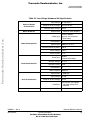
designed as a DSP system that meets the following general
performance requirements:
Freescale Semiconductor, Inc...
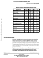
Table 2-1. Low Voltage Evaluation Hardware Set Specifications
Hardware Boards
Characteristics
Input voltage:
12 Vdc
Maximum dc-bus voltage:
16.0 V
Maximal output current:
Motor type:
Speed range:
Motor Characteristics
Drive Characteristics
Maximal line voltage:
< 5000 rpm (at 60 V)
60 V
2A
Output torque:
0.140 Nm (at 2 A)
Speed range:
< 1400 rpm
Input voltage:
12 Vdc
Maximum dc-bus voltage:
15.8 V
Type:
Designer Reference Manual
18
4 poles, three phase, star
connected, BLDC motor
Phase current:
Protection:
Load Characteristic
4.0 A
Over-current, over-voltage,
and under-voltage fault
protection
Varying
DRM027 — Rev 0
System Description
For More Information On This Product,
Go to: www.freescale.com
MOTOROLA
Freescale Semiconductor, Inc.
System Description
System Specification
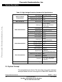
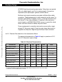
Table 2-2. Low Voltage Hardware Set Specifications
Input voltage:
Hardware Boards
Characteristics
Maximum dc-bus voltage:
Maximal output current:
Motor -Brake Set
Freescale Semiconductor, Inc...
3000 rpm (at 12 V)
150 W
Phase voltage:
3*6.5 V
Phase current:
17 A
SG40N
3-Phase BLDC Motor
Nominal Voltage:
3 x 27 V
Nominal Current:
2.6 A
Nominal Speed:
6
1500 rpm
Speed range:
< 2500 rpm
Input voltage:
12 Vdc
Maximum dc-bus voltage:
15.8 V
Protection:
Type:
DRM027 — Rev 0
MOTOROLA
EM Brno SM40N
3 phase, star connected
BLDC motor,
Speed range:
Pole-Number:
Load Characteristic
EM Brno, Czech Republic
6
Brake Type:
Drive Characteristics
50.0 A
Pole-Number:
Maximum electrical power:
Brake Characteristics
16.0 V or 55.0 V
Manufactured
Motor type:
Motor Characteristics
12 Vdc or 42 V
Over-current, over-voltage,
and under-voltage fault
protection
Varying
Designer Reference Manual
System Description
For More Information On This Product,
Go to: www.freescale.com
19
Freescale Semiconductor, Inc.
System Description
Table 2-3. High Voltage Evaluation Hardware Set Specifications
Input voltage:
Hardware Boards
Characteristics
Motor -Brake Set
Maximum dc-bus voltage:
407 V
Maximal output current:
2.93A
Manufactured
Freescale Semiconductor, Inc...
Motor type:
Motor Characteristics
Speed range:
2500 rpm (at 310 V)
150 W
Phase voltage:
3*220 V
Phase current:
0.55 A
SG40N
3-Phase BLDC Motor
Nominal Voltage:
3 x 27 V
Nominal Current:
2.6 A
Pole-Number:
Nominal Speed:
Speed range:
Maximum dc-bus voltage:
Optoisolation:
Protection:
Load Characteristic
EM Brno SM40V
3 phase, star connected
BLDC motor,
6
Brake Type:
Drive Characteristics
EM Brno, Czech Republic
Pole-Number:
Maximum electrical power:
Brake Characteristics
230 Vac or 115 Vac
Type:
6
1500 rpm
< 2500 rpm
(determined by motor used)
380 V
Required
Over-current, over-voltage,
and under-voltage fault
protection
Varying
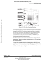
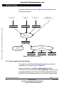
2.3 System Concept
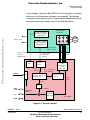
The concept below was chosen. The sensorless rotor position technique
developed detects the zero crossing points of Back-EMF induced in the
Designer Reference Manual
20
DRM027 — Rev 0
System Description
For More Information On This Product,
Go to: www.freescale.com
MOTOROLA
Freescale Semiconductor, Inc.
System Description
System Concept
motor windings. The phase Back-EMF Zero Crossing points are sensed
while one of the three phase windings is not powered. The obtained
information is processed in order to commutate the energized phase pair
and control the phase voltage, using Pulse Width Modulation
Freescale Semiconductor, Inc...
.
Three-Phase
Inverter
DC Bus Current &
DC Bus Voltage
Sensing
3-ph
BLDC
Motor
Power line
3 BEMF Voltage
Zero Crossing
Comparators
3 phase BLDC
Power Stage
DC-Bus Voltage/
Current
Temperature
3 BEMF Zero
Crossing
signals
ADC
Digital
Inputs
Zero
Crossing
PC Master
Zero Crossing
Time moment
Zero Crossing
Period, Position
Recognition
SCI
PWM
PWM
Generator
with
Dead Time
Commutation
Control
Commutation
Period
Duty
Cycle
1/T
START
STOP
UP
Atual Speed
Required
Speed
Speed PI
Regulator
DSP56F80x
DOWN
Figure 2-1. System Concept
DRM027 — Rev 0
MOTOROLA
Designer Reference Manual
System Description
For More Information On This Product,
Go to: www.freescale.com
21
Freescale Semiconductor, Inc.
System Description
Freescale Semiconductor, Inc...
The Back-EMF zero crossing detection enables position recognition.
The resistor network is used to divide sensed voltages down to a 0-3.3V
voltage level. Zero Crossing detection is synchronized with the center of
center aligned PWM signal by the SW in order to filter high voltage
spikes produced by the switching of the IGBTs (MOSFETs). This signal
is transferred to the DSP Encoder Input which is also used as a digital
filter. The SW selects one of the phase comparator outputs which
corresponds to the current commutation step.
Designer Reference Manual
22
DRM027 — Rev 0
System Description
For More Information On This Product,
Go to: www.freescale.com
MOTOROLA
Freescale Semiconductor, Inc.
Designer Reference Manual — 3-ph BLDC with Sensorless ZC Detection
Section 3. BLDC Motor Control
Freescale Semiconductor, Inc...
3.1 Contents
3.2
Brushless DC Motor Control Theory. . . . . . . . . . . . . . . . . . . . .23
3.3
Control Technique . . . . . . . . . . . . . . . . . . . . . . . . . . . . . . . . . . 40
3.2 Brushless DC Motor Control Theory
3.2.1 BLDC Motor Targeted by This Application
The Brushless DC motor (BLDC motor) is also referred to as an
electronically commuted motor. There are no brushes on the rotor and
the commutation is performed electronically at certain rotor positions.
The stator magnetic circuit is usually made from magnetic steel sheets.
The stator phase windings are inserted in the slots (distributed winding)
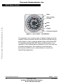
as shown in Figure 3-1 or it can be wound as one coil on the magnetic
pole. The magnetization of the permanent magnets and their
displacement on the rotor are chosen such a way that the Back-EMF (the
voltage induced into the stator winding due to rotor movement) shape is
trapezoidal. This allows the three phase voltage system (see
Figure 3-2), with a rectangular shape, to be used to create a rotational
field with low torque ripples.
The motor can have more then just one pole-pair per phase. This defines
the ratio between the electrical revolution and the mechanical revolution.
The BLDC motor shown has three pole-pairs per phase which represent
three electrical revolutions per one mechanical revolution.
DRM027 — Rev 0
MOTOROLA
Designer Reference Manual
BLDC Motor Control
For More Information On This Product,
Go to: www.freescale.com
23
Freescale Semiconductor, Inc.
BLDC Motor Control
Stator
Stator winding
(in slots)
Shaft
Freescale Semiconductor, Inc...
Rotor
Air gap
Permanent magnets
Figure 3-1. BLDC Motor - Cross Section
The rectangular, easy to create, shape of applied voltage ensures the
simplicity of control and drive. But the rotor position must be known at
certain angles in order to align the applied voltage with the Back-EMF.
The alignment between Back-EMF and commutation events is very
important. In this condition the motor behaves as a DC motor and runs
at the best working point. Thus simplicity of control and good
performance make this motor a natural choice for low-cost and
high-efficiency applications
Designer Reference Manual
24
DRM027 — Rev 0
BLDC Motor Control
For More Information On This Product,
Go to: www.freescale.com
MOTOROLA
Freescale Semiconductor, Inc.
BLDC Motor Control
Brushless DC Motor Control Theory
Freescale Semiconductor, Inc...
.
electrical
angle
Figure 3-2. Three Phase Voltage System
Figure 3-3 shows number of waveforms: the magnetic flux linkage, the
phase Back-EMF voltage and the phase-to-phase Back-EMF voltage.
The magnetic flux linkage can be measured; however in this case it was
calculated by integrating the phase Back-EMF voltage, which was
measured on the non-fed motor terminals of the BLDC motor. As can be
seen, the shape of the Back-EMF is approximately trapezoidal and the
amplitude is a function of the actual speed. During the speed reversal the
amplitude is changed its sign and the phase sequence change too.
The filled areas in the tops of the phase Back-EMF voltage waveforms
indicate the intervals where the particular phase power stage
commutations occur. As can be seen, the power switches are cyclically
commutated through the six steps. The crossing points of the phase
Back-EMF voltages represent the natural commutation points. In normal
operation the commutation is performed here. Some control techniques
advance the commutation by a defined angle in order to control the drive
above the PWM voltage control
DRM027 — Rev 0
MOTOROLA
Designer Reference Manual
BLDC Motor Control
For More Information On This Product,
Go to: www.freescale.com
25
Freescale Semiconductor, Inc.
BLDC Motor Control
Phase Magnetic Flux Linkage
Psi_A
Psi_B
Psi_C
Freescale Semiconductor, Inc...
Ph. A Ph. B
Ph. A
Atop
Btop
Ctop
Cbot Abot
Ph. C
Phase Back EMF
Ph. B
Ui_A
Ui_B
Ui_C
Ph. C
Speed reversal
“Natural” commutation point
Bbot
Acting power switch in the power stage
A-B
Phase-Phase Back EMF
Ui_AB
Ui_BC
Ui_CA
B-C
C-A
Figure 3-3. BLDC Motor - Back EMF and Magnetic Flux
3.2.2 3-Phase BLDC Power Stage
The voltage for 3-phase BLDC motor is provided by a 3-phase power
stage controlled by a DSP. The PWM module is usually implemented on
a DSP to create desired control signals.
A DSP with BLDC motor and power stage is shown in Figure 3-3.
Designer Reference Manual
26
DRM027 — Rev 0
BLDC Motor Control
For More Information On This Product,
Go to: www.freescale.com
MOTOROLA
Freescale Semiconductor, Inc.
BLDC Motor Control
Brushless DC Motor Control Theory
3.2.3 Why Sensorless Control?
As explained in the previous section, the rotor position must be known in
order to drive a Brushless DC motor. If any sensors are used to detect
rotor position, then sensed information must be transferred to a control
unit (see Figure 3-4)
Freescale Semiconductor, Inc...
.
AC Line Voltage
~
=
Power Stage
M
Position
Sensors
LOAD
Control Signals
Speed
Setting
Position
Feedback
Control Unit
Figure 3-4. Classical System
Therefore additional connections to the motor are necessary. This may
not be acceptable for some applications (see 1.3 Benefits of the
Solution).
3.2.4 Power Stage - Motor System Model
In order to explain and simulate the idea of Back-EMF sensing
techniques a simplified mathematical model based on the basic circuit
topology (see Figure 3-5) has been created.
DRM027 — Rev 0
MOTOROLA
Designer Reference Manual
BLDC Motor Control
For More Information On This Product,
Go to: www.freescale.com
27
Freescale Semiconductor, Inc.
Freescale Semiconductor, Inc...
BLDC Motor Control
Figure 3-5. Power Stage - Motor Topology
The second goal of the model is to find how the motor characteristics
depend on the switching angle. The switching angle is the angular
difference between a real switching event and an ideal one (at the point
where the phase to phase Back-EMF crosses zero).
The motor-drive model consists of a normal three phase power stage
plus a Brushless DC motor. The power for the system is provided by a
voltage source (Ud). Six semiconductor switches (SA/B/C t/b), controlled
elsewhere, allow the rectangular voltage waveforms (see Figure 3-2) to
be applied. The semiconductor switches and diodes are simulated as
ideal devices. The natural voltage level of the whole model is put at one
half of the dc-bus voltage. This simplifies the mathematical expressions.
Designer Reference Manual
28
DRM027 — Rev 0
BLDC Motor Control
For More Information On This Product,
Go to: www.freescale.com
MOTOROLA
Freescale Semiconductor, Inc.
BLDC Motor Control
Brushless DC Motor Control Theory
3.2.4.1 Mathematical Model
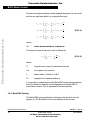
The following set of equations is valid for the presented topology:
Freescale Semiconductor, Inc...
C
1
u A = --- 2u VA – u VB – u VC +
u
∑ ix
3
x=A
uB
C
1
= --- 2u VB – u VC – u VA + ∑ u ix
3
x=A
uC
C
1
= --- 2u VC – u VA – u VB + ∑ u ix
3
x=A
(EQ 3-1.)
C
C
1
u O = --- ∑ u Vx – ∑ u ix
3
x = A
x=A
0 = iA + iB + iC
where:
u VA …u VC
are “branch” voltages; the voltages between one power stage
output and its virtual zero.
u A …u C
are motor phase winding voltages.
u iA …u iC
are phase Back-EMF voltages induced in the stator winding.
uO
is the voltage between the central point of the star of
motor winding and the power stage natural zero
i A …i C
are phase currents
The equations (EQ 3-1.) can be written taking into account the motor
phase resistance and the inductance. The mutual inductance between
DRM027 — Rev 0
MOTOROLA
Designer Reference Manual
BLDC Motor Control
For More Information On This Product,
Go to: www.freescale.com
29
Freescale Semiconductor, Inc.
BLDC Motor Control
the two motor phase windings can be neglected because it is very small
and has no significant effect for our abstraction level.
C
C
di A
1
u VA – u iA – --- ∑ u Vx – ∑ u ix = R ⋅ i A + L
dt
3
x = A
x=A
C
C
di B
1
u VB – u iB – --- ∑ u Vx – ∑ u ix = R ⋅ i B + L
dt
3
x = A
x=A
(EQ 3-2.)
Freescale Semiconductor, Inc...
C
C
di C
1
u VC – u iC – --- ∑ u Vx – ∑ u ix = R ⋅ i C + L
3
dt
x = A
x=A
where:
R,L
motor phase resistance, inductance
The internal torque of the motor itself is defined as:
1
T i = ---ω
C
∑
x=A
C
u ix ⋅ i x =
∑
x=A
dΨ x
⋅ ix
dθ
(EQ 3-3.)
where:
Ti
internal motor torque (no mechanical losses)
ω,θ
rotor speed, rotor position
x
phase index, it stands for A,B,C
Ψx
magnetic flux of phase winding x
It is important to understand how the Back-EMF can be sensed and how
the motor behavior depends on the alignment of the Back-EMF to
commutation events. This is explained in the next sections.
3.2.5 Back-EMF Sensing
The Back-EMF sensing technique is based on the fact that only two
phases of a DC Brushless motor are connected at a time (see
Designer Reference Manual
30
DRM027 — Rev 0
BLDC Motor Control
For More Information On This Product,
Go to: www.freescale.com
MOTOROLA
Freescale Semiconductor, Inc.
BLDC Motor Control
Brushless DC Motor Control Theory
Figure 3-2), so the third phase can be used to sense the Back-EMF
voltage.
Let us assume the situation when phases A and B are powered and
phase C is non-fed. No current is going through this phase. This is
described by the following conditions:
S Ab, S Bt ← are energized
Freescale Semiconductor, Inc...
1
− 1--- u , u
u VA = +
= ± --- u d
2 d VB
2
i A = – i B , i C = 0 , di C = 0
(EQ 3-4.)
u iA + u iB + u iC = 0
The branch voltage C can be calculated when considering the above
conditions:
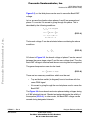
3
u VC = --- u iC
2
(EQ 3-5.)
AS shown in Figure 3-5, the branch voltage of phase C can be sensed
between the power stage output C and the zero voltage level. Thus the
Back-EMF voltage is obtained and the zero crossing can be recognized.
The general expressions can also be found:
3
u Vx = --- u ix where x = A ,B ,C
2
(EQ 3-6.)
There are two necessary conditions which must be met:
•
Top and bottom switch (in diagonal) have to be driven with the
same PWM signal
•
No current is going through the non-fed phase used to sense the
Back-EMF
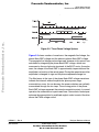
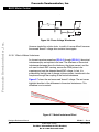
The Figure 3-6 shows branch and motor phase winding voltages during
a 0-360°electrical interval. Shaded rectangles designate the validity of
the equation (EQ 3-6.). In other words, the Back-EMF voltage can be
sensed during designated intervals
DRM027 — Rev 0
MOTOROLA
Designer Reference Manual
BLDC Motor Control
For More Information On This Product,
Go to: www.freescale.com
31
Freescale Semiconductor, Inc.
BLDC Motor Control
.
0
30
60
90
120
150
180
210
240
270
300
330
360
390
Freescale Semiconductor, Inc...
uVA
uA
Figure 3-6. Phase Voltage Waveforms
However simple this solution looks, in reality it is more difficult, because
the sensed “branch” voltage also contains some ripples.
3.2.5.1 Effect of Mutual Inductance
As shown in previous equations (EQ 3-4.) through (EQ 3-6.), the mutual
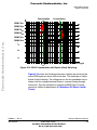
inductances play an important role here. The difference of the mutual
inductances between the coils which carry the phase current, and the
coil used for back-EMF sensing, causes the PWM pulses to be
superimposed onto the detected back-EMF voltage. In fact, it is
produced by the high rate of change of phase current, transferred to the
free phase through the coupling of the mutual inductance.
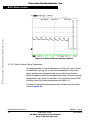
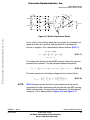
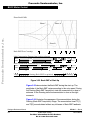
Figure 3-7 shows the real measured “branch” voltage. The red curves
highlight the effect of the difference in the mutual inductances. This
difference is not constant.
0V
Figure 3-7. Mutual Inductance Effect
Designer Reference Manual
32
DRM027 — Rev 0
BLDC Motor Control
For More Information On This Product,
Go to: www.freescale.com
MOTOROLA
Freescale Semiconductor, Inc.
BLDC Motor Control
Brushless DC Motor Control Theory
Due to the construction of the BLDC motor, both mutual inductances
vary. They are equal at the position that corresponds to the back-EMF
zero crossing detection.
Freescale Semiconductor, Inc...
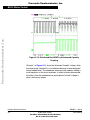
The branch waveform detail is shown in Figure 3-8. Channel 1 in
Figure 3-8 shows the disturbed “branch” voltage. The superimposed
ripples clearly match the width of the PWM pulses, and thus prove the
conclusions from the theoretical analysis.
The effect of the mutual inductance corresponds well in observations
carried out on the five different BLDC motors. These observations were
made during the development of the sensorless technique.
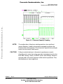
NOTE:
The BLDC motor with stator windings distributed in the slots has
technically higher mutual inductances than other types. Therefore, this
effect is more significant. On the other hand the BLDC motor with
windings wounded on separate poles, shows minor presence of the
effect of mutual inductance.
CAUTION:
However noticeable this effect, it does not degrade the back-EMF zero
crossing detection because it is cancelled at the zero crossing point.
Simple additional filtering helps to reduce ripples further.
DRM027 — Rev 0
MOTOROLA
Designer Reference Manual
BLDC Motor Control
For More Information On This Product,
Go to: www.freescale.com
33
Freescale Semiconductor, Inc.
Freescale Semiconductor, Inc...
BLDC Motor Control
Figure 3-8. Detail of Mutual Inductance Effect
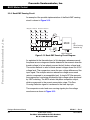
3.2.5.2 Effect of Mutual Phase Capacitance
The negative effect of mutual inductance is not the only one to disturb
the back-EMF sensing. So far, the mutual capacitance of the motor
phase windings was neglected in the motor model, since it affects
neither the phase currents nor the generated torque. Usually the mutual
capacitance is very small. Its influence is only significant during PWM
switching, when the system experiences very high du/dt.
The effect of the mutual capacitance can be studied using the model
shown in Figure 3-9.
Designer Reference Manual
34
DRM027 — Rev 0
BLDC Motor Control
For More Information On This Product,
Go to: www.freescale.com
MOTOROLA
Freescale Semiconductor, Inc.
BLDC Motor Control
Brushless DC Motor Control Theory
Id0
ud/2
+
=
A
S At
SBt
u VA
+
=
S Ab
u Cac
C
RC
RC
-
ud/2
iC
u Cba
ISb
SBb
C
iCab
-
uVB
iC
C
uVC Cap
C
RC
B
u Ccb
Freescale Semiconductor, Inc...
Figure 3-9. Mutual Capacitance Model
Let us focus on the situation when the motor phase A is switched from
negative dc-bus rail to positive, and the phase B is switched from
positive to negative. This is described by these conditions (EQ 3-7.):
S Ab, S Bt ← PWM
1
1
1
1
u VA = – --- u d → --- u d, u VB = --- u d → – --- u d
2
2
2
2
i Cac = i Ccb = i C
(EQ 3-7.)
The voltage that disturbs the back-EMF sensing, utilizing the free (not
powered) motor phase C, can be calculated based the equation:
u VC
Cap
1
1
= --- ( u Ccb + u Cac + 2R C ) – ( u Ccb + R C ) = --- ( u Cac – u Ccb )
2
2
(EQ 3-8.)
The final expression for disturbing voltage can be found as follows:
u VC
NOTE:
Cap
1
1 1
1 C cb – C ac
= --- -------- – -------- i C dt = --- ---------------------i dt
2 C ac C cb
2 C cb ⋅ C ac C
∫
(EQ 3-9.)
(EQ 3-9.) expresses the fact that only the unbalance of the mutual
capacitance (not the capacitance itself) disturbs the back-EMF sensing.
When both capacities are equal (they are balanced), the disturbances
disappear. This is demonstrated in Figure 3-10 and Figure 3-11.
DRM027 — Rev 0
MOTOROLA
∫
Designer Reference Manual
BLDC Motor Control
For More Information On This Product,
Go to: www.freescale.com
35
Freescale Semiconductor, Inc.
Freescale Semiconductor, Inc...
BLDC Motor Control
Figure 3-10. Distributed Back-EMF by Unbalanced Capacity
Coupling
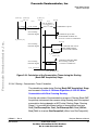
Channel 1 in Figure 3-11 shows the disturbed “branch” voltage, while
the other phase (channel 2) is not affected because it faces balanced
mutual capacitance. The unbalance was purposely made by adding a
small capacitor on the motor terminals, in order to better demonstrate
the effect. After the unbalance was removed the “branch” voltage is
clean, without any spikes.
Designer Reference Manual
36
DRM027 — Rev 0
BLDC Motor Control
For More Information On This Product,
Go to: www.freescale.com
MOTOROLA
Freescale Semiconductor, Inc.
Freescale Semiconductor, Inc...
BLDC Motor Control
Brushless DC Motor Control Theory
Figure 3-11. Balanced Capacity Coupling
NOTE:
The configuration of the phase windings end-turns has significant
impact; therefore, it needs to be properly managed to preserve the
balance in the mutual capacity. This is important, especially for prototype
motors that are usually hand-wound.
CAUTION:
Failing to maintain balance in the mutual capacitance can easily
disqualify such a motor from using sensorless techniques based on the
back-EMF sensing. Usually, the BLDC motors with windings wound on
separate poles show minor presence of the mutual capacitance. Thus,
the disturbance is also insignificant.
DRM027 — Rev 0
MOTOROLA
Designer Reference Manual
BLDC Motor Control
For More Information On This Product,
Go to: www.freescale.com
37
Freescale Semiconductor, Inc.
BLDC Motor Control
3.2.6 Back-EMF Sensing Circuit
An example of the possible implementation of the Back-EMF sensing
circuit is shown in Figure 3-12.
Freescale Semiconductor, Inc...
+DC_Bus Phase A Phase B Phase C
560k
560k
560k
560k
560k
560k
560k
560k
560k
560k
560k
560k
1n
1n
2x27k
1n
2x27k
2x27k
1n
MUX
Zero Crossing
Detection sig
2x27k
MUX Command
Figure 3-12. Back-EMF Sensing Circuit Diagram
As explained in the theoretical part of this designer reference manual,
the phase zero crossing event can be detected at the moment when the
branch voltage (of a free phase) crosses the half dc-bus voltage level.
The resistor network is used to divide sensed voltages down to a 0-15V
voltage level. The comparators sense the zero voltage difference of the
input signal. The multiple resistors reduce the voltage across each
resistor component to an acceptable level. A simple RC filter prevents
the comparators from being disturbed by high voltage spikes produced
by IGBT switching. The MUX selects the phase comparator output,
which corresponds to the current commutation stage. This Zero
Crossing Detection signal is transferred to the timer input pin.
The comparator control and zero crossing signals plus the voltage
waveforms are shown in Figure 3-13.
Designer Reference Manual
38
DRM027 — Rev 0
BLDC Motor Control
For More Information On This Product,
Go to: www.freescale.com
MOTOROLA
Freescale Semiconductor, Inc.
Freescale Semiconductor, Inc...
BLDC Motor Control
Brushless DC Motor Control Theory
Figure 3-13. The Zero Crossing Detection
The voltage drop resistor is used to measure the dc-bus current which is
chopped by the PWM. The obtained signal is rectified and amplified
(0-3.3V with 1.65V offset). The internal DSP A/D converter and Zero
Crossing detection are synchronized with the PWM signal. This
synchronization avoids spikes when the IGBTs (or MOSFETs) are
switching and simplifies the electric circuit.
The A/D converter is also used to sense the dc-bus voltage and drive
temperature. The dc-bus voltage is divided down to a 3.3V signal level
by a resistor network.
The six IGBTs (copack with built-in fly back diode) or MOSFETs and
gate drivers create a compact power stage. The drivers provide the level
shifting that is required to drive high side switch. PWM technique is used
to the control motor phase voltage.
DRM027 — Rev 0
MOTOROLA
Designer Reference Manual
BLDC Motor Control
For More Information On This Product,
Go to: www.freescale.com
39
Freescale Semiconductor, Inc.
BLDC Motor Control
3.3 Control Technique
3.3.1 Control Technique - General Overview
Freescale Semiconductor, Inc...
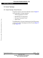
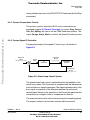
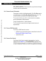
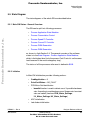
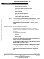
The general overview of used control technique is shown in Figure 2-1.
It will be described in following subsections:
•
PWM voltage generation for BLDC
•
Back-EMF Zero Crossing sensing
•
Sensorless Commutation Control
•
Speed Control
The implementation of the control technique with all the SW processes
is shown in Flow Chart, State diagrams and Data Flow (see Figure 5-1
through Figure 5-10).
Designer Reference Manual
40
DRM027 — Rev 0
BLDC Motor Control
For More Information On This Product,
Go to: www.freescale.com
MOTOROLA
Freescale Semiconductor, Inc.
BLDC Motor Control
Control Technique
3.3.2 PWM voltage Generation for BLDC.
3-PHASE POWER STAGE
Freescale Semiconductor, Inc...
PWM1
SAT
PWM3
SBT
B
PWM5
SCT
POWER
SOURCE
DC VOLTAGE
C
A
PWM2
SAB
PWM4
SBT
PWM6
SCT
3-PHASE BLDC MOTOR
MOSFET/IGBT DRIVERS
PWM1
PWM2 PWM3
PWM4 PWM5
PWM6
PULSE WIDTH MODULATOR
(PWM) MODULE
DSP56F805
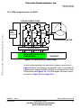
Figure 3-14. PWM with BLDC Power Stage
As was already explained, the three phase voltage system shown in
Figure 3-2 needs to be created to run the BLDC motor. It is provided by
3-phase power stage with 6 IGBTs (MOSFET) controlled by the on-chip
PWM module (see Figure 3-14). The PWM signals with state currents
are shown in Figure 3-15 and Figure 3-16.
DRM027 — Rev 0
MOTOROLA
Designer Reference Manual
BLDC Motor Control
For More Information On This Product,
Go to: www.freescale.com
41
Freescale Semiconductor, Inc.
BLDC Motor Control
Freescale Semiconductor, Inc...
commutation
commutation
commutation
commutation
commutation
commutation
commutation
PWM1 SAt
A-off
A-off
A-off
PWM2 SAb
A-off
A-off
A-off
PWM3 SBt
B-off
B-off
PWM4 SBb
B-off
B-off
PWM5 SCt
C-off
C-off
C-off
PWM6 SCb
C-off
C-off
C-off
IA
A-off
A-off
A-off
B-off
B-off
IB
C-off
IC
0
C-off
C-off
60
120
180
240
300
360
electrical angle
Figure 3-15. 3-phase BLDC Motor Commutation PWM Signal
Figure 3-15 shows that both Bottom and Top power switches of the
“free“ phase must be switched off. This is needed for any effective
control of Brushless DC motor with trapezoidal BEMF.
Designer Reference Manual
42
DRM027 — Rev 0
BLDC Motor Control
For More Information On This Product,
Go to: www.freescale.com
MOTOROLA
Freescale Semiconductor, Inc.
BLDC Motor Control
Control Technique
Commutation
Commutation
60
120
PWM1 SAt
PWM2 SAb
PWM3 SBt
PWM4 SBb
Freescale Semiconductor, Inc...
PWM5 SCt
PWM6 SCb
IA
IB
IC
electrical angle
Figure 3-16. BLDC Commutation with Bipolar (Hard) Switching
Figure 3-16 shows that the diagonal power switches are driven by the
same PWM signal as shown with arrow lines. This technique is called
bipolar (hard) switching. The voltage across the two connected coils is
always ±dc-bus voltage whenever there is a current flowing through
these coils. Thus the condition for successful BEMF Zero Crossing
sensing is fulfilled as described in 3.2 Brushless DC Motor Control
Theory.
DRM027 — Rev 0
MOTOROLA
Designer Reference Manual
BLDC Motor Control
For More Information On This Product,
Go to: www.freescale.com
43
Freescale Semiconductor, Inc.
BLDC Motor Control
3.3.3 BEMF Zero Crossing Sensing
3.3.3.1 BEMF Zero Crossing Checking
Freescale Semiconductor, Inc...
The BEMF Zero Crossing of the 3 phases is checked using hardware
comparators as described in 3.2 Brushless DC Motor Control Theory
The outputs of the comparators are led to Quadrature Decoder Inputs.
Where the digital filtration block is used to filter the spike on the Zero
Crossing signals.
The software selects the “free” phase at each commutation step and
reads the filtered signal to detect the BEMF Zero Crossing event.
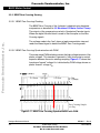
3.3.3.2 BEMF Zero Crossing Synchronization with PWM
The power stage PWM switching causes the high voltage transient of the
phase voltages. This transient is passed to “free” phase due to mutual
capacitor between the motor windings coupling. Figure 3-17 shows that
free phase “branch” voltage Uva is disturbed by PWM voltage shown on
phase “branch” voltage Uvb.
uva
uvb
Zero Crossing Sample
s/w flag
Figure 3-17. BEMF Zero Crossing Synchronization with PWM
Designer Reference Manual
44
DRM027 — Rev 0
BLDC Motor Control
For More Information On This Product,
Go to: www.freescale.com
MOTOROLA
Freescale Semiconductor, Inc.
BLDC Motor Control
Control Technique
Freescale Semiconductor, Inc...
The non-fed phase “branch” voltage Uva is disturbed at the PWM edges.
Therefore the presented BLDC Motor Control application synchronizes
the BEMF Zero Crossing detection with PWM.
DRM027 — Rev 0
MOTOROLA
Designer Reference Manual
BLDC Motor Control
For More Information On This Product,
Go to: www.freescale.com
45
Freescale Semiconductor, Inc.
BLDC Motor Control
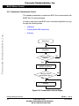
3.3.4 Sensorless Commutation Control
This chapter concentrates on sensorless BLDC motor commutation with
BEMF Zero Crossing technique.
Freescale Semiconductor, Inc...
In order to start and run the BLDC motor, the control algorithm has to go
through the following states:
•
Alignment
•
Starting (Back-EMF Acquisition)
•
Running
Start motor
Alignment
Alignment time
expired?
No
Yes
Starting
(BEMF Acquisition)
Minimal correct
commutations done?
No
Yes
Running
Figure 3-18. Commutation Control Stages
Designer Reference Manual
46
DRM027 — Rev 0
BLDC Motor Control
For More Information On This Product,
Go to: www.freescale.com
MOTOROLA
Freescale Semiconductor, Inc.
BLDC Motor Control
Control Technique
Figure 3-18 shows the transitions between the states. First the rotor is
aligned to a known position; then the rotation is started without the
position feedback. When the rotor moves, the Back-EMF is acquired so
the position is known and can be used to calculate the speed and
processing of the commutation in the Running state.
3.3.4.1 Alignment
Before
Freescale Semiconductor, Inc...
the motor starts, there is a short time (which depends on the
motor’s electrical time constant) when the rotor position is stabilized by
applying PWM signals to only two motor phases (no commutation). The
Current Controller keeps the current within predefined limits. This state
is necessary in order to create a high start-up torque. When the preset
time-out expires then this state is finished.
•
The Current Controller subroutine with PI regulator is called to
control dc-bus current. It sets the correct PWM ratio for the
required current.
The current PI controller works with constant execution (sampling)
period determined by PWM frequency: Current Controller period =
1/PWM frequency.
The BLDC motor rotor position with flux vectors during alignment is
shown in Figure 3-19.
DRM027 — Rev 0
MOTOROLA
Designer Reference Manual
BLDC Motor Control
For More Information On This Product,
Go to: www.freescale.com
47
Freescale Semiconductor, Inc.
Freescale Semiconductor, Inc...
BLDC Motor Control
Figure 3-19. Alignment
3.3.4.2 Running
The commutation process is the series of states which assure that the
Back-EMF zero crossing is successfully captured, the new commutation
time is calculated and, finally, the commutation is performed. The
following processes needs to be provided:
•
BLDC motor commutation service
•
Back-EMF Zero Crossing moment capture service
•
Computation of commutation times
•
Handler for interaction between these commutation processes
3.3.4.3 Algorithms BLDC Motor Commutation with Zero Crossing Sensing
All these processes are provided by new algorithms. They are described
in Section 6. Software Algorithms, 6.3 BLDC Motor Commutation
with Zero Crossing Sensing.
Designer Reference Manual
48
DRM027 — Rev 0
BLDC Motor Control
For More Information On This Product,
Go to: www.freescale.com
MOTOROLA
Freescale Semiconductor, Inc.
BLDC Motor Control
Control Technique
Freescale Semiconductor, Inc...
From pictures an overview of how the commutation works can be
understood. After commuting the motor phases there is a time interval
(Per_Toff[n]) when the shape of Back-EMF must stabilized (after the
commutation the fly-back diodes are conducting the decaying phase
current, therefore sensing of the Back-EMF is not possible). Then the
new commutation time (T2[n]) is preset. The new commutation will be
performed at this time if the Back-EMF zero crossing is not captured. If
the Back-EMF zero crossing is captured before the preset commutation
time expires, then the exact calculation of the commutation time (T2*[n])
is made based on the captured zero crossing time (T_ZCros[n]). The
new commutation is performed at this new time.
If (for any reason) the Back-EMF feedback is lost within one
commutation period corrective actions are taken in order to return to the
regular states.
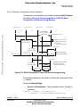
The flow chart explaining the principle of BLDC CommutationControl
with BEMF Zero Crossing Sensing is shown in Figure 3-20.
DRM027 — Rev 0
MOTOROLA
Designer Reference Manual
BLDC Motor Control
For More Information On This Product,
Go to: www.freescale.com
49
Freescale Semiconductor, Inc.
BLDC Motor Control
Commutation Done
No
BEMF Zero Crossing
detected between previous
commutations?
Corrective Calculation 1.
Freescale Semiconductor, Inc...
Yes
Service of Commutation:
Preset commutation
Wait for Per_Toff until phase
current decays to zero
Yes
BEMF Zero Crossing
missed?
BEMF Zero Crossing missed
Corrective Calculation 2.
corrected setting of
commutation time
No
Yes
BEMF Zero Crossing
Detected?
Service of received BEMF
Zero Crossing:
corrected setting of
commutation time
No
No
has commutation
time expired?
has commutation
time expired?
Yes
Yes
No
Make Motor Commutation
Figure 3-20. Flow Chart - BLDC Commutation
with BEMF Zero Crossing Sensing
Designer Reference Manual
50
DRM027 — Rev 0
BLDC Motor Control
For More Information On This Product,
Go to: www.freescale.com
MOTOROLA
Freescale Semiconductor, Inc.
BLDC Motor Control
Control Technique
3.3.4.4 Running - Commutation Times Calculation
Commutation time calculation is provided by algorithm bldcZCComput
described in Section 6. Software Algorithms, 6.3 BLDC Motor
Commutation with Zero Crossing Sensing.
T_Cmt0[n-2]
T_Cmt0[n-1]
n-1
n-2
Freescale Semiconductor, Inc...
T_Cmt0[n]
T_Next[n]
n
COEF_CMT_PRESET *
* Per_ZCrosFlt[n-1]
Commutation is preset
Commuted at preset time.
No Back-EMF feedback
was received
- Corrective Calculation 1.
Zero Crossing
Detection Signal
Per_ZCros[n]
T_Cmt0*[n+1]
Zero Crossing
Detection Signal
Per_ZCros[n-2]
Per_ZCros0[n] =
Per_ZCros[n-1]
Per_ZCros[n]
T_ZCros[n-1]
Per_HlfCmt[n]
T_ZCros[n]
Per_Toff[n]
T_Cmt0**[n+1]
Commuted when Back-EMF
Zero Crossing is missed
- Corrective Calculation 2.
Zero Crossing
Detection Signal
Per_ZCros[n]
Back-EMF feedback
received and evaluated
Per_HlfCmt[n]
Figure 3-21. BLDC Commutation Times with Zero Crossing sensing
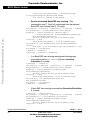
The following calculations are made to calculate the commutation times
(T_Next[n])
during the Running Stage:
•
Service of Commutation - The commutation time (T_Next[n]) is
predicted:
T_Next[n] = T_Cmt0[n] + Per_CmtPreset[n] =
= T_Cmt0[n] + Coef_CmtPrecomp*Per_ZCrosFlt[n-1]
DRM027 — Rev 0
MOTOROLA
Designer Reference Manual
BLDC Motor Control
For More Information On This Product,
Go to: www.freescale.com
51
Freescale Semiconductor, Inc.
BLDC Motor Control
coefficient Coef_CmtPrecomp = 2 at Running Stage!
If Coef_CmtPrecomp*Per_ZCrosFlt>Max_PerCmt
then result is limited at Max_PerCmt
•
Service of received Back-EMF zero crossing - The
commutation time (T_Next*[n]) is evaluated from the captured
Back-EMF zero crossing time (T_ZCros[n]):
Freescale Semiconductor, Inc...
Per_ZCros[n] = T_ZCros[n] - T_ZCros[n-1] = T_ZCros[n] - T_ZCros0
Per_ZCrosFlt[n] = (1/2*Per_ZCros[n]+1/2*Per_ZCros0)
HlfCmt[n] = 1/2*Per_ZCrosFlt[n]- Advance_angle =
= 1/2*Per_ZCrosFlt[n]- C_CMT_ADVANCE*Per_ZCrosFlt[n]=
Coef_HlfCmt*Per_ZCrosFlt[n]
The best commutation was get with Advance_angle:
60Deg*1/8 = 7.5Deg
which means Coef_HlfCmt = 0.375 at Running Stage!
Per_Toff[n+1] = Per_ZCrosFlt*Coef_Toff and Max_PerCmtProc
minimum
Coef_Toff = 0.35 at Running Stage, Max_PerCmtProc = 100!
Per_ZCros0 <-- Per_ZCros[n]
T_ZCros0 <-- T_ZCros[n]
T_Next*[n] = T_ZCros[n] + HlfCmt[n]
•
If no Back-EMF zero crossing was captured during preset
commutation period (Per_CmtPreset[n]) then Corrective
Calculation 1. is made:
T_ZCros[n] <-- CmtT[n+1]
Per_ZCros[n] = T_ZCros[n] - T_ZCros[n-1] = T_ZCros[n] - T_ZCros0
Per_ZCrosFlt[n] = (1/2*Per_ZCros[n]+1/2*Per_ZCros0)
HlfCmt[n] = 1/2*Per_ZCrosFlt[n]-Advance_angle =
Coef_HlfCmt*Per_ZCrosFlt[n]
The best commutation was get with Advance_angle:
60Deg*1/8 = 7.5Deg
which means Coef_HlfCmt = 0.375 at Running Stage!
Per_Toff[n+1] = Per_ZCrosFlt*Coef_Toff and
Max_PerCmtProc minimum
Per_ZCros0 <-- Per_ZCros[n]
T_ZCros0 <-- T_ZCros[n]
•
If Back-EMF zero crossing is missed then Corrective Calculation
2. is made:
T_ZCros[n] <-- CmtT[n]+Toff[n]
Per_ZCros[n] = T_ZCros[n] - T_ZCros[n-1] = T_ZCros[n] - T_ZCros0
Per_ZCrosFlt[n] = (1/2*T_ZCros[n]+1/2*T_ZCros0)
HlfCmt[n] = 1/2*Per_ZCrosFlt[n]-Advance_angle =
Coef_HlfCmt*Per_ZCrosFlt[n]
The best commutation was get with Advance_angle:
60Deg*1/8 = 7.5Deg
Designer Reference Manual
52
DRM027 — Rev 0
BLDC Motor Control
For More Information On This Product,
Go to: www.freescale.com
MOTOROLA
Freescale Semiconductor, Inc.
BLDC Motor Control
Control Technique
which means Coef_HlfCmt = 0.375 at Running Stage!
Per_ZCros0 <-- Per_ZCros[n]
T_ZCros0 <-- T_ZCros[n]
Freescale Semiconductor, Inc...
•
Where:
T_Cnt0 = time of the last commutation
T_Next = Time of the Next Time event (for Timer Setting)
T_zCros = Time of the last Zero Crossing
T_zCros0 = Time of the previous Zero Crossing
Per_Toff = Period of the Zero Crossing off
Per_CmtPreset = Preset Commutation Periof from commutation to
next commutation if no Zero Crossing was captured
Per_ZCros = Period between Zero Crossings (estimates required
commutation period)
Per_ZCros0 = Pervious period between Zero Crossings
Per_ZCrosFlt = Estimated period of commutation filtered
Per_HlfCmt = Period from Zero Crossing to commutation (half
commutation)
The required commutation timing is provided by setting of commutation
constants Coef_CmtPrecompFrac, Coef_CmtPrecompLShft,
Coef_HlfCmt, Coef_Toff, in structure RunComputInit.
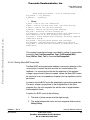
3.3.4.5 Starting (Back-EMF Acquisition)
The Back-EMF sensing technique enables a sensorless detection of the
rotor position, however the drive must be first started without this
feedback. It is caused by the fact that the amplitude of the induced
voltage is proportional to the motor speed. Hence, the Back-EMF cannot
be sensed at a very low speed and a special start-up algorithm must be
performed.
In order to start the BLDC motor the adequate torque must be generated.
The motor torque is proportional to the multiplication of the stator
magnetic flux, the rotor magnetic flux and the sine of angle between
these magnetic fluxes.
It implies (for BLDC motors) the following:
1. The level of phase current must be high enough.
2. The angle between the stator and rotor magnetic fields must be
90deg±30deg.
DRM027 — Rev 0
MOTOROLA
Designer Reference Manual
BLDC Motor Control
For More Information On This Product,
Go to: www.freescale.com
53
Freescale Semiconductor, Inc.
BLDC Motor Control
The first condition is satisfied during the Alignment state by keeping the
dc-bus current on the level which is sufficient to start the motor. In the
Starting (Back-EMF Acquisition) state the same value of PWM duty
cycle is used as the one which has stabilized the dc-bus current during
the Align state.
Freescale Semiconductor, Inc...
The second condition is more difficult to fulfill without any position
feedback information. After the Alignment state the stator and the rotor
magnetic fields are aligned (0deg angle). Therefore the two fast (faster
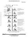
then the rotor can follow) commutations must be applied to create an
angular difference of the magnetic fields (see Figure 3-22).
The commutation time is defined by start commutation period
(Per_CmtStart).
This allows starting the motor such that minimal speed (defined by state
when Back-EMF can be sensed) is achieved during several
commutations while producing the required torque. Until the Back-EMF
feedback is locked the Commutation Process (explained in 3.3.4.2
Running) assures that commutations are done in advance, so that
successive Back-EMF zero crossing events are not missed.
After several successive Back-EMF zero crossings the exact
commutation times can be calculated. The commutation process is
adjusted and the control flow continues to the Running state. The BLDC
motor is then running with regular feedback and the speed controller can
be used to control the motor speed by changing the PWM duty cycle
value.
Designer Reference Manual
54
DRM027 — Rev 0
BLDC Motor Control
For More Information On This Product,
Go to: www.freescale.com
MOTOROLA
Freescale Semiconductor, Inc.
BLDC Motor Control
Control Technique
Motor is Running
at steady-state condition
with regular Back-EMF feedback
Rotor magnetic
Stator magnetic field
field
(created by PM)
Motor is Starting
Alignment Stage
The rotor position is stabilized by
applying PWM signals to only two
motor phases
Freescale Semiconductor, Inc...
Border of
stator pole
Rotor movement
during one
commutation
Zero crossing
edge indicator
Direction of
Phase current
Phase winding
Starting (BEMF Acquisition)
The two fast (faster then the rotor can
move) commutations are applied to
create an angular difference of the
stator magnetic field and rotor
magnetic field.
The Back-EMF feedback is tested.
When the Back-EMF zero crossing
is recognized the time of new
commutation is evaluated. Until at
least two successive Back-EMF zero
crossings are received the exact
commutation time can not be
calculated. Therefore the
commutation is done in advance in
order to assure that successive
Back-EMF zero crossing events
would not be missed.
Running
After several Back-EMF zero
crossing events the exact
commutation time is calculated. The
commutation process is adjusted.
Motor is running with regular
Back-EMF feedback.
Figure 3-22. Vectors of Magnetic Fields
DRM027 — Rev 0
MOTOROLA
Designer Reference Manual
BLDC Motor Control
For More Information On This Product,
Go to: www.freescale.com
55
Freescale Semiconductor, Inc.
BLDC Motor Control
Phase Back-EMFs
Phase A
Freescale Semiconductor, Inc...
Phase C
Phase B
Back-EMF Zero Crossings
Ideal Commutation Pattern when position is known
BTOP
CBOT
CTOP
ABOT
ATOP
BBOT
BTOP
CTOP
ABOT
BTOP
CTOP
CBOT
Real Commutation Pattern when position is estimated
BTOP
CBOT
1’st
ATOP
CTOP
ABOT
2’nd
Align
3’rd
BBOT
4’rd
CBOT
ABOT
.................
Starting (Back-EMF Acquisition)
Running
Figure 3-23. Back-EMF at Start-Up
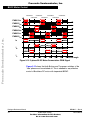
Figure 3-23 demonstrates the Back-EMF during the start-up. The
amplitude of the Back-EMF varies according to the rotor speed. During
the Starting (Back-EMF Acquisition) state the commutation is done in
advance. In the Running state the commutation is done at the right
moments.
Figure 3-24 illustrates the sequence of the commutations during the
Starting (Back-EMF Acquisition) Stage. The commutation times T2[1]
and T2[2] are calculated without any influence of Back-EMF feedback.
Designer Reference Manual
56
DRM027 — Rev 0
BLDC Motor Control
For More Information On This Product,
Go to: www.freescale.com
MOTOROLA
Freescale Semiconductor, Inc.
BLDC Motor Control
Control Technique
.
T_Cmt0[1] T_Cmt0[2]
T2[1]
n=1
T_Cmt0[3]
T2[2]
n=2
T2[n]
n=3
COEF_CMT_PRESET *
* Per_ZCrosFlt[n-1]
Per_CmtStart
Commutation is preset
2*Per_CmtStart
Freescale Semiconductor, Inc...
Zero Crossing
Detection Signal
Commuted at preset time.
No Back-EMF feedback was
received - Corrective Calculation 1.
T_ZCros[0]
T2*[n]
Zero Crossing
Detection Signal
Per_HlfCmt[n]
Commuted when correct
Back-EMF feedback
received and evaluated.
T_ZCros[n]
T2**[n]
Commuted when Back-EMF
Zero Crossing is missed
- Corrective Calculation 2.
Zero Crossing
Detection Signal
Per_Toff[n]
Per_HlfCmt[n]
Figure 3-24. Calculation of the Commutation Times during the Starting
(Back-EMF Acquisition) Stage
3.3.4.6 Starting - Commutation Times Calculation
The calculations made during Starting (Back-EMF Acquisition) Stage
can be seen in Section 6. Software Algorithms, 6.3 BLDC Motor
Commutation with Zero Crossing Sensing.
Even the sub-states of the commutation process of Starting (Back-EMF
Acquisition) state remain the same as during Running state, the required
commutation timing depends on MCS state (Starting Stage, Running
Stage). It is provided by different setting of commutation constants
Coef_CmtPrecompFrac, Coef_CmtPrecompLShft, Coef_HlfCmt,
Coef_Toff, in structure StartComputInit (differs from RunComputInit).
DRM027 — Rev 0
MOTOROLA
Designer Reference Manual
BLDC Motor Control
For More Information On This Product,
Go to: www.freescale.com
57
Freescale Semiconductor, Inc.
BLDC Motor Control
So the commutation times calculation is same as described in 3.3.4.4
Running - Commutation Times Calculation, but the following
computation coefficients are different:
Freescale Semiconductor, Inc...
coefficient Coef_CmtPrecomp = 2 at Starting Stage!
coefficient Coef_HlfCmt = 0.125 with advanced angle
Advance_angle: 60Deg*3/8 = 22.5Deg
at Starting Stage!
Coef_Toff = 0.5 at Running Stage, Max_PerCmtProc = 100!
3.3.5 Speed Control
The speed close loop control is provided by a well known PI regulator as
shown in 5.4.3 Process Speed PI Controller. The actual speed
(Omega_Actual) is computed from average of two BEMF Zero Crossing
periods (time intervals) received from the sensorless commutation
control block.
The speed controller works with constant execution (sampling) period
PER_SPEED_SAMPLE_S (request from timer interrupt).
Designer Reference Manual
58
DRM027 — Rev 0
BLDC Motor Control
For More Information On This Product,
Go to: www.freescale.com
MOTOROLA
Freescale Semiconductor, Inc.
Designer Reference Manual — 3-ph BLDC with Sensorless ZC Detection
Section 4. Hardware Design
Freescale Semiconductor, Inc...
4.1 Contents
4.2
System Configuration and Documentation . . . . . . . . . . . . . . . . 59
4.3
All HW Sets Components . . . . . . . . . . . . . . . . . . . . . . . . . . . . . 68
4.4
Low-Voltage Evaluation Motor Hardware Set Components . . . 70
4.5
Low-Voltage Hardware Set Components . . . . . . . . . . . . . . . . . 72
4.6
High-Voltage Hardware Set Components. . . . . . . . . . . . . . . . . 75
4.2 System Configuration and Documentation
The application is designed to drive the 3-phase BLDC motor. The HW
is a modular system composed from board and motor. There are three
possible hardware options:
•
High-Voltage Hardware Set Configuration
•
Low-Voltage Evaluation Motor Hardware Set Configuration
•
All HW Sets Components
Automatic board identification allows one software program runs on
each of three hardware and motor platforms without any change of
parameters
The following subsection shows the system configurations.
They systems consists of the following modules (see also Figure 4-3,
Figure 4-1, Figure 4-2):
For all hardware options:
•
DSP56F805EVM Controller Board
DRM027 — Rev 0
MOTOROLA
Designer Reference Manual
Hardware Design
For More Information On This Product,
Go to: www.freescale.com
59
Freescale Semiconductor, Inc.
Hardware Design
For High-Voltage Hardware Set cofiguration:
•
3-Phase AC/BLDC High Voltage Power Stage
•
Optoisolation Board
•
3-phase BLDC High Voltage Motor with Motor Brake
Freescale Semiconductor, Inc...
For Low-Voltage Evaluation Motor Hardware Set configuration:
•
EVM Motor Board
•
3-phase Low Voltage EVM BLDC Motor
Low-Voltage Hardware Set configuration:
•
3-Ph AC/BLDC Low Voltage Power Stage
•
3-phase BLDC Low Voltage Motor with Motor Brake
The sections 4.3 All HW Sets Components, 4.6 High-Voltage
Hardware Set Components, 4.4 Low-Voltage Evaluation Motor
Hardware Set Components and 4.5 Low-Voltage Hardware Set
Components will describe the individual boards.
Designer Reference Manual
60
DRM027 — Rev 0
Hardware Design
For More Information On This Product,
Go to: www.freescale.com
MOTOROLA
Freescale Semiconductor, Inc.
Freescale Semiconductor, Inc...
Hardware Design
System Configuration and Documentation
THIS PAGE INTENTIONALLY LEFT BLANK
DRM027 — Rev 0
MOTOROLA
Designer Reference Manual
Hardware Design
For More Information On This Product,
Go to: www.freescale.com
61
Freescale Semiconductor, Inc.
Hardware Design
4.2.1 Low-Voltage Evaluation Motor Hardware Set Configuration
The system configuration for a low-voltage evaluation motor hardware
set is shown in Figure 4-1.
40w flat
ribbon
cable
U2
Freescale Semiconductor, Inc...
+12
Evaluation
Motor Board
J3
GND
U1
Controller Board
J1
J30
(P1)
12VDC
DSP56805EVM
(DSP56803EVM)
J2
M1
Motor
ECMTREVAL
IB23810
Figure 4-1. Low-Voltage Evaluation Motor Hardware
System Configuration
All the system parts are supplied and documented according to the
following references:
•
M1 - IB23810 Motor
– supplied in kit with IB23810 Motor as: ECMTREVAL Evaluation Motor Board Kit
•
U2 3 ph AC/BLDC Low Voltage Power Stage:
– supplied in kit with IB23810 Motor as: ECMTREVAL Evaluation Motor Board Kit
– Described in: Motorola Embedded Motion Control Evaluation
Motor Board User’s Manual (Motorola document order number
MEMCEVMBUM/D) see References 5.
Designer Reference Manual
62
DRM027 — Rev 0
Hardware Design
For More Information On This Product,
Go to: www.freescale.com
MOTOROLA
Freescale Semiconductor, Inc.
Hardware Design
System Configuration and Documentation
•
U1 Controller Board for DSP56F805:
– supplied as: DSP56805EVM
– described in: DSP Evaluation Module Hardware User’s Manual
(Motorola document order number DSP56F805EVMUM/D),
see References 2.
Freescale Semiconductor, Inc...
The individual modules are described in some sections below. More
detailed descriptions of the boards can be found in comprehensive
User’s Manuals belonging to each board (References 2, 5). These
manuals are available on on the World Wide Web at:
http://www.motorola.com
The User’s Manual incorporates the schematic of the board, description
of individual function blocks and a bill of materials. An individual board
can be ordered from Motorola as a standard product.
DRM027 — Rev 0
MOTOROLA
Designer Reference Manual
Hardware Design
For More Information On This Product,
Go to: www.freescale.com
63
Freescale Semiconductor, Inc.
Hardware Design
4.2.2 Low-Voltage Hardware Set Configuration
The system configuration for low-voltage hardware set is shown in
Figure 4-2.
40w flat
ribbon
cable
Freescale Semiconductor, Inc...
U2
+12
J19
GND
J20
3ph AC/BLDC
Low Voltage
Power Stage
Controller Board
J30
(P1)
J13
ECLOVACBLDC
12VDC
MB1
J17
DSP56805EVM
(DSP56803EVM)
J18
Black
White
Red
J16
U1
Motor-Brake
SM40N
SG40N
Not Connected
Black
White
Red
J5
ECMTRLOVBLDC
Not Connected
Figure 4-2. Low-Voltage Hardware System Configuration
All the system parts are supplied and documented according to the
following references:
•
U1 Controller Board for DSP56F805:
– supplied as: DSP56805EVM
– described in: DSP Evaluation Module Hardware User’s Manual
(Motorola document order number DSP56F805EVMUM/D),
see References 2.
•
U2 — 3-Phase AC/BLDC Low Voltage Power Stage
– Supplied as: ECLOVACBLDC
Designer Reference Manual
64
DRM027 — Rev 0
Hardware Design
For More Information On This Product,
Go to: www.freescale.com
MOTOROLA
Freescale Semiconductor, Inc.
Hardware Design
System Configuration and Documentation
– Described in: Motorola Embedded Motion Control 3-Phase
BLDC Low-Voltage Power Stage User’s Manual (Motorola
document order number MEMC3PBLDCLVUM/D3), see
References 6.
•
MB1 - Motor-Brake SM40N + SG40N
– supplied as: ECMTRLOVBLDC
Freescale Semiconductor, Inc...
The individual modules are described in some sections below. More
detailed descriptions of the boards can be found in comprehensive
User’s Manuals belonging to each board (References 2, 6). These
manuals are available on on the World Wide Web at:
http://www.motorola.com
The User’s Manual incorporates the schematic of the board, description
of individual function blocks and a bill of materials. An individual board
can be ordered from Motorola as a standard product.
DRM027 — Rev 0
MOTOROLA
Designer Reference Manual
Hardware Design
For More Information On This Product,
Go to: www.freescale.com
65
Freescale Semiconductor, Inc.
Hardware Design
4.2.3 High-Voltage Hardware Set Configuration
The system configuration for a high-voltage hardware set is shown in
Figure 4-3.
+12VDC
GND
40w flat ribbon
cable
U2
Freescale Semiconductor, Inc...
L
N
PE
J14
J1
Optoisolation
Board
Controller Board
J2
ECOPT
100 - 240VAC
49 - 61 Hz
U1
JP1.1 JP1.2
3ph AC/BLDC
High Voltage
Power Stage
J11.1
J11.2
40w flat ribbon
cable
U3
J30
(P1)
DSP56805EVM
(DSP56803EVM)
Black
White
Red
J13.1 J13.2 J13.3
MB1
Motor-Brake
SM40V
SG40N
ECOPTHIVACBLDC
Not Connected
Black
White
Red
J5
ECMTRHIVBLDC
Not Connected
Figure 4-3. High-Voltage Hardware System Configuration
All the system parts are supplied and documented according to the
following references:
•
U1 Controller Board for DSP56F805:
– supplied as: DSP56805EVM
– described in: DSP Evaluation Module Hardware User’s Manual
(Motorola document order number DSP56F805EVMUM/D),
see References 2.
•
U2 — 3-Phase AC/BLDC High Voltage Power Stage:
– Supplied in kit with optoisolation board as:
ECOPTHIVACBLDC
Designer Reference Manual
66
DRM027 — Rev 0
Hardware Design
For More Information On This Product,
Go to: www.freescale.com
MOTOROLA
Freescale Semiconductor, Inc.
Hardware Design
System Configuration and Documentation
– Described in: 3-Phase AC Brushless DC High Voltage Power
Stage User’s Manual (Motorola document order number
MEMC3PBLDCPSUM/D), see References 3.
•
U3 — Optoisolation Board
– Supplied with 3-phase AC/BLDC high voltage power stage as:
ECOPTHIVACBLDC
– Or, supplied alone as: ECOPT–ECOPT optoisolation board
Freescale Semiconductor, Inc...
– Described in: Optoisolation Board User’s Manual (Motorola
document order number MEMCOBUM/D), see References 4.
NOTE:
It is strongly recommended to use opto-isolation (optocouplers and
optoisolation amplifiers) during development time to avoid any damage
to the development equipment.
•
MB1 — Motor-Brake SM40V + SG40N
– Supplied as: ECMTRHIVBLDC
The individual modules are described in some sections below. More
detailed descriptions of the boards can be found in comprehensive
User’s Manuals belonging to each board (References 2, 3, 4). These
manuals are available on on the World Wide Web at:
http://www.motorola.com
The User’s Manual incorporates the schematic of the board, description
of individual function blocks and a bill of materials. An individual board
can be ordered from Motorola as a standard product.
DRM027 — Rev 0
MOTOROLA
Designer Reference Manual
Hardware Design
For More Information On This Product,
Go to: www.freescale.com
67
Freescale Semiconductor, Inc.
Hardware Design
4.3 All HW Sets Components
4.3.1 DSP56F805EVM Controller Board
The DSP56F805EVM is used to demonstrate the abilities of the
DSP56F805 and to provide a hardware tool allowing the development of
applications that use the DSP56F805.
Freescale Semiconductor, Inc...
The DSP56F805EVM is an evaluation module board that includes a
DSP56F805 part, peripheral expansion connectors, external memory
and a CAN interface. The expansion connectors are for signal
monitoring and user feature expandability.
The DSP56F805EVM is designed for the following purposes:
•
Allowing new users to become familiar with the features of the
56800 architecture. The tools and examples provided with the
DSP56F805EVM facilitate evaluation of the feature set and the
benefits of the family.
•
Serving as a platform for real-time software development. The tool
suite enables the user to develop and simulate routines, download
the software to on-chip or on-board RAM, run it, and debug it using
a debugger via the JTAG/OnCETM port. The breakpoint features of
the OnCE port enable the user to easily specify complex break
conditions and to execute user-developed software at full-speed,
until the break conditions are satisfied. The ability to examine and
modify all user accessible registers, memory and peripherals
through the OnCE port greatly facilitates the task of the developer.
•
Serving as a platform for hardware development. The hardware
platform enables the user to connect external hardware
peripherals. The on-board peripherals can be disabled, providing
the user with the ability to reassign any and all of the DSP's
peripherals. The OnCE port's unobtrusive design means that all
of the memory on the board and on the DSP chip are available to
the user.
The DSP56F805EVM provides the features necessary for a user to write
and debug software, demonstrate the functionality of that software and
Designer Reference Manual
68
DRM027 — Rev 0
Hardware Design
For More Information On This Product,
Go to: www.freescale.com
MOTOROLA
Freescale Semiconductor, Inc.
Hardware Design
All HW Sets Components
interface with the customer's application-specific device(s). The
DSP56F805EVM is flexible enough to allow a user to fully exploit the
DSP56F805's features to optimize the performance of their product, as
shown in Figure 4-4.
Freescale Semiconductor, Inc...
DSP56F805
RESET
LOGIC
RESET
MODE/IRQ
LOGIC
MODE/IRQ
Program Memory
64Kx16-bit
Address,
Data &
Control
SPI
SCI #0
RS-232
Interface
DSub
9-Pin
CAN Interface
SCI #1
CAN
Data Memory
64Kx16-bit
4-Channel
10-bit D/A
Debug LEDs
Peripheral
Expansion
Connector(s)
PWM LEDs
TIMER
Over V Sense
GPIO
Over I Sense
Memory
Expansion
Connector(s)
JTAG
Connector
DSub
25-Pin
Zero Crossing
Detect
JTAG/OnCE
A/D
Parallel
JTAG
Interface
Low Freq
Crystal
PWM #1
PWM #2
XTAL/EXTAL
3.3 V & GND
Primary
UNI-3
Secondary
UNI-3
Power Supply
3.3V, 5.0V & 3.3VA
Figure 4-4. Block Diagram of the DSP56F805EVM
DRM027 — Rev 0
MOTOROLA
Designer Reference Manual
Hardware Design
For More Information On This Product,
Go to: www.freescale.com
69
Freescale Semiconductor, Inc.
Hardware Design
4.4 Low-Voltage Evaluation Motor Hardware Set Components
4.4.1 EVM Motor Board
Freescale Semiconductor, Inc...
Motorola’s embedded motion control series EVM motor board is a
12-volt, 4-amp, surface-mount power stage that is shipped with an MCG
IB23810-H1 brushless dc motor. In combination with one of the
embedded motion control series control boards, it provides a software
development platform that allows algorithms to be written and tested
without the need to design and build a power stage. It supports
algorithms that use Hall sensors, encoder feedback, and back EMF
(electromotive force) signals for sensorless control.
The EVM motor board does not have over-current protection that is
independent of the control board, so some care in its setup and use is
required if a lower impedance motor is used. With the motor that is
supplied in the kit, the power output stage will withstand a full-stall
condition without the need for over-current protection. Current
measuring circuitry is set up for 4 amps full scale. In a 25οC ambient
operation at up to 6 amps continuous RMS output current is within the
board’s thermal limits.
Input connections are made via 40-pin ribbon cable connector J1. Power
connections to the motor are made on output connector J2. Phase A,
phase B, and phase C are labeled on the board. Power requirements are
met with a single external 12-Vdc, 4-amp power supply. Two connectors,
labeled J3 and J4, are provided for the 12-volt power supply. J3 and J4
are located on the front edge of the board. Power is supplied to one or
the other, but not both.
4.4.1.1 Electrical Characteristics of the EVM Motor Board
The electrical characteristics in Table 4-1 apply to operation at 25°C and
a 12-Vdc power supply voltage.
Designer Reference Manual
70
DRM027 — Rev 0
Hardware Design
For More Information On This Product,
Go to: www.freescale.com
MOTOROLA
Freescale Semiconductor, Inc.
Hardware Design
Low-Voltage Evaluation Motor Hardware Set Components
Table 4-1. Electrical Characteristics of the EVM Motor Board
Freescale Semiconductor, Inc...
Characteristic
Symbol
Min
Typ
Max
Units
Power Supply Voltage
Vdc
10
12
16
V
Quiescent Current
ICC
—
50
—
mA
Min Logic 1 Input Voltage
VIH
2.4
—
—
V
Max Logic 0 Input Voltage
VIL
—
—
0.8
V
Input Resistance
RIn
—
10
—
kΩ
Analog Output Range
VOut
0
—
3.3
V
Bus Current Sense Voltage
ISense
—
412
—
mV/A
Bus Voltage Sense Voltage
VBus
—
206
—
mV/V
RDS(On)
—
32
40
MΩ
IM
—
—
6
A
Pdiss
—
—
5
W
Power MOSFET On Resistance
RMS Output Current
Total Power Dissipation
4.4.2 3-phase Low Voltage EVM BLDC Motor
The EVM Motor Board is shipped with an MCG IB23810-H1 brushless
dc motor. Motor-brake specifications are listed in Table 2-1, Section 2.
Other detailed motor characteristics are in Table 4-2 this section. They
apply to operation at 25°C.
Table 4-2. Characteristics of the BLDC motor
Characteristic
Terminal Voltage
Symbol
Min
Typ
Max
Units
Vt
—
—
60
V
—
5000
—
RPM
Speed @ Vt
Torque Constant
Kt
—
0.08
—
Nm/A
Voltage Constant
Ke
—
8.4
—
V/kRPM
Winding Resistance
Rt
—
2.8
—
Ω
Winding Inductance
L
—
8.6
—
mH
DRM027 — Rev 0
MOTOROLA
Designer Reference Manual
Hardware Design
For More Information On This Product,
Go to: www.freescale.com
71
Freescale Semiconductor, Inc.
Hardware Design
Table 4-2. Characteristics of the BLDC motor
Continuous Current
Ics
—
—
2
A
Peak Current
Ips
—
—
5.9
A
Inertia
Jm
—
0.075
—
kgcm2
—
—
3.6
°C/W
Thermal Resistance
Freescale Semiconductor, Inc...
4.5 Low-Voltage Hardware Set Components
4.5.1 3-Ph AC/BLDC Low Voltage Power Stage
Motorola’s embedded motion control series low-voltage (LV) brushless
DC (BLDC) power stage is designed to run 3-ph. BLDC and PM
Synchronous motors. It operates from a nominal 12-volt motor supply,
and delivers up to 30 amps of rms motor current from a dc-bus that can
deliver peak currents up to 46 amps. In combination with one of
Motorola’s embedded motion control series control boards, it provides a
software development platform that allows algorithms to be written and
tested, without the need to design and build a power stage. It supports a
wide variety of algorithms for controlling BLDC motors and PM
Synchronous motors.
Input connections are made via 40-pin ribbon cable connector J13.
Power connections to the motor are made with fast-on connectors J16,
J17, and J18. They are located along the back edge of the board, and
are labeled Phase A, Phase B, and Phase C. Power requirements are
met with a 12-volt power supply that has a 10- to 16-volt tolerance.
Fast-on connectors J19 and J20 are used for the power supply. J19 is
labeled +12V and is located on the back edge of the board. J20 is
labeled 0V and is located along the front edge. Current measuring
circuitry is set up for 50 amps full scale. Both bus and phase leg currents
are measured. A cycle by cycle over-current trip point is set at 46 amps.
The LV BLDC power stage has both a printed circuit board and a power
substrate. The printed circuit board contains MOSFET gate drive
circuits, analog signal conditioning, low-voltage power supplies, and
some of the large passive power components. This board also has a
Designer Reference Manual
72
DRM027 — Rev 0
Hardware Design
For More Information On This Product,
Go to: www.freescale.com
MOTOROLA
Freescale Semiconductor, Inc.
Hardware Design
Low-Voltage Hardware Set Components
68HC705JJ7 microcontroller used for board configuration and
identification. All of the power electronics that need to dissipate heat are
mounted on the power substrate. This substrate includes the power
MOSFETs, brake resistors, current-sensing resistors, bus capacitors,
and temperature sensing diodes. Figure 4-6 shows a block diagram.
Freescale Semiconductor, Inc...
POWER
INPUT
BIAS
POWER
BRAKE
MOSFET
POWER MODULE
SIGNALS
TO/FROM
CONTROL
BOARD
GATE
DRIVERS
TO
MOTOR
PHASE CURRENT
PHASE VOLTAGE
BUS CURRENT
BUS VOLTAGE
MONITOR
BOARD
ID BLOCK
ZERO CROSS
BACK-EMF SENSE
Figure 4-5. Block Diagram
DRM027 — Rev 0
MOTOROLA
Designer Reference Manual
Hardware Design
For More Information On This Product,
Go to: www.freescale.com
73
Freescale Semiconductor, Inc.
Hardware Design
4.5.1.1 Electrical Characteristics of the 3-Ph BLDC Low Voltage Power Stage
The electrical characteristics in Table 4-3 apply to operation at 25°C with
a 12-Vdc supply voltage.
Table 4-3. Electrical Chatacteristics of the 3-Ph BLDC
Low Voltage Power Stage
Freescale Semiconductor, Inc...
Characteristic
Symbol
Min
Typ
Max
Units
Motor Supply Voltage
Vac
10
12
16
V
Quiescent current
ICC
—
175
—
mA
Min logic 1 input voltage
VIH
2.0
—
—
V
Max logic 0 input voltage
VIL
—
—
0.8
V
Analog output range
VOut
0
—
3.3
V
Bus current sense voltage
ISense
—
33
—
mV/A
Bus voltage sense voltage
VBus
—
60
—
mV/V
IPK
—
—
46
A
Continuous output current
IRMS
—
—
30
A
Brake resistor dissipation
(continuous)
PBK
—
—
50
W
Brake resistor dissipation
(15 sec pk)
PBK(Pk)
—
—
100
W
Pdiss
—
—
85
W
Peak output current
(300 ms)
Total power dissipation
4.5.2 3-phase BLDC Low Voltage Motor with Motor Brake
The Low Voltage BLDC motor-brake set incorporates a 3-phase Low
Voltage BLDC motor EM Brno SM40N and attached BLDC motor brake
SG40N. The BLDCmotor has six poles. The incremental position
encoder is coupled to the motor shaft, and position Hall sensors are
mounted between motor and brake. They allow sensing of the position if
required by the control algorithm, which is not required in this sensorless
application. Detailed motor-brake specifications are listed in Table 2-2,
Section 2.
Designer Reference Manual
74
DRM027 — Rev 0
Hardware Design
For More Information On This Product,
Go to: www.freescale.com
MOTOROLA
Freescale Semiconductor, Inc.
Hardware Design
High-Voltage Hardware Set Components
4.6 High-Voltage Hardware Set Components
4.6.1 3-Phase AC/BLDC High Voltage Power Stage
Freescale Semiconductor, Inc...
Motorola’s embedded motion control series high-voltage (HV) ac power
stage is a 180-watt (one-fourth horsepower), 3-phase power stage that
will operate off of dc input voltages from 140 to 230 volts and ac line
voltages from 100 to 240 volts. In combination with one of the embedded
motion control series control boards and an optoisolation board, it
provides a software development platform that allows algorithms to be
written and tested without the need to design and build a power stage. It
supports a wide variety of algorithms for both ac induction and brushless
dc (BLDC) motors.
Input connections are made via 40-pin ribbon cable connector J14.
Power connections to the motor are made on output connector J13.
Phase A, phase B, and phase C are labeled PH_A, Ph_B, and Ph_C on
the board. Power requirements are met with a single external 140- to
230-volt dc power supply or an ac line voltage. Either input is supplied
through connector J11. Current measuring circuitry is set up for 2.93
amps full scale. Both bus and phase leg currents are measured. A
cycle-by-cycle over-current trip point is set at 2.69 amps.
The high-voltage ac power stage has both a printed circuit board and a
power substrate. The printed circuit board contains IGBT gate drive
circuits, analog signal conditioning, low-voltage power supplies, power
factor control circuitry, and some of the large, passive, power
components. All of the power electronics which need to dissipate heat
are mounted on the power substrate. This substrate includes the power
IGBTs, brake resistors, current sensing resistors, a power factor
correction MOSFET, and temperature sensing diodes. Figure 4-6
shows a block diagram.
DRM027 — Rev 0
MOTOROLA
Designer Reference Manual
Hardware Design
For More Information On This Product,
Go to: www.freescale.com
75
Freescale Semiconductor, Inc.
Hardware Design
HV POWER
INPUT
SWITCH MODE
POWER SUPPLY
3-PHASE IGBT
POWER MODULE
SIGNALS
TO/FROM
CONTROL
BOARD
Freescale Semiconductor, Inc...
PFC CONTROL
dc BUS BRAKE
3-PHASE AC
TO
MOTOR
GATE
DRIVERS
PHASE CURRENT
PHASE VOLTAGE
BUS CURRENT
BUS VOLTAGE
MONITOR
BOARD
ID BLOCK
ZERO CROSS
BACK-EMF SENSE
Figure 4-6. 3-Phase AC High Voltage Power Stage
4.6.1.1 Electrical Characteristics of the 3-Phase AC/BLDC High Voltage Power Stage
The electrical characteristics in Table 4-4 apply to operation at 25°C with
a 160-Vdc power supply voltage.
Designer Reference Manual
76
DRM027 — Rev 0
Hardware Design
For More Information On This Product,
Go to: www.freescale.com
MOTOROLA
Freescale Semiconductor, Inc.
Hardware Design
High-Voltage Hardware Set Components
Table 4-4. Electrical Characteristics of Power Stage
Freescale Semiconductor, Inc...
Characteristic
Symbol
Min
Typ
Max
Units
dc input voltage
Vdc
140
160
230
V
ac input voltage
Vac
100
208
240
V
Quiescent current
ICC
—
70
—
mA
Min logic 1 input voltage
VIH
2.0
—
—
V
Max logic 0 input voltage
VIL
—
—
0.8
V
Input resistance
RIn
—
10 kΩ
—
Analog output range
VOut
0
—
3.3
V
Bus current sense voltage
ISense
—
563
—
mV/A
Bus voltage sense voltage
VBus
—
8.09
—
mV/V
Peak output current
IPK
—
—
2.8
A
Brake resistor dissipation
(continuous)
PBK
—
—
50
W
Brake resistor dissipation
(15 sec pk)
PBK(Pk)
—
—
100
W
Pdiss
—
—
85
W
Total power dissipation
4.6.2 Optoisolation Board
Motorola’s embedded motion control series optoisolation board links
signals from a controller to a high-voltage power stage. The board
isolates the controller, and peripherals that may be attached to the
controller, from dangerous voltages that are present on the power stage.
The optoisolation board’s galvanic isolation barrier also isolates control
signals from high noise in the power stage and provides a noise-robust
systems architecture.
Signal translation is virtually one-for-one. Gate drive signals are passed
from controller to power stage via high-speed, high dv/dt, digital
optocouplers. Analog feedback signals are passed back through
DRM027 — Rev 0
MOTOROLA
Designer Reference Manual
Hardware Design
For More Information On This Product,
Go to: www.freescale.com
77
Freescale Semiconductor, Inc.
Hardware Design
HCNR201 high-linearity analog optocouplers. Delay times are typically
250 ns for digital signals, and 2 µs for analog signals. Grounds are
separated by the optocouplers’ galvanic isolation barrier.
Freescale Semiconductor, Inc...
Both input and output connections are made via 40-pin ribbon cable
connectors. The pin assignments for both connectors are the same. For
example, signal PWM_AT appears on pin 1 of the input connector and
also on pin 1 of the output connector. In addition to the usual motor
control signals, an MC68HC705JJ7CDW serves as a serial link, which
allows controller software to identify the power board.
Power requirements for controller side circuitry are met with a single
external 12-Vdc power supply. Power for power stage side circuitry is
supplied from the power stage through the 40-pin output connector.
4.6.2.1 Electrical Characteristics of the Optoisolation Board
The electrical characteristics in Table 4-5 apply to operation at 25°C,
and a 12-Vdc power supply voltage
.
Table 4-5. Electrical Characteristics
Characteristic
Symbol
Min
Typ
Max
Units
Notes
Power Supply Voltage
Vdc
10
12
30
V
Quiescent Current
ICC
70(1)
200(2)
500(3)
mA
dc/dc converter
Min Logic 1 Input Voltage
VIH
2.0
—
—
V
HCT logic
Max Logic 0 Input Voltage
VIL
—
—
0.8
V
HCT logic
Analog Input Range
VIn
0
—
3.3
V
Input Resistance
RIn
—
10
—
kΩ
Analog Output Range
VOut
0
—
3.3
V
Digital Delay Time
tDDLY
—
0.25
—
µs
Analog Delay Time
tADLY
—
2
—
µs
1. Power supply powers optoisolation board only.
2. Current consumption of optoisolation board plus DSP EMV board (powered from this power supply)
3. Maximum current handled by dc/dc converters
Designer Reference Manual
78
DRM027 — Rev 0
Hardware Design
For More Information On This Product,
Go to: www.freescale.com
MOTOROLA
Freescale Semiconductor, Inc.
Hardware Design
High-Voltage Hardware Set Components
4.6.3 3-phase BLDC High Voltage Motor with Motor Brake
Freescale Semiconductor, Inc...
The High Voltage BLDC motor-brake set incorporates a 3-phase High
Voltage BLDC motor and attached BLDC motor brake. The BLDCmotor
has six poles. The incremental position encoder is coupled to the motor
shaft, and position Hall sensors are mounted between motor and brake.
They allow sensing of the position if required by the control algorithm.
Detailed motor-brake specifications are listed in Table 2-3, Section 2.
DRM027 — Rev 0
MOTOROLA
Designer Reference Manual
Hardware Design
For More Information On This Product,
Go to: www.freescale.com
79
Freescale Semiconductor, Inc.
Freescale Semiconductor, Inc...
Hardware Design
Designer Reference Manual
80
DRM027 — Rev 0
Hardware Design
For More Information On This Product,
Go to: www.freescale.com
MOTOROLA
Freescale Semiconductor, Inc.
Designer Reference Manual — 3-ph BLDC with Sensorless ZC Detection
Section 5. Software Design
Freescale Semiconductor, Inc...
5.1 Contents
5.2
Introduction . . . . . . . . . . . . . . . . . . . . . . . . . . . . . . . . . . . . . . . . 81
5.3
Main SW Flow Chart. . . . . . . . . . . . . . . . . . . . . . . . . . . . . . . . . 81
5.4
Data Flow . . . . . . . . . . . . . . . . . . . . . . . . . . . . . . . . . . . . . . . . . 84
5.5
State Diagram. . . . . . . . . . . . . . . . . . . . . . . . . . . . . . . . . . . . . . 89
5.2 Introduction
This section describes the design of the software blocks of the drive.
The software will be described in terms of:
•
Main SW Flow Chart
•
Data Flow
•
State Diagram
For more information on the control technique used see 3.3 Control
Technique.
5.3 Main SW Flow Chart
The main software flow chart incorporates the Main routine entered from
Reset, and interrupt states. The Main routine includes the initialization of
the DSP and the main loop. It is shown in Figure 5-1 and Figure 5-2.
The main loop incorporates Application State Machine - the highest SW
level which precedes settings for other software levels, BLDC motor
Commutation Control, Speed Control, Alignment Current Control, etc.
The inputs of Application State Machine are Run/Stop Switch state,
DRM027 — Rev 0
MOTOROLA
Designer Reference Manual
Software Design
For More Information On This Product,
Go to: www.freescale.com
81
Freescale Semiconductor, Inc.
Software Design
Required Speed Omega and Drive Fault Status. Required Mechanical
Speed can be set from PC Master or manually with Up/Down buttons.
Commutation Control proceeds BLDC motor commutation with the
states described in 3.3 Control Technique and 5.5.4 State Diagram Process Commutation Control.
Freescale Semiconductor, Inc...
The Speed Control is detailed description is in sections 5.4.3 Process
Speed PI Controller and 5.5.5 State Diagram - Process Speed PI
Controller. Alignment Current Control is described in 5.4.4 Process
Current PI Controller and 5.5.6 State Diagram - Process Current PI
Controller.
Run/Stop switch is checked to provide an input for Application State
Machine (ApplicationMode Start or Stop).
The interrupt subroutines provide commutation Timer services, ADC
starting in the PWM reload interrupt, ADC service, ADC Zero Crossing
checking, Limit analog values handling, over-current and over-voltage
PWM fault handler.
The Commutation Timer ISR is used for Commutation Timing and
Commutation Control and Zero Crossing Checking proceeding.
The Speed/Alignment Timer ISR is used for Speed regulator time base
and for Alignment stage duration timing.
The PWM Reload ISR is used to evaluate BEMF Zero Crossing, start
A/D conversion and memorize Zero Crossing sampling time
T_ZCSample.
The ADC Complete ISR is used to read voltages, current and
temperature samples from the ADC. It also sets Current control and
when the Current Control setting is enabled.
The other interrupts in Figure 5-2 are used for System Fault handling
and setting of Required Mechanical Speed input for Application State
Machine (ApplicationMode Start or Stop).
Designer Reference Manual
82
DRM027 — Rev 0
Software Design
For More Information On This Product,
Go to: www.freescale.com
MOTOROLA
Freescale Semiconductor, Inc.
Software Design
Main SW Flow Chart
Reset
Initialize
Interrupt
OC Cmt Timer
Freescale Semiconductor, Inc...
Application State Machine:
precedes/sets requirements of:
Drive Fault Status
Application Mode
Omega Required Mechanical
Control Speed
Control Alignment Current
Commutation Control
proceed Status_Commutation:
Running
Starting
Alignment
Stopped
Check Run/Stop Switch
Interrupt
ADC complete
ADC complete ISR:
read Temperature
dc-bus Voltage/Current
set Current Control Rq
Commutation Timer OC ISR:
Motor Commutation Timing
Commutate. Control Proceed
Zero Crossing Setting
RTI
Interrupt
OC Cmt2Timer
Speed/Alignment Timer OC ISR:
set Speed Control Request
Alignment stage timing
RTI
Interrupt
PWM A Reload
PWM Reload ISR:
start ADC
memorize sampling time
evaluate Zero Crossing
RTI
RTI
Figure 5-1. Main Software Flow Chart - Part 1
DRM027 — Rev 0
MOTOROLA
Designer Reference Manual
Software Design
For More Information On This Product,
Go to: www.freescale.com
83
Freescale Semiconductor, Inc.
Freescale Semiconductor, Inc...
Software Design
Interrupt
Up Button
Interrupt
Down Button
Up Button ISR:
increment
Omega Required Mechanical
Down Button ISR:
decrement
Omega Required Mechanical
RTI
RTI
Interrupt
ADC High Limit
Interrupt
ADC Low Limit
ADC Low Limit ISR:
set Under-voltage Fault
set Over-heating Fault
Emergency Stop
ADC High Limit ISR:
set Over-voltage Fault
set Over-current Fault
Emergency Stop
RTI
RTI
Interrupt
PWM A Fault
PWM Fault ISR:
set Over-current Fault
set Over-voltage Fault
Emergency Stop
RTI
Figure 5-2. Main Software Flow Chart - Part 2
5.4 Data Flow
The control algorithm obtains values from the user interface and
sensors, processes them and generates 3-phase PWM signals for motor
control as can be seen on the data flow analysis shown in Figure 5-3.
Designer Reference Manual
84
DRM027 — Rev 0
Software Design
For More Information On This Product,
Go to: www.freescale.com
MOTOROLA
Freescale Semiconductor, Inc.
Software Design
Data Flow
Dc-bus Current
(A/D)
I_Dc_Bus
Manual Speed
Setting
PC
Master
Omega_Required_Mech
BEMF Zero Crossing
Comparators
START/STOP
Switch
ApplicationMode
Freescale Semiconductor, Inc...
Process
Application
State Machine
Status_Commutation
Cmd_Application
Omega_Desired_Mech
BldcMode
Process
Commutation Control
Omega_Actual_Mech
Process
Current PI Controller
Process
Speed PI Controller
Step_Cmt,
Cmt_Drv_RqFlag
U_Desired
Process
PWM Generation
PVAL0,PVAL1
PVAL2,PVAL3
PVAL4,PVAL5
Figure 5-3. Data Flow - Part 1
DRM027 — Rev 0
MOTOROLA
Designer Reference Manual
Software Design
For More Information On This Product,
Go to: www.freescale.com
85
Freescale Semiconductor, Inc.
Software Design
Protection processes are shown in Figure 5-4 and described in the
following sub-sections.
Dc-bus Current
(A/D)
Temperature
(A/D)
Temperature
Freescale Semiconductor, Inc...
I_Dc_Bus
PWM Faults
Dc-bus Voltage
(A/D)
(Over-voltage/Over-current)
U_Dc_Bus
Process
Fault Control
DriveFaultStatus
Process
Application
State Machine
Process
PWM Generation
PVAL0,PVAL1
PVAL2,PVAL3
PVAL4,PVAL5
Figure 5-4. Data Flow - Part 2
5.4.1 Process Application State Machine
This process controls the application subprocesses by status and
command words as can be seen in Figure 5-3.
Based on the status of the Status_Commutation (set by the
Commutation Control process) the Cmd_Application Rq flags are set
to request calculation of the Current PI Controller (Alignment state) or
Speed PI Controller (Running state) and to control the angular speed
Designer Reference Manual
86
DRM027 — Rev 0
Software Design
For More Information On This Product,
Go to: www.freescale.com
MOTOROLA
Freescale Semiconductor, Inc.
Software Design
Data Flow
setting (reflects the status of the START/STOP Switch and the Run/Stop
commands).
5.4.2 Process Commutation Control
Freescale Semiconductor, Inc...
This process controls sensorless BLDC motor commutations as
explained in section 3.3 Control Technique. Its outputs, Step_Cmt and
Cmt_Drv_RqFlag, are used to set the PWM Generation process. The
output Omega_Actual_Mech is used for the Speed Controller process.
5.4.3 Process Speed PI Controller
The general principle of the speed PI control loop is illustrated in
Figure 5-5.
Reference
Speed
(Omega_Desired)
Speed
Error
PI
Controller
Corrected
Speed
(U_Desired)
Controlled
System
Actual Motor
Speed
(Omega_Actual)
Figure 5-5. Closed Loop Control System
The speed closed loop control is characterized by the feedback of the
actual motor speed. This information is compared with the reference set
point and the error signal is generated. The magnitude and polarity of the
error signal corresponds to the difference between the actual and
desired speed. Based on the speed error, the PI controller generates the
corrected motor voltage in order to compensate for the error.
The speed controller works with a constant execution (sampling) period.
The request is driven from the timer interrupt with the constant
DRM027 — Rev 0
MOTOROLA
Designer Reference Manual
Software Design
For More Information On This Product,
Go to: www.freescale.com
87
Freescale Semiconductor, Inc.
Software Design
PER_SPEED_SAMPLE_S. The PI controller is proportional and integral
constants were set experimentally.
5.4.4 Process Current PI Controller
Freescale Semiconductor, Inc...
The process is similar to the Speed controller. The I_Dc_Bus current is
controlled based on the U_Dc_Bus_Desired Reference current. The
current controller is processed only during Alignment stage.
The current controller works with a constant execution (sampling)
period. determined by PWM frequency:
Current Controller period = 1/pwm frequency.
The PI controller is proportional and integral constants were set
experimentally.
5.4.5 Process PWM Generation
The Process PWM Generation creates:
•
the BLDC motor commutation pattern as described in section 3.2
Brushless DC Motor Control Theory
•
required duty cycle
5.4.6 Process Fault Control
The Process Fault Control is used for drive protection. It can be
understood from Figure 5-4. The DriveFaultStatus is passed to the
PWM Generation process and to the Application State Machine process
in order to disable the PWMs and to control the application accordingly.
Designer Reference Manual
88
DRM027 — Rev 0
Software Design
For More Information On This Product,
Go to: www.freescale.com
MOTOROLA
Freescale Semiconductor, Inc.
Software Design
State Diagram
5.5 State Diagram
The state diagrams of the whole SW are described below.
5.5.1 Main SW States - General Overview
Freescale Semiconductor, Inc...
The SW can be split into following processes:
•
Process Application State Machine
•
Process Commutation Control
•
Process Speed PI Controller
•
Process Current PI Controller
•
Process PWM Generation
•
Process PWM Generation
as shown in <link>Section 5.4. The general overview of the software
states is in the State Diagram - Process Application State Machine,
which is the highest level (only the process Fault Control is on the same
level because of the motor emergency stop).
The status of all the processes after reset is defined in 5.5.2.
5.5.2 Initialize
In Main SW initialization provides following actions:
•
CmdApplication = 0
•
DriveFaultStatus = NO_FAULT
•
PCB Motor Set Identification
– boardId function is used to detect one of 3 possible hardware
sets. According to used hardware one of three control constant
sets are loaded (functions EVM_Motor_Settings,
LV_Motor_Settings, HV_Motor_Settings)
•
ADC Initialization
•
Led diodes initialization
DRM027 — Rev 0
MOTOROLA
Designer Reference Manual
Software Design
For More Information On This Product,
Go to: www.freescale.com
89
Freescale Semiconductor, Inc.
Freescale Semiconductor, Inc...
Software Design
NOTE:
•
Switch (Start/Stop) initialization
•
Push Buttons (Speed up/down) initialization
•
Commutation control initialization
•
PWM initialization
•
PWM fault interrupts initialization
•
Zero Crossing inputs = Quadrature decoder filter initialization
•
Output Compare Timers initialization
The EVM board can be connected to the power stage boards. In order
to assure the right hardware is connected the board identification is
performed. When inappropriate hardware is detected the
DriveFaultStatus|=WRONG_HARDWARE is set, motor remains
stopped!
5.5.3 State Diagram - Process Application State Machine
Process Application State Machine state diagram is displayed in
Figure 5-6. Application State Machine controls the main application
functionality.
The application can be controlled:
•
manually
•
from PC Master
In manual control, the application is controlled with Start/Stop switch and
Up Down Push buttons to set Required Speed.
In PC Master control mode the Start/Stop is controlled manually and the
Required Speed is set via the PC Master.
The motor is stopped whenever the absolute value of Required speed is
lower then Minimal Speed or switch set to stop or if there is a system
failure - Drive Fault (Emergency Stop) state is entered. All the SW
processes are controlled according this Application State Machine
status.
Designer Reference Manual
90
DRM027 — Rev 0
Software Design
For More Information On This Product,
Go to: www.freescale.com
MOTOROLA
Freescale Semiconductor, Inc.
Software Design
State Diagram
Reset
PC Master
Required Speed setting
Up Button
Down Button
Increment
Required Speed
Decrement
Required Speed
Set
Required Speed
Freescale Semiconductor, Inc...
(Switch = Stop) || (abs (Required Speed) <= Minimal Speed)
Bldc Run
with Required Speed
Bldc Stop
(Switch = Run) & (abs (Required Speed) > Minimal Speed)
Drive Fault
Drive Fault
Drive Fault
Emergency Stop
Figure 5-6. State Diagram - Process Application State Machine
5.5.4 State Diagram - Process Commutation Control
State Diagram of the process Commutation Control is shown in
Figure 5-7. The Commutation Control process takes care of the
sensorless BLDC motor commutation. The requirement to run the BLDC
motor is determined by upper software level Application State Machine.
When the Application State Machine is in BLDC Stop state,
Commutation Control status is Stopped. If it is in BLDC Stop state, the
Commutation Control goes through the states described in section 3.3
Control Technique. So there are the following possible states:
•
Alignment state
DRM027 — Rev 0
MOTOROLA
Designer Reference Manual
Software Design
For More Information On This Product,
Go to: www.freescale.com
91
Freescale Semiconductor, Inc.
Software Design
– motor is powered with current through 2 phases - no
commutations provided.
•
Starting (Back-EMF Acquisition) State
– motor is started with making first 2 commutations, then it is
running as at Running state using Start parameters for
commutation calculation StartComputInit (so the
commutation advance angle and the Per_Toff time are
different)
Freescale Semiconductor, Inc...
•
Running state
– motor is running with Run parameters for commutation
calculation RunComputInit.
•
Stopped state
– motor is stopped with no power going to motor phases.
The drive starts by setting the Alignment stage where the Alignment
commutation step is set and Alignment stage is timed. After the time-out
the Starting stage is entered with initialization of BEMF Zero Crossing
algorithms. After the required number of successive commutations with
correct Zero Crossing are done, the Running stage is entered. If the
number of commutations with wrong Zero Crossing exceeds a
pre-determined Maximal number, the Running and Starting stages are
exited to the Stop stage. The commutation control is determined by the
variable StatusCommutation.
Designer Reference Manual
92
DRM027 — Rev 0
Software Design
For More Information On This Product,
Go to: www.freescale.com
MOTOROLA
Freescale Semiconductor, Inc.
Software Design
State Diagram
Reset
Set Alignment
BLDC Run
done
Alignment
Stopped
Alignment Time-out
Freescale Semiconductor, Inc...
BLDC Stop
Set Starting
Set Stop
done
Starting
exceeded Maximal
Zero Crossing
Error commutations
Running
Set Running
done
Minimal commutations
with Zero Crossing OK
passed
Figure 5-7. State Diagram - Process Commutation Control
5.5.4.1 Commutation Control - Running State
The State diagram of Commutation Control state Running is shown in
Figure 5-8 and is explained in 3.3 Control Technique. The selection of
the state after the motor commutation depends on the detection of the
BEMF Zero Crossing during previous commutation period. If no BEMF
Zero Crossing was detected, the commutation period is corrected using
Corrective Calculation 1. Then the Next Commutation time and
commutation registers are preset. If Zero Crossing already happen
during Per_Toff time period, the commutation period is corrected using
Corrective Calculation 2. When the commutation time expires, then a
new commutation is performed.
DRM027 — Rev 0
MOTOROLA
Designer Reference Manual
Software Design
For More Information On This Product,
Go to: www.freescale.com
93
Freescale Semiconductor, Inc.
Software Design
Running - Begin
No Zero Crossing
detected during last
commutation period
motor Commutation
Calculate Next Commutation
after No Zero Crossing
Freescale Semiconductor, Inc...
Corrective Calculation 1.
commutation time
(T_Next) expired
Zero Crossing
Detected/Missed during last
commutation period
Preset Next Commutation
settings and timing
Zero Crossing Get
Calculate Next Commutation
after Zero Crossing Get
Zero Crossing Missed
during Per_Toff
Calculate Next Commutation
after Zero Crossing Missed
Corrective Calculation 2.
Figure 5-8. Substates - Running
This state is almost wholly serviced by the BLDC Zero Crossing
algorithms which are documented in Section 6. Software Algorithms,
6.3 BLDC Motor Commutation with Zero Crossing Sensing. First the
bldczcHndlr is called with actual time from Cmt Timer Counter to control
requests and commutation control registers. Other BLDC Zero Crossing
algorithms are called, according to the request flags. The state services
are located in main loop and in Cmt (commutation) Timer Interrupt.
5.5.4.2 Commutation Control - Starting state
The Starting state is as the the Running state as described in Figure 5-8.
Designer Reference Manual
94
DRM027 — Rev 0
Software Design
For More Information On This Product,
Go to: www.freescale.com
MOTOROLA
Freescale Semiconductor, Inc.
Software Design
State Diagram
5.5.4.3 Commutation Control - Set Running
Freescale Semiconductor, Inc...
This state services the transition from Starting (Back-EMF Acquisition)
state to Running state by the BLDC Zero Crossing algorithms (see 6.3
BLDC Motor Commutation with Zero Crossing Sensing) according
to the following actions:
•
T_Actual = Cmt Timer Counter
•
setting new commutation parameters and initialized commutation
with bldczcHndlrInit algorithm
•
initialization of computation with bldczcComputInit algorithm
5.5.4.4 Commutation Control - Set Starting
This state is used to set the start of the motor commutation.
The following actions are performed in this state:
•
Commutation initialized to start commutation step and required
direction
•
2 additional motor commutations are prepared (in order to create
starting torque)
•
setting commutation parameters and commutation handler
initialization by bldczcHndlrInit algorithm
•
first action from bldczcHndlrInit algorithm (for commutations
algorithms) is timed by Output Compare Timer for Commutation
timing control (OC Cmt)
•
PWM is set according the above prepared motor commutation
steps
•
Zero Crossing is initialized by bldcZCrosInit
•
Zero Crossing computation is initialized by bldczcComputInit
•
Zero Crossing is Enabled
5.5.4.5 Commutation Control - Set Stop
In this state:
DRM027 — Rev 0
MOTOROLA
Designer Reference Manual
Software Design
For More Information On This Product,
Go to: www.freescale.com
95
Freescale Semiconductor, Inc.
Software Design
•
bldczcHndlrStop algorithm is called
•
PWM output pad is disabled in order to stop motor rotation and
switch off the motor power supply
5.5.4.6 Commutation Control - Set Alignment
Freescale Semiconductor, Inc...
In this state BLDC motor is set to Alignment state, where voltage is put
across 2 motor phases and current is controlled to be at required value.
The following actions are provided in Set Alignment state:
•
PWM set according to Align_Step_Cmt variable status
•
current controller is initialized
•
PWM output is enabled
•
Alignment Time is timed by Output Compare Timer for Speed and
Alignment
Designer Reference Manual
96
DRM027 — Rev 0
Software Design
For More Information On This Product,
Go to: www.freescale.com
MOTOROLA
Freescale Semiconductor, Inc.
Software Design
State Diagram
5.5.5 State Diagram - Process Speed PI Controller
Reset
Commutation
Running
Freescale Semiconductor, Inc...
U_Desired =
PI (Reference Speed - Actual Motor Speed)
Speed Control
Request
Speed Control
Disabled
Commutation
Stopped/Alignment/Starting
Speed Control
Timer Interrupt
(PER_SPEED_SAMPLE)
Set Speed Control
Request
Figure 5-9. State Diagram - Process Speed PI Controller
The Speed PI controller algorithm controllerPItype1 is described in the
source code. The controller execution (sampling) period is
PER_SPEED_SAMPLE, period of Speed Control Timer Interrupt.
DRM027 — Rev 0
MOTOROLA
Designer Reference Manual
Software Design
For More Information On This Product,
Go to: www.freescale.com
97
Freescale Semiconductor, Inc.
Software Design
5.5.6 State Diagram - Process Current PI Controller
Reset
Commutation Status
Alignment
U_Desired =
PI (Reference Current - Actual Current)
Commutation
Stopped/Starting/Running
Current Control
Request
Freescale Semiconductor, Inc...
Current Control
Disabled
PWM Reload
Interrupt
(PWM period)
Start ADC
Conversions
ADC Conversion
Complete Interrupt
(PWM period)
Set Current Control
Request
Figure 5-10. State Diagram - Process Speed PI Controller
The Current PI controller algorithm controllerPItype1 is described in the
source code documentation. The controller execution (sampling) period
is determined by the PWM module period, because the ADC conversion
is started each PWM reload (once per PWM period). The Current
Control Request is set in ADC Conversion Complete Interrupt.
5.5.7 State Diagram - Process Fault Control
The process Fault State is described by Interrupt subroutines which
provide its functionality.
Designer Reference Manual
98
DRM027 — Rev 0
Software Design
For More Information On This Product,
Go to: www.freescale.com
MOTOROLA
Freescale Semiconductor, Inc.
Software Design
State Diagram
5.5.7.1 PWM Fault A Interrupt Subroutine
This subroutine is called at PWM A Fault Interrupt.
In this interrupt subroutine following faults from PWM Fault pins are
processed:
•
when Over-voltage occurs (the Over-voltage fault pin set)
– DriveFaultStatus |= OVERVOLTAGE
Freescale Semiconductor, Inc...
•
when Over-current occurs (the Over-current fault pin set)
– DriveFaultStatus |= OVERCURRENT
5.5.7.2 ADC Low Limit Interrupt Subroutine
This subroutine is called when at least one ADC low limit is detected.
In this interrupt subroutine following low limit exceeds are processed:
•
the undervoltage of the dc-bus voltage
– DriveFaultStatus |= UNDERVOLTAGE_ADC_DCB
•
the over-temperature (detected here because of the sensor
reverse temperature characteristic)
– DriveFaultStatus |= OVERHEATING
5.5.7.3 ADC High Limit Interrupt Subroutine
This subroutine is called when at least one ADC high limit is exceeded.
In this interrupt subroutine following high limit exceeds are processed:
•
the over-voltage of the dc-bus voltage
– DriveFaultStatus |= OVERVOLTAGE_ADC_DCB
•
the over-current of the dc-bus current input
– DriveFaultStatus |= OVERCURRENT_ADC_DCB
DRM027 — Rev 0
MOTOROLA
Designer Reference Manual
Software Design
For More Information On This Product,
Go to: www.freescale.com
99
Freescale Semiconductor, Inc.
Freescale Semiconductor, Inc...
Software Design
Designer Reference Manual
100
DRM027 — Rev 0
Software Design
For More Information On This Product,
Go to: www.freescale.com
MOTOROLA
Freescale Semiconductor, Inc.
Designer Reference Manual — 3-ph BLDC with Sensorless ZC Detection
Section 6. Software Algorithms
Freescale Semiconductor, Inc...
6.1 Contents
6.2
Introduction . . . . . . . . . . . . . . . . . . . . . . . . . . . . . . . . . . . . . . . 101
6.3
BLDC Motor Commutation with Zero Crossing Sensing. . . . . 101
6.2 Introduction
This section describes algorithms that apply specifically to Brushless DC
motor types. To give some more information, it shows not only the
algorithms used in this reference design, but also some other simmilar
algorithms, which are included in SDK softare pack (see Appendix A.
References, 10).
6.3 BLDC Motor Commutation with Zero Crossing Sensing
All algorithms for sensorless BLDC motor commutation control based on
BEMF Zero Crossing have a name starting with bldczc. This set of
algorithm-based functions can process BLDC motor sensorless
commutation based on BEMF Zero Crossing detection. Some functions
are to be called from the main software, while others care called from
interrupt sub-routines.
6.3.1 Introduction
The algorithms for BLDC motor commutation with Zero Crossing
sensing is a group of functions:
•
bldczcHndlrInit
•
bldczcHndlr
DRM027 — Rev 0
MOTOROLA
Designer Reference Manual
Software Algorithms
For More Information On This Product,
Go to: www.freescale.com
101
Freescale Semiconductor, Inc.
Freescale Semiconductor, Inc...
Software Algorithms
•
bldczcTimeoutIntAlg
•
bldczcHndlrStop
•
bldczcComputInit
•
bldczcComput
•
bldczcCmtInit
•
bldczcCmtServ
•
bldczcZCrosInit
•
bldczcZCrosIntAlg
•
bldczcZCrosEdgeIntAlg
•
bldczcZCrosServ
•
bldczcZCrosEdgeServ
These algorithms cover essential processes for sensorless BLDC
commutation:
•
BEMF Zero Crossing detection - bldczcZCrosIntAlg,
bldczcZCrosEdgeIntAlg,
bldczcZCrosServ,bldczcZCrosEdgeServ, bldczcZCrosInit
algorithms
•
Commutation time calculation - bldczcComput, bldczcComputInit
algorithms
•
Commutation - bldczcCmtServ, bldczcCmtInit algorithms
•
Interface between processes - bldczcHndlr, bldczcTimeoutIntAlg,
bldczcHndlrInit, bldczcHndlrStop algorithms
Although the bldczc algorithms are not targeted for any concrete
operating system, they were designed for multitasking.
From the function call perspective, the bldczc algorithms can be split into
two groups:
•
“Interrupt algorithms” - bldczcTimeoutIntAlg, bldczcZCrosIntAlg or
bldczcZCrosEdgeIntAlg, which should be called inside of
interrupts with highest priority to serve asynchronous and time
synchronous actions with quick response.
Designer Reference Manual
102
DRM027 — Rev 0
Software Algorithms
For More Information On This Product,
Go to: www.freescale.com
MOTOROLA
Freescale Semiconductor, Inc.
Software Algorithms
BLDC Motor Commutation with Zero Crossing Sensing
Freescale Semiconductor, Inc...
•
“Service functions” - bldczcZCrosServ, bldczcZCrosEdgeServ,
bldczcCmtServ, bldczcZComput, etc. should be called from the
main software to serve the commutation status according to their
respective command variables. Cmd_ZCros, Cmd_Cmt,
Cmd_Comput with slower response. These functions should be
called after bldczcHndlr, when it sets the flags requesting their
function calls.
BLDC commutation can be run very simply and can be multiplexed with
other tasks (motor speed control, communication, PFC control etc.). It
can also be realized with bldczc “Service functions” which are called
periodically from a simple main routine loop that also serves the other
tasks mentioned above (motor speed control, communication, PFC
control etc.). The bldczc “Service functions” may also be called from an
appropriate task arbiter, which can guarantee their function calls.
6.3.2 API Definition
This section defines the API for sensorless BLDC motor control with
BEMF ZEro Crossing.
The header file bldc.h includes all required prototypes and structure/type
definitions. File bldc.h is used for all BLDC motor control algorithms and
includes BldcZC.h. The tables are defined in bldcdrv.h, which is also
included in bldc.h.
Public Interface Functions:
Result bldczcHndlrInit ( bldczc_sStates *pStates,
bldczc_sTimes *pTimes,
UWord16 T_Actual,
UWord16 Start_PerProcCmt,
bldczc_eStartingMode Starting_Mode );
Result bldczcHndlr ( bldczc_sStates *pStates,
bldczc_sTimes *pTimes,
UWord16 T_Actual );
Result bldczcTimeoutIntAlg ( bldczc_sStates *pStates,
bldczc_sTimes *pTimes,
UWord16 T_Actual);
Result bldczcHndlrStop ( bldczc_sStates *pStates );
DRM027 — Rev 0
MOTOROLA
Designer Reference Manual
Software Algorithms
For More Information On This Product,
Go to: www.freescale.com
103
Freescale Semiconductor, Inc.
Software Algorithms
Result bldczcComputInit ( bldczc_sState_Comput *pState_Comput,
bldczc_sTimes *pTimes,
UWord16 Actual_Time,
bldczc_sComputInit *pComputInit );
Result bldczcComput (bldczc_sStateComput *pState_Comput,
bldczc_sTimes *pTimes);
Freescale Semiconductor, Inc...
Result bldczcCmtInit ( bldczc_sState_Cmt *pState_Cmt,
UWord16 Start_Step_Cmt,
bldczc_eDirection Direction );
Result bldczcCmtServ ( bldczc_sStateCmt *pState_Cmt );
Result bldczcZCrosInit ( bldczc_sStateZCros *pState_ZCros,
bldczc_sStateCmt *pState_Cmt,
Word16 Min_ZCrosOKStart_Ini,
Word16 Max_ZCrosErr_Ini );
Result bldczcZCrosIntAlg (bldczc_sState_ZCros *pState_ZCros,
UWord16 *T_ZCros,
UWord16 T_ZCSample,
UWord16 Sample_ZCInput);
Result bldczcZCrosEdgeIntAlg (bldczc_sStateZCros *pState_ZCros,
UWord16 *T_ZCros,
UWord16 T_ZCSample,
UWord16 Sample_ZCInput);
Result bldczcZCrosServ ( bldczc_sStateZCros *pState_ZCros,
bldczc_sStateCmt *pState_Cmt );
Result bldczcZCrosEdgeServ ( bldczc_sStateZCros *pState_ZCros,
bldczc_sStateCmt *pStateCmt );
Public Data Structures:
typedef struct
{
UWord16
UWord16
UWord16
UWord16
UWord16
UWord16
UWord16
UWord16
UWord16
UWord16
} bldczc_sTimes;
T_Cmt0;
T_Next;
T_ZCros;
T_ZCros0;
Per_Toff;
Per_CmtPreset;
Per_ZCros;
Per_ZCros0;
Per_ZCrosFlt;
Per_HlfCmt;
/* Bldc control Time dedicated variables */
Designer Reference Manual
104
DRM027 — Rev 0
Software Algorithms
For More Information On This Product,
Go to: www.freescale.com
MOTOROLA
Freescale Semiconductor, Inc.
Freescale Semiconductor, Inc...
Software Algorithms
BLDC Motor Commutation with Zero Crossing Sensing
typedef union
{
struct
{
unsigned int CmtDone_Comput_RqFlag : 1; /* Commutation Done Comput Request Flag */
unsigned int ZCOKGet_Comput_RqFlag : 1;/* Zero Cross OK Get Comput Request Flag*/
unsigned int ZCMiss_Comput_RqFlag : 1; /*Zero Cross Missed Comput Request Flag */
unsigned int CmtPreComp_CmdFlag : 1; /* Commutation PreComputed Command Flag */
unsigned int ToffComp_CmdFlag : 1;
/* Period Toff Computed Command Flag */
unsigned int CmtComp_CmdFlag : 1;
/* Commutation Computed Command Flag */
unsigned int ZC_ComputFlag : 1;
/* Zero Crossing Computed Flag */
unsigned int Bit7 : 1;
/* RESERVED */
unsigned int Bit8 : 1;
/* RESERVED */
unsigned int Bit9 : 1;
/* RESERVED */
unsigned int Bit10 : 1;
/* RESERVED */
unsigned int Bit11 : 1;
/* RESERVED */
unsigned int Bit12 : 1;
/* RESERVED */
unsigned int Bit13 : 1;
/* RESERVED */
unsigned int Bit14 : 1;
/* RESERVED */
unsigned int Bit15 : 1;
/* RESERVED */
} B;
UWord16 W16;
} bldczc_uCmdComput;
/* BldcZC Comput functions Commands, Requests,
Status Flags variable */
typedef struct
{
bldczc_uCmdComput
Word16
Cmd_Comput;
/* Comput Command variable */
Coef_CmtPrecompLShft;
/* Commutation time precomputation
Coeficient Range */
Frac16
Coef_CmtPrecompFrac;
/* Commutation time precomputationCoeficient */
Frac16
Coef_HlfCmt; /* Half commutation Coeficient */
Frac16
Coef_Toff;
/* Toff Zero Crossing Coeficient */
UWord16
Const_PerProcCmt;
/* Maximal Period of Commutation Proceeding */
/* time of motor coil reverse current */
UWord16
Max_PerCmt; /* Maximal Commutation Period */
} bldczc_sStateComput;
/* Bldc Timeout state Variables */
DRM027 — Rev 0
MOTOROLA
Designer Reference Manual
Software Algorithms
For More Information On This Product,
Go to: www.freescale.com
105
Freescale Semiconductor, Inc.
Freescale Semiconductor, Inc...
Software Algorithms
typedef union
{
struct
{
unsigned int CmtDone_CmtServ_RqFlag;
/* Commutation done CmtServ Request*/
unsigned int Cmt_DrvRqFlag : 1; /* Commutation Driver Request Flag */
unsigned int CmtPreset_DrvRqFlag : 1;
/* Preset new Commutation Driver Request Flag
(not necessary for some commutation technique) */
unsigned int DIRFlag : 1;
/* motor direction Flag */
unsigned int CmtServ_CmdFlag : 1;/* Commutation served Command Flag */
unsigned int CmtDone_CmdFlag : 1;/* Commutation Done Command Flag */
unsigned int Bit6 : 1;
/* RESERVED */
unsigned int Bit7 : 1;
/* RESERVED */
unsigned int Bit8 : 1;
/* RESERVED */
unsigned int Bit9 : 1;
/* RESERVED */
unsigned int Bit10 : 1;
/* RESERVED */
unsigned int Bit11 : 1;
/* RESERVED */
unsigned int Bit12 : 1;
/* RESERVED */
unsigned int Bit13 : 1;
/* RESERVED */
unsigned int Bit14 : 1;
/* RESERVED */
unsigned int Bit15 : 1;
/* RESERVED */
} B;
UWord16 W16;
} bldczc_uCmdCmt;
/* BldcZC Cmt functions Commands,
Requests, Status Flags variable */
typedef struct
{
bldczc_uCmdCmt
UWord16
UWord16
} bldczc_sStateCmt;
Cmd_Cmt;
/* Commutation Command variable */
Step_Cmt;
/* Motor Commutation Step */
Step_Cmt_Next; /* Mext Motor Commutation Step */
/* Bldc Commutation state Variables */
typedef union
{
struct
{
unsigned int ZCrosInt_EnblFlag : 1;
/* Zero Crossing Enable Flag */
unsigned int ZCInpMaskPreset_DrvRqFlag : 1;
/* Preset Input Mask Driver Request Flag */
unsigned int CmtDone_ZCrosServ_RqFlag : 1;
/* Commutation Done
Zero Cros Service Request Flag */
unsigned int CmtProcEnd_ZCrosServ_RqFlag : 1;
/* Commutation Proceeding End
Zero Cros Service Request Flag */
unsigned int CmtServ_ZCrosServ_RqFlag : 1;
/* Commutation served
Designer Reference Manual
106
DRM027 — Rev 0
Software Algorithms
For More Information On This Product,
Go to: www.freescale.com
MOTOROLA
Freescale Semiconductor, Inc.
Software Algorithms
BLDC Motor Commutation with Zero Crossing Sensing
unsigned int ZC_GetFlag : 1;
unsigned int ZC_SoonFlag : 1;
unsigned int Cmt_ProcFlag : 1;
Freescale Semiconductor, Inc...
unsigned int ZC_ToffFlag : 1;
/*
/*
/*
/*
/*
Zero Cros Service Request Flag */
Zero Crossing Get Flag */
Zero Crossing Soon (before Toff time) */
Commutation proceeding Flag */
motor coil reverse current when switching */
Zero Crossing off Time Flag */
unsigned int ZCOKGet_CmdFlag : 1;/* Zero Crossing OK Get Command Flag */
unsigned int ZCMiss_CmdFlag : 1; /* Zero Crossing missed Command Flag */
/* (flag set when Zero Crossing before Toff)
unsigned int noZCErr_CmdFlag : 1;/* no Zero Crossing get between commutations
unsigned int ZCMissErr_CmdFlag : 1;/* Zero Crossing missed Error Command Flag
unsigned int CmtDone_ZCrosServ_CmdFlag : 1;
/* Commutation Done Zero Cros Serv Command Flag
unsigned int CmtServ_ZCrosServ_CmdFlag : 1;
/* after Commutation served Zero Cros
Serviced Command Flag */
unsigned int EndStart_ZCrosServ_CmdFlag : 1;
/* End Start Up ZCros Serv Command Flag */
unsigned int MaxZCrosErr_ZCrosServ_CmdFlag : 1;
/* Zero Crossing Errors >= Max_ZCrosErr
ZCros Serv Command Flag */
unsigned int ZCInpSet_DrvRqFlag : 1;
/* Set ZC Input Driver Request Flag */
unsigned int ZCToffEnd_ZCrosServ_RqFlag : 1;
/* Zero Crossing Time off End
Zero Cros Service Request Flag
*/
unsigned int Expect_ZCInp_PositivFlag : 1;
/* Expected Zero Crossing Input
Positive Flag */
unsigned int Expect_ZCInp_PositivNextFlag : 1;
/* Next Expected Zero Crossing
Input Positive Flag */
unsigned int Bit21 : 1;
/* RESERVED */
unsigned int Bit22 : 1;
/* RESERVED */
unsigned int Bit23 : 1;
/* RESERVED */
unsigned int Bit24 : 1;
/* RESERVED */
unsigned int Bit25 : 1;
/* RESERVED */
unsigned int Bit26 : 1;
/* RESERVED */
unsigned int Bit27 : 1;
/* RESERVED */
unsigned int Bit28 : 1;
/* RESERVED */
unsigned int Bit29 : 1;
/* RESERVED */
unsigned int Bit30 : 1;
/* RESERVED */
unsigned int Bit31 : 1;
/* RESERVED */
} B;
UWord32 W32;
} bldczc_uCmdZCros;
/* BldcZC Zero Crossing functions Commands,
Requests, Status Flags variable */
DRM027 — Rev 0
MOTOROLA
*/
*/
*/
*/
Designer Reference Manual
Software Algorithms
For More Information On This Product,
Go to: www.freescale.com
107
Freescale Semiconductor, Inc.
Software Algorithms
typedef struct
{
bldczc_uCmdZCros
UWord16
UWord16
UWord16
UWord16
Word16
Word16
Freescale Semiconductor, Inc...
Word16
Word16
UWord16
UWord16
} bldczc_sStateZCros;
Cmd_ZCros;
/* Zero Crossing Command variable */
Mask_ZCInp;
/* Zero Crossing Input Mask */
Mask_ZCInpNext;
/* Next step Zero Crossing Input Mask */
Expect_ZCInpNext; /* Zero Crossing Next Expected Value */
Expect_ZCInp;
/* Zero Crossing Expecte Value */
Cntr_ZCrosOK;
/* Counter OK Zero Crossing commutations */
Min_ZCrosOKStart;/* Minimal OK Zero Crossings
for Start mode */
Cntr_ZCrosErr; /* Counter succesive Error Zero Crossing
commutations */
Max_ZCrosErr; /* Maximal Error Zero Crossing commutations*/
Index_ZC_Phase; /* Zero Crossing phase Index */
Index_ZC_PhaseNext;/* Mext Zero Crossing phase Index */
/* Zero state Variables */
typedef union
{
struct
{
unsigned int Comput_AlgoRqFlag : 1; /* bldczcComput Algorithm call Request Flag */
unsigned int CmtServ_AlgoRqFlag : 1;
/* bldczcCmtServ Algorithm call Request Flag */
unsigned int ZCrosServ_AlgoRqFlag : 1;
/* bldczcZcrosServ function call Request Flag */
unsigned int Timer_DrvRqFlag : 1;
/* Setting Timer Driver Request Flag */
unsigned int EndStartMode_HndlrCmdFlag : 1;
/* End Start Mode Hndlr Command Flag*/
unsigned int ToffComp_Timeout_InfoFlag : 1;
/* Toff period Computed
Information Flag */
unsigned int StartMode_HndlrFlag : 1;/* Start Mode Flag */
unsigned int Cmt_TimedFlag : 1;
/* Commutation Timed Flag */
unsigned int CmtPreset_TimedFlag : 1; /* Commutation Preset (before Zero Crosing)
Timed Flag */
unsigned int CmtProc_TimedFlag : 1; /* Commutation Proceeding Timed Flag */
unsigned int ZCToff_TimedFlag : 1;
/* Zero Crossing Time off Timed Flag */
unsigned int ZCPrepared_Timeout_InfoFlag : 1;
/* Zero Crossing for next commutation
Prepared Information Flag */
unsigned int StepPrepared_Timeout_InfoFlag : 1;
/* Cmt_Step register for next commutation
Prepared Information Flag */
unsigned int CmtProcEnd_CmdFlag : 1; /* Commutation Proceeding End Command Flag */
unsigned int ZCToffEnd_CmdFlag : 1; /* Zero Crossing Time off End Command Flag */
unsigned int ZCToffTest_Hndlr_RqFlag : 1;
/* Zero Crossing Toff passed Test
(Toff Passed before Timer was set)
Request Flag */
Designer Reference Manual
108
DRM027 — Rev 0
Software Algorithms
For More Information On This Product,
Go to: www.freescale.com
MOTOROLA
Freescale Semiconductor, Inc.
Freescale Semiconductor, Inc...
Software Algorithms
BLDC Motor Commutation with Zero Crossing Sensing
unsigned int ZCToffStart_CmdFlag : 1; /* Started Command Flag */
unsigned int CmtTest_Hndlr_RqFlag : 1;/* Commutation time Test handler
Required Flag */
unsigned int CmtTimedStart_CmdFlag : 1;/* Commutation Timing Started Command Flag*/
unsigned int MaxZCrosErr_HndlrCmdFlag : 1;
/* Maximal successive
Zero Crossing Errors >= Max_ZCrosErr Command
Flag */
unsigned int Bit20 : 1;
/* RESERVED */
unsigned int Bit21 : 1;
/* RESERVED */
unsigned int Bit22 : 1;
/* RESERVED */
...............................................................
....................etc......................................
unsigned int Bit28 : 1;
/* RESERVED */
unsigned int Bit29 : 1;
/* RESERVED */
unsigned int Bit30 : 1;
/* RESERVED */
unsigned int Bit31 : 1;
/* RESERVED */
} B;
UWord16 W16;
} bldczc_uCmdGeneral;
/* BldcZC General functions Commands,
Requests, Status Flags variable */
typedef struct
{
bldczc_uCmdGeneral Cmd_General;
/* General Command variable */
} bldczc_sStateGeneral;
/* Bldc Timeout and Handler state Variables
*/
typedef struct
{
bldczc_sStateComput
bldczc_sStateCmt
bldczc_sStateZCros
bldczc_sStateGeneral
} bldczc_sStates;
State_Comput;
State_Cmt;
State_ZCros;
State_General;
typedef enum
{
BLDCZC_SET_DEFAULT,
BLDCZC_DO_NOT_EFFECT
} bldczc_eModeInit;
typedef enum
{
BLDCZC_STARTING_M,
BLDCZC_RUNNING_M
} bldczc_eStartingMode;
typedef enum
{
BLDCZC_ACB,
BLDCZC_ABC
DRM027 — Rev 0
MOTOROLA
Designer Reference Manual
Software Algorithms
For More Information On This Product,
Go to: www.freescale.com
109
Freescale Semiconductor, Inc.
Software Algorithms
} bldczc_eDirection;
typedef struct
{
UWord16 *pStateCmt;
} bldczc_sZCrosInit;
/* Bldc Comput Init Variables */
Freescale Semiconductor, Inc...
typedef struct
{
UWord16
Const_PerProcCmt;
UWord16
Max_PerCmt;
bldczc_eModeInit
Mode_CoefInit;
/* Maximal Period of Commutation Proceeding */
/* time of motor coil reverse current */
/* Maximal Commutation Period */
/* BLDCZC_SET_DEFAULT/BLDCZC_DO_NOT_EFFECT
Coef variables */
Frac16
Coef_CmtPrecompLShft;
/* Commutation time precomputation
Coeficient Range */
Frac16
Coef_CmtPrecompFrac; /* Commutation time precomputation Coeficient */
Frac16
Coef_HlfCmt;
/* Half commutation Coeficient */
Frac16
Coef_Toff;
/* Init Zero Crossing off time Coeficient */
bldczc_eModeInit
Mode_StateComputInit;
/* BLDCZC_SET_DEFAULT/BLDCZC_DO_NOT_EFFECT
State_Comput variables
at initialization */
bldczc_eModeInit Mode_TimesInit; /* BLDCZC_SET_DEFAULT variables Times
from Per_CmtStart /BLDCZC_DO_NOT_EFFECT */
UWord16
Per_CmtStart;
/* Start Commutation periode */
UWord16
Per_ToffStart; /* period zero crossing Toff at start */
} bldczc_sComputInit;
/* Bldc Comput Init Variables */
Members:
The data structure of bldczc functions is based on two main types:
bldczc_sTimes and bldczc_sStates.
Table 6-1. bldczc_sTimes structure members
T_Cmt0
UWord16
Time of the last commutation
T_Next
UWord16
Time of the Next Timer event
(for Timer setting)
T_ZCros
UWord16
Time of last Zero Crossing
T_ZCros0
UWord16
Time of previous Zero Crossing
Designer Reference Manual
110
DRM027 — Rev 0
Software Algorithms
For More Information On This Product,
Go to: www.freescale.com
MOTOROLA
Freescale Semiconductor, Inc.
Software Algorithms
BLDC Motor Commutation with Zero Crossing Sensing
Freescale Semiconductor, Inc...
Table 6-1. bldczc_sTimes structure members
Per_Toff
UWord16
Period of Zero Crossing off
Per_CmtPreset
UWord16
Preset Commutation Period from commutation to next
commutation if no Zero Crossing captured
Per_ZCros
UWord16
Period between Zero Crossings
(estimates required commutation period)
Per_ZCros0
UWord16
Previous Period between Zero Crossings
Per_ZCrosFlt
UWord16
Estimated Period of commutation filtered
Per_HlfCmt
UWord16
Period from Zero Crossing to commutation (“Half
Commutation“)
The component variables of bldczc_sTimes are used to compute the
correct commutation time with respect to the Zero Crossing. They are
listed in Table 6-1 and graphically represented in Figure 6-1. The figure
also shows the principle of BLDC motor control with BEMF Zero
Crossing described in 6.3.3.6 bldczcComput - BLDC ZC
Computation.
DRM027 — Rev 0
MOTOROLA
Designer Reference Manual
Software Algorithms
For More Information On This Product,
Go to: www.freescale.com
111
Freescale Semiconductor, Inc.
Software Algorithms
T_Cmt0[n-2]
T_Cmt0[n-1]
T_Cmt0[n]
n-1
n-2
T_Next[n]
n
COEF_CMT_PRESET *
* Per_ZCrosFlt[n-1]
Commutation is preset
Commuted at preset time.
No Back-EMF feedback
was received
- Corrective Calculation 1.
Zero Crossing
Detection Signal
Freescale Semiconductor, Inc...
Per_ZCros[n]
T_Cmt0*[n +1]
Zero Crossing
Detection Signal
Per_ZCros0[n -1]=
Per_ZCros[n -2]
Per_ZCros0[n] =
Per_ZCros[n -1]
Per_Z Cro s[n]
T_ZCros[n -1]
Per_HlfCm t[n]
Back-EMF feedback
received and evaluated
T_Z Cro s[n]
Per_Toff[n ]
T_Cmt0**[n+1]
Commuted when Back-EMF
Zero Crossing is missed
- Corrective Calculation 2.
Zero Crossing
Detection Signal
Per_ZCros[n]
Per_HlfCmt[n ]
Figure 6-1. bldczc_sTimes Structure Members and BLDC Commutation
with Zero Crossing Sensing
The bldczc_sStates consists of substructures State_x containing the
registers for four groups of bldczc algorithms; its four members are listed
in Table 6-2. All components contain Cmd registers with command
(_CmdFlag) and request (_RqFlag) flags. Command flags are set in
dedicated bldczc functions as information about a new stage. Request
flags are tested as a request to serve a new stage by dedicated bldczc
functions. The function bldczcHndlr is the interface between command
and request flags.
Designer Reference Manual
112
DRM027 — Rev 0
Software Algorithms
For More Information On This Product,
Go to: www.freescale.com
MOTOROLA
Freescale Semiconductor, Inc.
Software Algorithms
BLDC Motor Commutation with Zero Crossing Sensing
Table 6-2. bldczc_sStates Structure Members
State_Comput
bldczc_sStateComput
Freescale Semiconductor, Inc...
State_Cmt
State_ZCros
State_General
State for computation functions
(bldczcComput, bldczcComputInit)
bldczc_sStateCmt
State for commutation functions
(bldczcCmtServ,
bldczcTimeoutIntAlg and
bldczcCmtInit)
bldczc_sStateZCros
State variables for Zero Crossing
functions (bldczcZCrosServ,
bldczcZCrosEdgeServ
bldczcZCrosIntAlg respectively
bldczcZCrosEdgeIntAlg and
bldczcZCrosInit)
bldczc_sStateGeneral
General state variables
(bldczcHndlr, bldczcTimeout,
bldczcHndlInit,bldczcHndlStop and
all functions)
The structure bldczc_sState_Comput is detailed in Table 6-3. The
meaning of Cmd_Comput flags is shown by comments in
bldczc_uCmdComput definitions.
Table 6-3. bldczc_sStateComput structure members
Cmd_Comput
bldczc_uCmdComput
Command, request flags variable for
computation functions
Coef_CmtPrecompLShft
Word16
Coeficient for commutation precomputation; for
scaling by Leftshift
Coef_CmtPrecompFrac
Frac16
Coefficient for commutation precomputation;
fractional part
Coef_HlfCmt
Frac16
Coefficient for period from Zero Crossing to
commutation (“Half Commutation“)
Coef_Toff
Frac16
Coefficient for period that commutation is
turned “off”
Const_PerProcCmt
UWord16
Constant of period of commutation proceeding
(maximal flyback current decay time)
Max_PerCmt
UWord16
Maximal commutation period
DRM027 — Rev 0
MOTOROLA
Designer Reference Manual
Software Algorithms
For More Information On This Product,
Go to: www.freescale.com
113
Freescale Semiconductor, Inc.
Software Algorithms
The structure bldczc_sStateCmt is detailed in Table 6-4. The meaning
of Cmd_Cmt flags is shown by comments in bldczc_uCmdCmt
definitions.
Freescale Semiconductor, Inc...
Table 6-4. bldczc_sStateCmt structure members
Cmd_Cmt
bldczc_uCmdCmt
Command, request flags variable for
commutation functions
Step_Cmt
UWord16
Current step of BLDC motor
commutation (0 - 5)
Step_Cmt_Next
UWord16
Next step of BLDC motor
commutation
(0 - 5)
The structure bldczc_sStateZCros is detailed in Table 6-5. The meaning
of Cmd_ZCros flags is shown by comments in bldczc_uCmdZCros
definitions.
Table 6-5. bldczc_sStateZCros structure members
Cmd_ZCros
bldczc_uCmdZCros
Command, request flags variable for
Zero Crossing test functions
Mask_ZCInp
UWord16
Zero Crossing input mask
Mask_ZCInpNext
UWord16
Zero Crossing input mask for next
commutation step
Expect_ZCInpNext
UWord16
Zero Crossing expected value for next
commutation step
Expect_ZCInp
UWord16
Zero Crossing expected value
Cntr_ZCrosOK
Word16
Counter OK Zero Crossing
commutations
Min_ZCrosOKStart
Word16
Minimal OK Zero Crossings for start
mode
Cntr_ZCrosErr
Word16
Counter succesive error Zero
Crossing commutations
Max_ZCrosErr
Word16
Maximal error Zero Crossing
commutations
Designer Reference Manual
114
DRM027 — Rev 0
Software Algorithms
For More Information On This Product,
Go to: www.freescale.com
MOTOROLA
Freescale Semiconductor, Inc.
Software Algorithms
BLDC Motor Commutation with Zero Crossing Sensing
Freescale Semiconductor, Inc...
Table 6-5. bldczc_sStateZCros structure members
Index_ZC_Phase
UWord16
Zero Crossing phase Index
(for bldczcEdgeIntAlg,
bldczcEdgeServ)
Index_ZC_PhaseNext
UWord16
Next Zero Crossing phase Index
(for bldczcEdgeIntAlg,
bldczcEdgeServ)
The structure bldczc_sStateGeneral consists of only one variable,
Cmd_General, with generally used command and request flags (for
bldczcHndlr and bldczcTimeoutIntAlg algorithms).The structure is listed
in Table 6-6.
Table 6-6. bldczc_sStateGeneral structure members
Cmd_General
bldczc_uCmdGeneral
Command, request flags variable
generally used command and request
flags
6.3.3 API Specification
This section specifies the exact use of each API function.
Function arguments for each routine are described as in, out, or inout.
An in argument means that the parameter value is an input only to the
function. An out argument means that the parameter value is an output
only from the function. An inout argument means that a parameter value
is an input to the function, but the same parameter is also an output from
the function.
Typically, inout parameters are input pointer variables in which the caller
passes the address of a preallocated data structure to a function. The
function stores its results within that data structure. The actual value of
the inout pointer parameter is not changed.
DRM027 — Rev 0
MOTOROLA
Designer Reference Manual
Software Algorithms
For More Information On This Product,
Go to: www.freescale.com
115
Freescale Semiconductor, Inc.
Software Algorithms
6.3.3.1 bldczcHndlrInit - Initialize BLDC ZC Handler
Call(s):
Result bldczcHndlrInit ( bldczc_sStates *pStates,
bldczc_sTimes *pTimes,
UWord16 T_Actual,
UWord16 Start_PerProcCmt,
bldczc_eStartingMode Starting_Mode );
Freescale Semiconductor, Inc...
Arguments:
Table 6-7. bldczcHndlrInit arguments
pStates
out
Pointer to structure with all bldczc state and command
variables
pTimes
inout
Pointer to structure with all bldczc time variables
T_Actual
in
Variable containing Actual Time
Start_PerProcCmt
in
Starting period of commutation proceeding
(maximal flyback current decay time)
Starting_Mode
in
BLDCZC_STARTING_M mode, BLDCZC_RUNNING_M
mode
Description: The function bldczcHndlrInit initializes the BLDC motor
Zero Crossing commutation structure to prepare BLDC motor
commutation begin (motor start). When the Starting_Mode variable is
set to BLDCZC_STARTING_M, function bldczcHndlrInit initializes a
states and command variables data structure pointed by pointer pStates,
which is used by bldczc functions. It also sets a times structure pointed
by pTimes. The variables are set when bldczcHndlr sets, just after motor
commutation (during motor running).
When the Starting_Mode variable is set to BLDCZC_RUNNING_M, the
status variables are not initialized; only the running mode of
commutation is set
(pStates->State_General.Cmd_General.B.StartMode_HndlrFlag = 0).
Returns: The function bldczcHndlrInit returns:
“FAIL (-1)” => if an unexpected status of *pStates structure
“PASS (0)” => otherwise
Designer Reference Manual
116
DRM027 — Rev 0
Software Algorithms
For More Information On This Product,
Go to: www.freescale.com
MOTOROLA
Freescale Semiconductor, Inc.
Software Algorithms
BLDC Motor Commutation with Zero Crossing Sensing
Freescale Semiconductor, Inc...
Range Issues: All time variables and components T_x in pTimes
structure are to be computed as 16-bit rollover registers. If results
overflow 16 bits, they are not saturated, but the overflow bit is ignored
and a low 16 bits word is taken as a result. The T_x variables can then
be used as outputs and inputs from a 16-bit past compare timer used as
a system clock base.
Special Issues: The function bldczcHndlrInit should be called before
any call to the function bldczcHndlr. Usually, bldczcHndlrInit is called to
start motor commutations. Multiple calls may be made to bldczcHndlrInit,
however, to initialize different bldczcHndlr functions which could be used
concurrently. Call function bldczcHndlrStop to set the data structure
pStates initialized by the function bldczcHndlrInit when BLDC motor
commutation ends; this is generally an emergency stop.
Starting and running modes of commutation are almost identical. In the
starting mode, the bldczc algorithms set
pStates->State_General.Cmd_General.B.EndStartMode_HndlrCmdFla
g flag. After the motor proceeds,
pStates->State_ZCros.Min_ZCrosOKStart runs in row successive
commutations, counted by the pStates->State_ZCros.Cntr_ZCrosOK
variable. This functionality is implemented to enable use of different
computation constants when the motor starts and then enters running
phase.
Code Example 1: bldczcHndlrInit
#include "dspfunc.h"
#include "bldc.h"
/* include BLDC motor with Zero Crossing sensing algorithms */
#define ALIGNMENT_STEP_CMT 0x05
#define MIN_ZCROSOK_START 0x02
#define MAX_ZCROSERR
0x04
/* Bldc Alignment (Start) commutation step index */
/* minimal Zero Crossing OK commutation
to finish Bldc starting phase */
/* Maximal successive Zero Crossing Errors (to stop
commutations) */
.....
static void CommutationSetStarting (bldczc_sStates *pStates,
bldczc_sTimes *pTimes,
bldczc_eDirection Direction,
UWord16 Start_Step_Cmt,
Word16 Min_ZCrosOKStart,
Word16 Max_ZCrosErr);
DRM027 — Rev 0
MOTOROLA
Designer Reference Manual
Software Algorithms
For More Information On This Product,
Go to: www.freescale.com
117
Freescale Semiconductor, Inc.
Software Algorithms
static void CommutationSetRunning (bldczc_sStates *pStates,
bldczc_sTimes *pTimes )
.....
static bldczc_sStates
static bldczc_sTimes
BldcAlgoStates;
BldcAlgoTimes;
Freescale Semiconductor, Inc...
.....
static const bldczc_sComputInit StartComputInit = {
/* Const_PerProcCmt = */
CONST_PERPROCCMT,
/* Max_PerCmt */
0x8000,
/* Mode_CoefInit = */
/* Coef_CmtPrecompLShft = */
/* Coef_CmtPrecompFrac = */
/*
/*
/*
/*
/*
Coef_HlfCmt = */
Coef_Toff = */
Mode_State_ComputInit = */
Mode_TimesInit = */
Per_CmtStart = */
/* Per_ToffStart = */
BLDCZC_SET_DEFAULT,
2,
FRAC16(0.5), /* final Coef_CmtPrecomp = 2 =
Coef_CmtPrecompFrac << Coef_CmtPrecompLShft */
FRAC16(0.125), /* 1/8 */
FRAC16(0.5),
/* 1/2 */
BLDCZC_SET_DEFAULT,
BLDCZC_SET_DEFAULT,
0x0c00,
/* Start Commutation period */
0x0c00
};
static const bldczc_sComputInit RunComputInit = {
/* Const_PerProcCmt = */
CONST_PERPROCCMT,
/* Max_PerCmt */
0x8000,
/* Mode_CoefInit = */
/* Coef_CmtPrecompLShft = */
/* Coef_CmtPrecompFrac = */
/*
/*
/*
/*
/*
Coef_HlfCmt = */
Coef_Toff = */
Mode_State_ComputInit = */
Mode_TimesInit = */
Per_CmtStart = */
/* Per_ToffStart = */
BLDCZC_SET_DEFAULT,
2,
FRAC16(0.5), /* final Coef_CmtPrecomp = 2 =
Coef_CmtPrecompFrac << Coef_CmtPrecompLShft */
FRAC16(0.375), /* from 1/4 to 0.375 */
FRAC16(0.25), /* 1/4 */
BLDCZC_DO_NOT_EFFECT,
BLDCZC_DO_NOT_EFFECT,
0x0400,
/* Start Commutation period */
0x0100
};
.....
CommutationSetStarting ( &BldcAlgoStates, &BldcAlgoTimes,\
Designer Reference Manual
118
DRM027 — Rev 0
Software Algorithms
For More Information On This Product,
Go to: www.freescale.com
MOTOROLA
Freescale Semiconductor, Inc.
Software Algorithms
BLDC Motor Commutation with Zero Crossing Sensing
Dir_Cmt_Actual, Alignment_Step_Cmt,\
Min_ZCrosOK_Start, Max_ZCrosErr );
Freescale Semiconductor, Inc...
.....
static void CommutationSetStarting (bldczc_sStates *pStates,
bldczc_sTimes *pTimes,
bldczc_eDirection Direction,
UWord16 Start_Step_Cmt,
Word16 Min_ZCrosOKStart,
Word16 Max_ZCrosErr)
{
UWord16 T_Actual;
bldczcCmtInit ( &pStates->State_Cmt, Start_Step_Cmt, Direction );
pStates->State_Cmt.Cmd_Cmt.B.CmtDone_CmtServ_RqFlag = 1;
bldczcCmtServ ( &pStates->State_Cmt );
/* first step shift */
pStates->State_Cmt.Step_Cmt = pStates->State_Cmt.Step_Cmt_Next;
pStates->State_Cmt.Cmd_Cmt.B.CmtDone_CmtServ_RqFlag = 1;
bldczcCmtServ ( &pStates->State_Cmt);
/* second step shift */
pStates->State_Cmt.Step_Cmt = pStates->State_Cmt.Step_Cmt_Next;
/* Enable commutation timer */
ioctl (TimerOC_CmtFD, QT_ENABLE, (void*)&quadParamCmt );
T_Actual = ioctl(TimerOC_CmtFD, QT_READ_COUNTER_REG, 0 );
bldczcHndlrInit ( pStates, pTimes, T_Actual, CONST_PERPROCCMT, BLDCZC_STARTING_M );
if ( pStates->State_General.Cmd_General.B.Timer_DrvRqFlag == 1)
{
/* set timer to time Cmt Procceeding */
ioctl (TimerOC_CmtFD, QT_WRITE_COMPARE_VALUE1, pTimes->T_Next );
pStates->State_General.Cmd_General.B.Timer_DrvRqFlag = 0;
};
Bldc_Cmt_PWM ( pStates->State_Cmt.Step_Cmt );
/* clear Commutation Driver Request Flag */
pStates->State_Cmt.Cmd_Cmt.B.Cmt_DrvRqFlag = 0;
Result bldczcZCrosInit ( bldczc_sStateZCros *pState_ZCros,
bldczc_sStateCmt *pState_Cmt,
Word16 Min_ZCrosOKStart_Ini,
Word16 Max_ZCrosErr_Ini );
bldczcComputInit ( &pStates->State_Comput,
&BldcAlgoTimes, T_Actual, &StartComputInit );
pwmIoctl(PwmFD, PWM_RELOAD_INTERRUPT, PWM_ENABLE, BSP_DEVICE_NAME_PWM_A);
/* enable pwm reload interrupt where bldczcIntAlg is placed */
}
....
static void CommutationSetRunning (bldczc_sStates *pStates, bldczc_sTimes *pTimes )
{
UWord16 T_Actual;
DRM027 — Rev 0
MOTOROLA
Designer Reference Manual
Software Algorithms
For More Information On This Product,
Go to: www.freescale.com
119
Freescale Semiconductor, Inc.
Software Algorithms
T_Actual = ioctl(TimerOC_CmtFD, QT_READ_COUNTER_REG, 0 );
bldczcHndlrInit ( pStates, pTimes, T_Actual, Const_PerProcCmt, BLDCZC_RUNNING_M );
bldczcComputInit(&pStates->State_Comput, &BldcAlgoTimes, T_Actual, &RunComputInit );
}
....
Freescale Semiconductor, Inc...
6.3.3.2 bldczcHndlr - BLDC ZC Handler
Call(s):
Result bldczcHndlr ( bldczc_sStates *pStates,
bldczc_sTimes *pTimes,
UWord16 T_Actual );
Arguments:
Table 6-8. bldczcHndlr arguments
pStates
out
Pointer to structure with all bldczc state and command
variables
pTimes
inout
Pointer to structure with all bldczc time variables
T_Actual
in
Variable containing Actual Time
Description: The function bldczcHndlr is a command interface between
software modules and the State_Comput, State_Cmt, State_ZCros,
State_General data structures.
It prepares required actions and their timing according to command flags
in Cmd_ZCros, Cmd_Cmt, Cmd_Comput, Cmd_General. It sets the
correct request flags xx_RqFlag when dedicated command flags
xx_CmdFlag are set. When bldczcHndlr serves the command flags
xx_CmdFlag, it clears them.
The bldczcHndlr function controls calls of the bldczc functions. When
bldczcHndlr sets xx_AlgoRq (bldczc algorithms requests), then the
required bldczcxx function should be called by the application.
Designer Reference Manual
120
DRM027 — Rev 0
Software Algorithms
For More Information On This Product,
Go to: www.freescale.com
MOTOROLA
Freescale Semiconductor, Inc.
Software Algorithms
BLDC Motor Commutation with Zero Crossing Sensing
Also, bldczcHndlr handles timing, preparing the value for the next
required time-out in pTimes->T_Next variable, and setting
Timer_DrvRqFlag (Timer Request) in Cmd_General register. The timer
control driver with Times->T_Next should be called in the main software
whenever the timer request, Timer_DrvRqFlag, is set. The function
bldczcHndlr also sets other flags according to the commutation status.
Returns: The function bldczcHndlr returns:
Freescale Semiconductor, Inc...
“FAIL (-1)” => if unexpected status of *pStates structure
“PASS (0)” => otherwise
Range Issues: All time variables and components T_x in pTimes
structure are to be computed as 16-bit rollover registers. If results
overflow 16 bits, they are not saturated, but the overflow bit is ignored
and a low 16 bits word is taken as a result. The T_x variables can be
used as outputs and inputs from a 16 bit past compare timer used as a
system clock base.
Special Issues: The bldczcHndlr function is intended to be called
periodically from a main routine and can be called from a main routine
loop with the sequence of main service functions (motor speed control,
PFC control service, communication service). The bldczc functions were
also designed to be used for multitasking if bldczcHndlr is called from an
appropriate task arbiter.
The timer control driver with next T_Next should be called in the main
software whenever timer request, Timer_Rq, is set.
Code Example 2: bldczcHndlr
#include "dspfunc.h"
#include "bldc.h"
/* include BLDC motor with Zero Crossing sensing algorithms */
.....
static void BldcRunning ( bldczc_sStates *pStates, bldczc_sTimes *pTimes );
static bldczc_sStates
static bldczc_sTimes
BldcAlgoStates;
BldcAlgoTimes;
.....
DRM027 — Rev 0
MOTOROLA
Designer Reference Manual
Software Algorithms
For More Information On This Product,
Go to: www.freescale.com
121
Freescale Semiconductor, Inc.
Software Algorithms
BldcRunning ( &BldcAlgoStates, &BldcAlgoTimes );
/* function call */
.....
Freescale Semiconductor, Inc...
static void BldcRunning ( bldczc_sStates *pStates, bldczc_sTimes *pTimes )
{
UWord16 T_Actual;
/* read commutation timer Actual Counter Value */
T_Actual = ioctl(TimerOC_CmtFD, QT_READ_COUNTER_REG, 0 );
bldczcHndlr ( pStates, pTimes, T_Actual );
if ( pStates->State_General.Cmd_General.B.Timer_DrvRqFlag == 1)
{
ioctl (TimerOC_CmtFD, QT_WRITE_COMPARE_VALUE1, pTimes->T_Next );
pStates->State_General.Cmd_General.B.Timer_DrvRqFlag = 0;
};
if ( pStates->State_General.Cmd_General.B.CmtServ_AlgoRqFlag == 1 )
{
bldczcCmtServ ( &pStates->State_Cmt );
pStates->State_General.Cmd_General.B.CmtServ_AlgoRqFlag = 0;
};
if ( pStates->State_General.Cmd_General.B.ZCrosServ_AlgoRqFlag == 1)
{
bldczcZCrosServ ( &pStates->State_ZCros, &pStates->State_Cmt );
pStates->State_General.Cmd_General.B.ZCrosServ_AlgoRqFlag = 0;
};
if ( pStates->State_General.Cmd_General.B.Comput_AlgoRqFlag == 1)
{
bldczcComput (&pStates->State_Comput, pTimes );
pStates->State_General.Cmd_General.B.Comput_AlgoRqFlag = 0;
};
}
.....
6.3.3.3 bldczcTimeoutIntAlg - BLDC ZC Time-out Interrupt Algorithm
Call(s):
Result bldczcTimeoutIntAlg ( bldczc_sStates *pStates,
bldczc_sTimes *pTimes,
UWord16 T_Actual);
Arguments:
Designer Reference Manual
122
DRM027 — Rev 0
Software Algorithms
For More Information On This Product,
Go to: www.freescale.com
MOTOROLA
Freescale Semiconductor, Inc.
Software Algorithms
BLDC Motor Commutation with Zero Crossing Sensing
Table 6-9. bldczcTimeoutIntAlg arguments
pStates
out
Pointer to structure with all bldczc state and command
variables
pTimes
inout
Pointer to structure with all bldczc time variables
T_Actual
in
Variable containing Actual Time
Freescale Semiconductor, Inc...
Description: The bldczcTimeoutIntAlg Interrupt Algorithm is intended to
be called from the Timer interrupt. bldczcTimeoutIntAlg has (with
bldczcHndlr) the functionality of a command interface between software
modules and the State_Comput, State_Cmt, State_ZCros,
State_General data structures.It sets pStates status variables for
bldczcHndlr and other bldczc functions according to the status of each
time-out.
When motor commutation is needed (timed out), the
bldczcTimeoutIntAlg sets Cmt_DrvRqFlag flag in the Cmd_Cmt
command variable .This flag is intended to be used by the application as
a request for the BLDC motor commutation.
handles timing, preparing the value for the next required time-out in
pTimes->T_Next variable, and setting Timer_DrvRqFlag (Timer
Request) in Cmd_General register. The timer control driver with T_Next
should be called in the main software whenever the timer request,
Timer_DrvRqFlag, is set.
The bldczcTimeoutIntAlg handles three essential events: motor
commutation timeout, commutation proceeding timeout (flyback current
decay) and Zero Crossing Time Off (the time when BEMF Zero Crossing
is not sensed) timeout. These events are differentiated by the flags
Cmt_TimedFlag, CmtProc_TimedFlag, or ZCToff_TimedFlag,
respectively, and are shown in Table 6-10. Timing of these events is set
inside of this function, or inside of bldczcHndlr, by preparing the value for
the next required timeout in pTimes->T_Next variable. The timer control
driver with Times->T_Next should be called by the application software
whenever the timer request, Timer_DrvRqFlag, is set.
DRM027 — Rev 0
MOTOROLA
Designer Reference Manual
Software Algorithms
For More Information On This Product,
Go to: www.freescale.com
123
Freescale Semiconductor, Inc.
Software Algorithms
Freescale Semiconductor, Inc...
Table 6-10. bldczcTimeoutIntAlg events
Cmt_TimedFlag = 1
Commutation timed
Sets pTimes->T_Cmt0 = T_Actual
Sets Cmt_ProcFlag = 1, ZC_ToffFlag = 1
Sets commutation required Cmt_DrvRqFlag =
1
and prepares timing of commutation
proceeding
pTimes->T_Next = T_Actual +
Const_PerProcCmt
CmtProc_TimedFlag = 1
Commutation proceeding
timed (flyback current
decay)
Clears Cmt_ProcFlag = 0
Sets CmtProcEnd_CmdFlag = 1
Prepares timing of
pTimes->T_Next=pTimes->T_Next
ZCToff_TimedFlag = 1
Zero Crossing time off
timed
Clears ZC_ToffFlag = 0
Sets ZCToffEnd_CmdFlag = 1
Returns: The function bldczcTimeoutIntAlg returns:
“FAIL (-1)” => if unexpected status of *pStates structure
“PASS (0)” => otherwise
Range Issues: All the time variables and components T_x in pTimes
structure are to be computed as 16-bit rollover registers. If results
overflow 16 bits, they are not saturated, but the overflow bit is ignored
and a low 16 bits word is taken as a result. The T_x variables can be
used as outputs and inputs from a 16-bit past compare timer used as a
system clock base.
Special Issues: The bldczcTimeoutIntAlg function is intended to
cooperate with the bldczcHndlr function.
The bldczcTimeoutIntAlg should be called as an interrupt algorithm from
timer interrupt service routines with highest priority. Calling bldczcHndlr
from the main software is lower priority and how bldczcHndlr is called
depends on the system. It may be called from the main software loop as
part of the sequence of tasks or it may be called by an arbiter with
multitasking.
The bldczcTimeoutIntAlg algorithm is initialized by the function
bldczcHndlrInit.
Designer Reference Manual
124
DRM027 — Rev 0
Software Algorithms
For More Information On This Product,
Go to: www.freescale.com
MOTOROLA
Freescale Semiconductor, Inc.
Software Algorithms
BLDC Motor Commutation with Zero Crossing Sensing
Code Example 3: bldczcTimeoutIntAlg
#include "dspfunc.h"
#include "bldc.h"
/* include BLDC motor with Zero Crossing sensing algorithms */
.....
static void Bldc_Cmt_PWM (UWord16 Step_Cmt);
static void CallbackTimerOC_Cmt (void);
Freescale Semiconductor, Inc...
.....
static bldczc_sStates
static bldczc_sTimes
BldcAlgoStates;
BldcAlgoTimes;
.....
/*****************************************************************/
/*** Quadrature Timer parameters setting as an Output Compare ****/
/*** with CallbackTimerOC_Cmt called at Compare ******************/
/*****************************************************************/
static const qt_sState quadParamCmt = {
/*
/*
/*
/*
Mode = */
InputSource = */
InputPolarity = */
SecondaryInputSource = */
qtCount,
qtPrescalerDiv64,
qtNormal,
0,
/* CountFrequency = */
/* CountLength = */
/* CountDirection = */
qtRepeatedly,
qtPastCompare,
qtUp,
/* OutputMode = */
/* OutputPolarity = */
/* OutputDisabled = */
qtAssertWhileActive,
qtNormal,
0,
/*
/*
/*
/*
0,
0,
0,
0,
Master = */
OutputOnMaster = */
CoChannelInitialize = */
AssertWhenForced = */
/* 1.825us */
/* CaptureMode = */
qtDisabled,
/* CompareValue1 = */
/* CompareValue2 = */
/* InitialLoadValue = */
PER_START_TIMEROC_CMT, /* ! */
0,
0,
/* CallbackOnCompare = */
/* CallbackOnOverflow = */
/* CallbackOnInputEdge = */
{ CallbackTimerOC_Cmt, 0 },
{ 0, 0 },
{ 0, 0 }
};
DRM027 — Rev 0
MOTOROLA
Designer Reference Manual
Software Algorithms
For More Information On This Product,
Go to: www.freescale.com
125
Freescale Semiconductor, Inc.
Software Algorithms
.....
TimerOC_CmtFD = open(BSP_DEVICE_NAME_QUAD_TIMER_A_2, 0, &quadParamCmt );
/* Open Commutation timer */
.....
ioctl (TimerOC_CmtFD, QT_ENABLE, (void*)&quadParamCmt );
/* Enable commutation timer */
Freescale Semiconductor, Inc...
.....
/******************************************************/
/*** Commutation timer interrupt callback function ****/
/******************************************************/
static void CallbackTimerOC_Cmt (void)
{
UWord16 T_Actual;
T_Actual = ioctl(TimerOC_CmtFD, QT_READ_COUNTER_REG, 0 );
bldczcTimeoutIntAlg ( &BldcAlgoStates, &BldcAlgoTimes , T_Actual );
/* if Timer commutation required from bldczcTimeoutIntAlg() */
if (BldcAlgoStates.State_Cmt.Cmd_Cmt.B.Cmt_DrvRqFlag == 1)
{
Bldc_Cmt_PWM ( BldcAlgoStates.State_Cmt.Step_Cmt );
/* commutate Bldc motor */
BldcAlgoStates.State_Cmt.Cmd_Cmt.B.Cmt_DrvRqFlag = 0;
}
/* if Timer setting required from bldczcTimeoutIntAlg() */
if ( BldcAlgoStates.State_General.Cmd_General.B.Timer_DrvRqFlag == 1 )
{
ioctl (TimerOC_CmtFD, QT_WRITE_COMPARE_VALUE1, BldcAlgoTimes.T_Next );
/* set new Timer event */
BldcAlgoStates.State_General.Cmd_General.B.Timer_DrvRqFlag = 0;
}
};
.....
/****************************************/
/*** Bldc motor commutation function ****/
/****************************************/
static void Bldc_Cmt_PWM (UWord16 Step_Cmt)
{
PWMState = BldcZC_Cmt_StepTable [ Step_Cmt ];
pwmIoctl (PwmFD, PWM_SET_CHANNEL_MASK, PWMState, BSP_DEVICE_NAME_PWM_A);
}
.....
Designer Reference Manual
126
DRM027 — Rev 0
Software Algorithms
For More Information On This Product,
Go to: www.freescale.com
MOTOROLA
Freescale Semiconductor, Inc.
Software Algorithms
BLDC Motor Commutation with Zero Crossing Sensing
6.3.3.4 bldczcHndlrStop - Stop BLDC ZC Handler
Call(s):
Result bldczcHndlrStop ( bldczc_sStates *pStates );
Arguments:
Freescale Semiconductor, Inc...
Table 6-11. bldczcHndlrStop arguments
pStates
out
Pointer to structure with all bldczc state and command
variables
Description: The function bldczcHndlrStop sets the data structure
bldczc_sStates, pointed by pStates to stop state of bldczcHndlr.It is
intended to be used to stop BLDC commutation (e.g. for an application
emergency stop).
Returns: The function bldczcHndlrStop returns:
“FAIL (-1)” => if unexpected status of *pStates structure
“PASS (0)” => otherwise
Range Issues: None
Special Issues: Call bldczcHndlrStop when the motor needs to halt the
commutation started by bldczcHndlrInit; this process is most commonly
used for an emergency stop condition.
Code Example4: bldczcHndlrStop
#include "dspfunc.h"
#include "bldc.h"
/* include BLDC motor with Zero Crossing sensing algorithms */
.....
static bldczc_sStates
static bldczc_sTimes
BldcAlgoStates;
BldcAlgoTimes;
.....
BldcSetStop ( &BldcAlgoStates );
DRM027 — Rev 0
MOTOROLA
Designer Reference Manual
Software Algorithms
For More Information On This Product,
Go to: www.freescale.com
127
Freescale Semiconductor, Inc.
Software Algorithms
.....
static void BldcSetStop ( bldczc_sStates *pStates )
{
bldczcHndlrStop ( pStates );
pwmIoctl(PwmFD, PWM_OUTPUT_PAD, PWM_DISABLE, BSP_DEVICE_NAME_PWM_A);
pwmIoctl(PwmFD, PWM_RELOAD_INTERRUPT,
PWM_DISABLE, BSP_DEVICE_NAME_PWM_A);
ioctl (TimerOC_CmtFD, QT_DISABLE, (void*)&quadParamCmt ); /* Disable commutation
timer */
}
Freescale Semiconductor, Inc...
.....
6.3.3.5 bldczcComputInit - Initialize BLDC ZC Computation
Call(s):
Result bldczcComputInit ( bldczc_sStateComput *pState_Comput,
bldczc_sTimes *pTimes,
UWord16 T_Actual,
bldczc_sComputInit *pComputInit );
Arguments:
Table 6-12. bldczcComputInit arguments
pState_Comput
out
Pointer to structure with computation state and command
variables
pTimes
out
Pointer to structure with all bldczc time variables
T_Actual
in
Variable containing Actual Time
pComputInit
in
Pointer to compute initialization structure
Description: The bldczcComputInit function is used to initialize the
bldczc_sData data structure, pointed by pData pointer for
bldczcComput. It should be called when initialization for BLDC motor
commutation begins. This function sets pState_Comput command
variables and the time and period variables in the data structure pointed
by pTimes.
Returns: The function bldczcComputInit returns:
“FAIL (-1)” => if unexpected status of *pState_Comput structure
“PASS (0)” => otherwise
Designer Reference Manual
128
DRM027 — Rev 0
Software Algorithms
For More Information On This Product,
Go to: www.freescale.com
MOTOROLA
Freescale Semiconductor, Inc.
Software Algorithms
BLDC Motor Commutation with Zero Crossing Sensing
Range Issues: All the time variables and components T_x in pTimes
structure are to be computed as 16-bit rollover registers. If results
overflow 16 bits, they are not saturated, but the overflow bit is ignored
and a low 16 bits word is taken as a result. The T_x variables can be
used as outputs and inputs from a 16-bit past compare timer used as a
system clock base.
Freescale Semiconductor, Inc...
Special Issues: The bldczcComputInit function should be used for
initializing the function bldczcZComput after BldcHndlrInit is called.
Code Example: See Code Example 1: bldczcHndlrInit.
6.3.3.6 bldczcComput - BLDC ZC Computation
Call(s):
Result bldczcComput (bldczc_sStateComput *pState_Comput,
bldczc_sTimes *pTimes);
Arguments:
Table 6-13. bldczcComput arguments
pState_Comput
inout
Pointer to structure with computation state and command
variables
pTimes
inout
Pointer to structure with all bldczc time variables
Description: The bldczcComput function computes the commutation
periods according to the command variables Cmd_Comput and updates
the period and time variables in the *p_ZC_Bldc data structure. Call
bldczcComput after bldczcHndlr, when the flag Comput_Rq
(Computation Required) is set.
The commutation is computed according to Figure 6-1; states’ actions
are explained below.
•
Service of Commutation - General
– After BLDC motor commutation, when
pState_ZCros->Cmd_Comput.B.CmtDone_Comput_RqFlag
= 1,
DRM027 — Rev 0
MOTOROLA
Designer Reference Manual
Software Algorithms
For More Information On This Product,
Go to: www.freescale.com
129
Freescale Semiconductor, Inc.
Software Algorithms
– The action of bldczcComput:
– preset commutation period Per_CmtPreset (time) is predicted:
Per_CmtPreset[n] = Coef_CmtPrecomp*Per_ZCrosFlt[n-1]
usually coefficient Coef_CmtPrecomp = 2
If Coef_CmtPrecomp*Per_ZCrosFlt>Max_PerCmt
then result is limited at Max_PerCmt
– Then the time of the next commutation:
Commutation Time [n] = T_Cmt0[n] + Per_CmtPreset[n] =
= T_Cmt0[n] +
Coef_CmtPrecomp*Per_ZCrosFlt[n-1]
Freescale Semiconductor, Inc...
will be set by bldczcHndlr if no Zero Crossing received.
•
Service of received Back-EMF Zero Crossing
– After Back-EMF zero crossing received, when
pState_ZCros->Cmd_Comput.B.ZCOKGet_Comput_RqFlag
=1
– Half commutation period Per_HlfCmt(T2*[n] is computed
from the captured Back-EMF zero crossing time (T_ZCros[n]),
and variables updated:
Per_ZCros[n] = T_ZCros[n] -T_ZCros[n-1] =
= T_ZCros[n] - T_ZCros0
Per_ZCrosFlt[n] = (1/2*Per_ZCros[n]+1/2*Per_ZCros0)
Per_HlfCmt[n] = 1/2*Per_ZCrosFlt[n]- Advance_angle =
= 1/2*Per_ZCrosFlt[n]- C_CMT_ADVANCE*Per_ZCrosFlt[n]=
Coef_HlfCmt*Per_ZCrosFlt[n]
usually coefficient C_CMT_ADVANCE = 1/4
Per_Toff[n+1] = Per_ZCrosFlt*Coef_Toff and
Max_PerCmtProc minimum
Per_ZCros0 <-- Per_ZCros[n]
T_ZCros0 <-- T_ZCros[n]
– Then the next commutation time:
Commutation Time [n] = T_ZCros[n] + Per_HlfCmt[n]
will be set by bldczcHndlr.
•
Service of Commutation after non-Zero Crossing - Corrective
Calculation 1
– If no Back-EMF Zero Crossing was captured during preset
commutation period, Per_CmtPreset, when:
pState_ZCros->Cmd_Comput.B.CmtDone_Comput_RqFlag
= 1 and pState_ZCros->Cmd_Comput.B.ZC_ComputFlag = 1:
Designer Reference Manual
130
DRM027 — Rev 0
Software Algorithms
For More Information On This Product,
Go to: www.freescale.com
MOTOROLA
Freescale Semiconductor, Inc.
Software Algorithms
BLDC Motor Commutation with Zero Crossing Sensing
– The action of bldczcComput is:
T_ZCros[n] <-- T_Cmt0[n+1]
– Then bldczcComput performs the same calculations as
Service of received Back-EMF Zero Crossing and
Freescale Semiconductor, Inc...
– Service of Commutation - General with the preset
commutation period Per_CmtPreset prediction will proceed as
usual
•
-Service of Back-EMF Zero Crossing (soon) Is Missed Corrective Calculation 2
– If Back-EMF zero crossing was captured before the end of
Per_Toff, when
pState_ZCros->Cmd_Comput.B.ZCOKGet_Comput_RqFlag
= 1:
– The action of bldczcComput is:
T_ZCros[n] <-- T_Cmt0[n]+Per_Toff[n]
– Then bldczcComput performs the same calculations as Service of
received Back-EMF Zero Crossing and the next commutation
time:
Commutation Time [n] = T_ZCros[n] + Per_HlfCmt[n]
will be set by bldczcHndlr.
Returns: The function bldczcComput returns:
“FAIL (-1)” => if unexpected status of *pState_Comput structure
“PASS (0)” => otherwise
Range Issues: All the time variables and components T_x in pTimes
structure are to be computed as 16-bit rollover registers. If results
overflow 16 bits, they are not saturated, but the overflow bit is ignored
and a low 16 bits word is taken as a result. The T_x variables can be
used as outputs and inputs from a 16-bit past compare timer used as a
system clock base.
DRM027 — Rev 0
MOTOROLA
Designer Reference Manual
Software Algorithms
For More Information On This Product,
Go to: www.freescale.com
131
Freescale Semiconductor, Inc.
Software Algorithms
Special Issues: The BldcComput function is intended to be called after
the bldczcHndlr function if the Cmd_General.B.Comput_AlgoRqFlag is
set; but the function could also be used alone after initialization by
function BldcComputInit.
Code Example: See Code Example 1: bldczcHndlrInit.
6.3.3.7 bldczcCmtInit - Initialize BLDC ZC Commutation Service
Freescale Semiconductor, Inc...
Call(s):
Result bldczcCmtInit ( bldczc_sStateCmt *pState_Cmt,
UWord16 Start_Step_Cmt,
bldczc_eDirection Direction );
Arguments:
Table 6-14. bldczcCmtInit arguments
pState_Cmt
out
Pointer to structure with commutation state and command
variables
Start_Step_Cmt
in
Start commutation step
Direction
in
Required motor running direction enum BLDCZC_ABC,
BLDCZC_ACB
Description: The bldczcCmtInit function initializes data structure for the
bldczcCmtServ function. It should be called when initialization for BLDC
motor commutation begins and when starting the motor. It sets the
commutation step variable pState_Cmt->Step_Cmt =
pState_Cmt->Step_Cmt = Start_Step_Cmt and Cmd_Cmt command
bytes.
Returns: The function bldczcCmtInit returns:
“FAIL (-1)” => if unexpected status of *pState_Comput structure
“PASS (0)” => otherwise
Range Issues: None
Special Issues: The bldczcComputInit function should be used for
initialization of the function bldczcZComput after BldcHndlrInit is called.
Designer Reference Manual
132
DRM027 — Rev 0
Software Algorithms
For More Information On This Product,
Go to: www.freescale.com
MOTOROLA
Freescale Semiconductor, Inc.
Software Algorithms
BLDC Motor Commutation with Zero Crossing Sensing
Code Example: See Code Example 1: bldczcHndlrInit.
6.3.3.8 bldczcCmtServ - BLDC ZC Commutation Service
Call(s):
Result bldczcCmtServ ( bldczc_sStateCmt *pState_Cmt );
Freescale Semiconductor, Inc...
Arguments:
Table 6-15. bldczcCmtServ arguments
pState_Cmt
inout
Pointer to structure with commutation state and command
variables
Description: The bldczcCmtServ function should be called from the
main software before the motor is commuted, with a device-specific
driver called from interrupt. It changes the Cmd_Cmt command and the
next commutation step variable Step_Cmt_Next, according tothe
pState_Cmt->Cmd_Cmt.B.DIRFlag:
commutation direction sequention of PWM phases acb:
when:
pState_Cmt->Cmd_Cmt.B.DIRFlag = 0:
if:
pState_Cmt->Step_Cmt_Next>=MAX_STEP_CMT
then:
set MIN_STEP_CMT,
else:
pState_Cmt->Step_Cmt_Next = pState_Cmt->Step_Cmt_Next + 1
commutation direction sequention of PWM phases abc:
when
pState_Cmt->Cmd_Cmt.B.DIRFlag = 1:
if
pState_Cmt->Step_Cmt_Next =< MIN_STEP_CMT
DRM027 — Rev 0
MOTOROLA
Designer Reference Manual
Software Algorithms
For More Information On This Product,
Go to: www.freescale.com
133
Freescale Semiconductor, Inc.
Software Algorithms
then:
set MAX_STEP_CMT,
else:
pState_Cmt->Step_Cmt_Next = pState_Cmt->Step_Cmt_Next - 1
Returns: The function bldczcCmtServ returns:
“FAIL (-1)” => if unexpected status of *pState_Comput structure
Freescale Semiconductor, Inc...
“PASS (0)” => otherwise
Range Issues: None
Special Issues: The function bldczcCmtServ should be called after
bldczcHndlr, when the flag CmtServ_AlgoRq in the Cmd_General
variable is set by bldczcHndlr. The bldczcHndlr sets this request after
motor commutation is done.
The bldczcCmtServ function should be used after initialization by the
function bldczcmtInit.
Code Example: See Code Example 2: bldczcHndlr
6.3.3.9 bldczcZCrosInit - Initialize BLDC ZC Zero Crossing
Call(s):
Result bldczcZCrosInit ( bldczc_sStateZCros *pState_ZCros,
bldczc_sStateCmt *pState_Cmt,
Word16 Min_ZCrosOKStart_Ini,
Word16 Max_ZCrosErr_Ini );
Arguments:
Table 6-16. bldczcZCInit arguments
pState_ZCros
out
Pointer to structure with Zero Crossing state and command
variables
pState_Cmt
in
Pointer to structure with commutation state and command
variables
Min_ZCrosOKStart_I
ni
in
Minimal commutation with OK Zero Crossing to set
EndStart_ZCrosServ_CmdFlag
Designer Reference Manual
134
DRM027 — Rev 0
Software Algorithms
For More Information On This Product,
Go to: www.freescale.com
MOTOROLA
Freescale Semiconductor, Inc.
Software Algorithms
BLDC Motor Commutation with Zero Crossing Sensing
Table 6-16. bldczcZCInit arguments
Max_ZCrosErr_Ini
in
Maximum number of commutations with Zero Crossing
error Initial value to set
MaxZCrosErr_ZCrosServ_CmdFlag
Freescale Semiconductor, Inc...
Description: The bldczcZCrosInit function is used to initialize
commutation for bldczcZCrosServ (alternatively,
bldczcZCrosEdgeServ) and bldczcZCrosIntAlg (alternatively,
bldczcZCrosEdgeIntAlg). It should be called when initializing BLDC,
before motor commutation is started. It sets current and next Zero
Crossing masks, expected Zero Crossing Input, and Cmd_ZCros
command variables for BEMF Zero Crossing sensing.
pState_ZCros->Mask_ZCInp =
= Mask_ZCInpTab [pState_Cmt->Step_Cmt ]
pState_ZCros->Index_ZC_Phase =
= ZC_Phase_Tab [ pStateCmt->Step_Cmt ];
pState_ZCros->Expect_ZCInp =
= Expect_ZCInp_Tab [ pState_Cmt->Step_Cmt ]
[pState_Cmt->Cmd_Cmt.B.DIRFlag ] ;
pState_ZCros->Cmd_ZCros.B.Expect_ZCInp_PositivFlag = \
Expect_ZCInpFlag_Tab [ pStateCmt->Step_Cmt ]
[pStateCmt->Cmd_Cmt.B.DIRFlag ];
pState_ZCros->Mask_ZCInpNext = pState_ZCros->Mask_ZCInp;
pState_ZCros->Index_ZC_PhaseNext =
pState_ZCros->Index_ZC_Phase;
pState_ZCros->Expect_ZCInpNext = pState_ZCros->Expect_ZCInp;
pState_ZCros->Cmd_ZCros.B.Expect_ZCInp_PositivNextFlag =
= pState_ZCros-> Cmd_ZCros.B. Expect_ZCInp_PositivFlag;
Returns: The function bldczcCmtInit returns:
“FAIL (-1)” => if unexpected status of *pState_ZCros structure
DRM027 — Rev 0
MOTOROLA
Designer Reference Manual
Software Algorithms
For More Information On This Product,
Go to: www.freescale.com
135
Freescale Semiconductor, Inc.
Software Algorithms
“PASS (0)” => otherwise
Range Issues: None
Special Issues: The bldczcZCrosInit function is intended to be called
after the bldczcHndlrInit function, but it can also be used alone for
initialization of functions bldczcmtServ and bldczcmtIntAlg.
Freescale Semiconductor, Inc...
Code Example: See Code Example 1: bldczcHndlrInit.
6.3.3.10 bldczcZCrosIntAlg - BLDC ZC Zero Crossing Interrupt Algorithm
Call(s):
Result bldczcZCrosIntAlg (bldczc_sStateZCros *pState_ZCros,
UWord16 *T_ZCros,
UWord16 T_ZCSample,
UWord16 Sample_ZCInput);
Arguments:
Table 6-17. bldczcZCrosIntAlg arguments
pState_ZCros
inout
Pointer to structure with Zero Crossing state and command
variables
T_ZCros
out
Pointer to Zero Crossing time variable
T_ZCSample
in
Time of Zero Crossing sampling
Sample_ZCInput
in
Zero Crossing input sample (low 3 bits masked by
Mask_ZCInp, bit2 - phase A, bit1 - phase B, bit0 - phase
C)
Description: The bldczcZCrosIntAlg interrupt algorithm serves BEMF
Zero Crossing sensing.
This function has similar functionality to bldczcZCrosEdgeIntAlg. The
application’s requirements will determine which of these functions is
used:
Designer Reference Manual
136
DRM027 — Rev 0
Software Algorithms
For More Information On This Product,
Go to: www.freescale.com
MOTOROLA
Freescale Semiconductor, Inc.
Software Algorithms
BLDC Motor Commutation with Zero Crossing Sensing
•
bldczcZCrosIntAlg should be used for applications when the Zero
Crossing level is sensed continuously (more Interrupts checking
the Zero Crossing level ) and the edge is evaluated by
bldczcZCrosIntAlg.
•
bldczcZCrosEdgeIntAlgEdge should be used for applications
when the Zero Crossing level is called only when the Zero
Crossing edge appears (Zero Crossing Edge Interrupt)
Freescale Semiconductor, Inc...
The algorithm bldczcZCrosIntAlg should be called from an interrupt. It
checks BEMF input to capture BEMF Zero Crossing edge. The
bldczcZCrosIntAlg cooperates with the bldczcZCrosServ, which should
be called from the main software after bldczcHndlr. The
bldczcZCrosIntAlg checks the BEMF signal very quickly according to its
inputs: sample (ZC_SamplFlag) and sample time (T_ZCSampl), which
are the results of input sampling. The bldczcZCrosIntAlg sets Zero
Crossing time ( T_ZCros). The remaining services for BEMF Zero
Crossing are left to bldczcZCrosServ.
Although not required, it is possible for the application software to call the
bldczcZCrosIntAlg algorithm from the PWM reload interrupt of the
central-aligned PWM. The Zero Crossing detection is then synchronized
with the middle of the PWM pulse, where the Zero Crossing signal is
most stable.
The functionality is according to Zero Crossing Timing:
BEMF Zero Crossing Received:
When:
pState_ZCros->Cmd_ZCros.B.ZC_ToffFlag=0 (after Toff time period
after last commutation) and
pState_ZCros->Cmd_ZCros.B.ZC_GetFlag = 0 (Zero Crossing not
get yet) and
pState_ZCros->Expect_ZCInp = Sample_ZCInput (expected and
sampled inputs are same)
Then:
*T_ZCros = T_ZCSample (Zero Crossing time is set)
pState_ZCros->Cmd_ZCros.B.ZCOKGet_CmdFlag = 1; (Zero
Crossing OK get command)
DRM027 — Rev 0
MOTOROLA
Designer Reference Manual
Software Algorithms
For More Information On This Product,
Go to: www.freescale.com
137
Freescale Semiconductor, Inc.
Software Algorithms
pState_ZCros->Cmd_ZCros.B.ZC_GetFlag = 1 (Zero Crossing get
flag is set)
pState_ZCros->Cntr_ZCrosOK++ (OK succesive Zero Crossing
counter incremented)
pState_ZCros->Cntr_ZCrosErr = pState_ZCros->Max_ZCrosErr
(Zero Crossing Error Down
counter set to max)
BEMF Zero Crossing (soon) Missed:
Freescale Semiconductor, Inc...
When:
The Zero Crossing was assumed, it appeared before
pState_ZCros->Cmd_ZCros.B.ZC_ToffFlag=0 (before Toff time
period after last commutation)
Then:
pState_ZCros->Cmd_ZCros.B.ZCMiss_CmdFlag = 1; (ZeroCrossing
missed command)
pState_ZCros->Cntr_ZCrosErr (Zero Crossing Down Counter
decremented)
pState_ZCros->Cntr_ZCrosOK = 0 (OK succesive Zero
Crossing counter cleared)
Returns: The function bldczcCmtInit returns:
“FAIL (-1)” => if unexpected status of *pState_ZCros structure
“PASS (0)” => otherwise
Range Issues: All the time variables and components T_x in pTimes
structure are to be computed as 16-bit rollover registers. If results
overflow 16 bits, they are not saturated, but the overflow bit is ignored
and a low 16 bits word is taken as a result. The T_x variables can be
used as outputs and inputs from a 16-bit past compare timer used as a
system clock base.
Special Issues: The bldczcZCrosIntAlg function is intended to
cooperate with the bldczcZCrosServ function.
The bldczcZCrosIntAlg should be called as an interrupt algorithm from
PWM interrupt for central-aligned PWM with highest priority. Calling
bldczcZCrosServ from the main software is lower priority and how
Designer Reference Manual
138
DRM027 — Rev 0
Software Algorithms
For More Information On This Product,
Go to: www.freescale.com
MOTOROLA
Freescale Semiconductor, Inc.
Software Algorithms
BLDC Motor Commutation with Zero Crossing Sensing
bldczcZCrosServ is called depends on the system. It may be called from
the main software loop as part of the sequence of tasks, or it may be
called by an arbiter with multitasking. The bldczcZCrosIntAlg sets the
ZCros_Tst flag.
Freescale Semiconductor, Inc...
When spState_ZCros->Cmd_ZCros.B.ZCrosInt_EnblFlag is set,
bldczcZCrosIntAlg should be called in the interrupt. This will ensure Zero
Crossing sensing at the appropriate time.
The function bldczcZCrosIntAlg is initialized by the function
bldczcZCrosInit.
Code Example 5: bldczcZCrosIntAlg
#include "dspfunc.h"
#include "bldc.h"
/* include BLDC motor with Zero Crossing sensing algorithms */
.....
static void pwm_Reload_A_Callback(void);
.....
static bldczc_sStates
static bldczc_sTimes
BldcAlgoStates;
BldcAlgoTimes;
.....
/*****************************************************************/
/*** Quadrature Timer parameters setting as an Output Compare ****/
/*** with CallbackTimerOC_Cmt called at Compare ******************/
/*****************************************************************/
static const qt_sState quadParamCmt = {
/*
/*
/*
/*
Mode = */
InputSource = */
InputPolarity = */
SecondaryInputSource = */
qtCount,
qtPrescalerDiv64,
qtNormal,
0,
/* CountFrequency = */
/* CountLength = */
/* CountDirection = */
qtRepeatedly,
qtPastCompare,
qtUp,
/* OutputMode = */
/* OutputPolarity = */
qtAssertWhileActive,
qtNormal,
/* 1.825us */
DRM027 — Rev 0
MOTOROLA
Designer Reference Manual
Software Algorithms
For More Information On This Product,
Go to: www.freescale.com
139
Freescale Semiconductor, Inc.
Freescale Semiconductor, Inc...
Software Algorithms
/* OutputDisabled = */
0,
/*
/*
/*
/*
0,
0,
0,
0,
Master = */
OutputOnMaster = */
CoChannelInitialize = */
AssertWhenForced = */
/* CaptureMode = */
qtDisabled,
/* CompareValue1 = */
/* CompareValue2 = */
/* InitialLoadValue = */
PER_START_TIMEROC_CMT, /* ! */
0,
0,
/* CallbackOnCompare = */
/* CallbackOnOverflow = */
/* CallbackOnInputEdge = */
{ CallbackTimerOC_Cmt, 0 },
{ 0, 0 },
{ 0, 0 }
};
.....
/****************************/
/*** Timerinitialization ****/
/****************************/
/* Open Commutation timer */
TimerOC_CmtFD = open(BSP_DEVICE_NAME_QUAD_TIMER_A_2, 0, &quadParamCmt );
.....
/* Enable commutation timer */
ioctl (TimerOC_CmtFD, QT_ENABLE, (void*)&quadParamCmt );
.....
/***************************/
/*** pwm initialization ****/
/***************************/
pwm_sCallback
pwm_CB;
PwmFD = open(BSP_DEVICE_NAME_PWM_A, 0);
pwmIoctl ( PwmFD, PWM_SET_DISABLE_MAPPING_REG1,PWM_ZERO_MASK, BSP_DEVICE_NAME_PWM_A);
pwmIoctl ( PwmFD, PWM_SET_DISABLE_MAPPING_REG2,PWM_ZERO_MASK, BSP_DEVICE_NAME_PWM_A);
pwmIoctl ( PwmFD, PWM_SET_LOAD_MODE, PWM_LOAD_FROM_0_TO_5, BSP_DEVICE_NAME_PWM_A);
/* set pwm_Reload_A_Callback to be call in the middle of center aligned pwm */
pwm_CB.pCallback
= pwm_Reload_A_Callback;
pwm_CB.pCallbackArg = NULL;
pwmIoctl(PwmFD, PWM_SET_RELOAD_CALLBACK, &pwm_CB, BSP_DEVICE_NAME_PWM_A);
Designer Reference Manual
140
DRM027 — Rev 0
Software Algorithms
For More Information On This Product,
Go to: www.freescale.com
MOTOROLA
Freescale Semiconductor, Inc.
Software Algorithms
BLDC Motor Commutation with Zero Crossing Sensing
.....
.....
/******************************************/
/*** inside of the main loop
****/
/******************************************/
Freescale Semiconductor, Inc...
T_Actual = ioctl(TimerOC_CmtFD, QT_READ_COUNTER_REG, 0 );
bldczcHndlr ( pStates, pTimes, T_Actual );
.
.
if ( pStates->State_General.Cmd_General.B.ZCrosServ_AlgoRqFlag )
{
bldczcZCrosServ( &pStates->State_ZCros, &pStates->State_Cmt);
pStates->State_General.Cmd_General.B.ZCrosServ_AlgoRqFlag = 0;
}
.....
.....
/****************************************/
/*** pwm interrupt callback function ****/
/****************************************/
static void pwm_Reload_A_Callback(void)
{
UWord16 T_ZCSample;
UWord16 Sample_ZCInput;
if (BldcAlgoStates.State_ZCros.Cmd_ZCros.B.ZCrosInt_EnblFlag == 1)
{
/* get Zero Crossing Sample Time */
T_ZCSample = ioctl(TimerOC_CmtFD, QT_READ_COUNTER_REG, 0 );
Sample_ZCInput = decIoctl (DecFD, DEC_GET_FILTERED_ENCSIGNALS,\
NULL, BSP_DEVICE_NAME_DECODER_0);
Sample_ZCInput = BldcAlgoStates.State_ZCros.Mask_ZCInp & Sample_ZCInput;
/* Mask Zero Cros Input with required ZC input sample mask */
bldczcZCrosIntAlg (&BldcAlgoStates.State_ZCros, &BldcAlgoTimes.T_ZCros,\
T_ZCSample, Sample_ZCInput);
}
/* clear interrupt flag */
pwmIoctl (PwmFD, PWM_CLEAR_RELOAD_FLAG, NULL, BSP_DEVICE_NAME_PWM_A);
}
.....
6.3.3.11 bldczcZCrosEdgeIntAlg - BLDC ZC Zero Crossing Edge Interrupt Algorithm
Call(s):
Result bldczcZCrosEdgeIntAlg (bldczc_sStateZCros *pState_ZCros,
DRM027 — Rev 0
MOTOROLA
Designer Reference Manual
Software Algorithms
For More Information On This Product,
Go to: www.freescale.com
141
Freescale Semiconductor, Inc.
Software Algorithms
UWord16 *T_ZCros,
UWord16 T_ZCSample,
Frac16 U_ZCPhaseX);
Arguments:
Freescale Semiconductor, Inc...
Table 6-18. bldczcZCrosEdgeIntAlg arguments
pState_ZCros
inout
Pointer to structure with Zero Crossing state and command
variables
T_ZCros
out
Pointer to Zero Crossing time variable
T_ZCSample
in
Time of Zero Crossing sampling
U_ZCPhaseX
in
Voltage of Zero Crossing phase sample (phase indexed by
Index_ZC_Phase)
Description: The bldczcZCrosEdgeIntAlg Interrupt Algorithm serves
BEMF Zero Crossing sensing.
This function has similar functionality to bldczcZCrosIntAlg. The
application’s requirements will determine which of these functions is
used:
•
bldczcZCrosEdgeIntAlgEdge should be used for applications
when the Zero Crossing level is called only when the Zero
Crossing edge appears (Zero Crossing Edge Interrupt)
•
bldczcZCrosIntAlg should be used for applications when the Zero
Crossing level is sensed continuously (more Interrupts checking
the Zero Crossing level ) and the edge is evaluated by
bldczcZCrosIntAlg.
The bldczcZCrosEdgeIntAlg function should be called from an interrupt.
It checks BEMF input in order to determine BEMFZero Crossing edge.
The function bldczcZCrosEdgeIntAlg cooperates with the
bldczcZCrosEdgeServ, which should be called from the main software
after bldczcHndlr. The bldczcZCrosEdgeIntAlg checks the BEMF signal
very quickly according to its inputs: sample (ZC_SamplFlag) and sample
time (T_ZCSampl), which are the results of input sampling. The
bldczcZCrosEdgeIntAlg sets Zero Crossing time ( T_ZCros). The
Designer Reference Manual
142
DRM027 — Rev 0
Software Algorithms
For More Information On This Product,
Go to: www.freescale.com
MOTOROLA
Freescale Semiconductor, Inc.
Software Algorithms
BLDC Motor Commutation with Zero Crossing Sensing
remaining services for BEMF Zero Crossing are left to
bldczcZCrosEdgeServ.
Freescale Semiconductor, Inc...
Although not necessary, it is possible for the application software to call
the bldczcZCrosEdgeIntAlg algorithm from the ADC Zero Crossing
interrupt. It is also useful if the application starts the A/D conversion in
synchronization with the middle of the central-aligned PWM, where the
signal for the Zero Crossing edge is most stable. It is also possible to call
bldczcZCrosEdgeIntAlg from the Input Capture Interrupt of BEMF
comparator.
The functionality is according to Zero Crossing Timing:
BEMF Zero Crossing Received:
When:
pState_ZCros->Cmd_ZCros.B.ZC_ToffFlag=0 (after Toff time period
after last commutation)
and
pState_ZCros->Cmd_ZCros.B.ZC_GetFlag = 0 (Zero Crossing not
get yet)
and
(((pState_ZCros->Cmd_ZCros.B.Expect_ZCInp_PositivFlag) and (0
<= U_ZCPhaseX))
or
((pState_ZCros->Cmd_ZCros.B.Expect_ZCInp_PositivFlag) and (0
<= U_ZCPhaseX)) )
Then:
*T_ZCros = T_ZCSample (Zero Crossing time is set)
pState_ZCros->Cmd_ZCros.B.ZCOKGet_CmdFlag = 1; (Zero
Crossing OK get command)
pState_ZCros->Cmd_ZCros.B.ZC_GetFlag = 1 (Zero Cros get flag is
set)
pState_ZCros->Cntr_ZCrosOK++ (OK successive Zero Crossing
counter incremented)
DRM027 — Rev 0
MOTOROLA
Designer Reference Manual
Software Algorithms
For More Information On This Product,
Go to: www.freescale.com
143
Freescale Semiconductor, Inc.
Software Algorithms
pState_ZCros->Cntr_ZCrosErr = pState_ZCros->Max_ZCrosErr
(Zero Crossing Down!
counter set to max)
pState_ZCros->Cmd_ZCros.B.ZCrosInt_EnblFlag = 0;
Returns: The function bldczcCmtInit returns:
“FAIL (-1)” => if unexpected status of *pState_ZCros structure
“PASS (0)” => otherwise
Freescale Semiconductor, Inc...
Range Issues: All the time variables and components T_x in pTimes
structure are to be computed as 16-bit rollover registers. If results
overflow 16 bits, they are not saturated, but the overflow bit is ignored
and a low 16 bits word is taken as a result. The T_x variables can be
used as outputs and inputs from a 16-bit past compare timer used as a
system clock base.
Special Issues: The bldczcZCrosEdgeIntAlg function is intended to
cooperate with bldczcZCrosEdgeServ function.
The function bldczcZCrosEdgeIntAlg should be called as an interrupt
algorithm from PWM interrupt for central-aligned PWM with highest
priority. Calling bldczcZCrosEdgeServ is from the main software is lower
priority and how bldczcZCrosEdgeServ is called depends on the system.
It may be called from the main software loop as part of the sequence of
tasks or it may be called by an arbiter with multitasking. The function
bldczcZCrosEdgeIntAlg sets the flag ZCOKGet_CmdFlag.
When the spState_ZCros->Cmd_ZCros.B.ZCrosInt_EnblFlag is set,
bldczcZCrosIntAlg should be called in the interrupt. This will ensure Zero
Crossing sensing at the appropriate time.
The bldczcZCrosIntAlg function is initialized by the function
bldczcZCrosInit.
Code Example 6: bldczcZCrosEdgeIntAlg
in configuration file appconfig.h:
.....
Designer Reference Manual
144
DRM027 — Rev 0
Software Algorithms
For More Information On This Product,
Go to: www.freescale.com
MOTOROLA
Freescale Semiconductor, Inc.
Software Algorithms
BLDC Motor Commutation with Zero Crossing Sensing
/* ADC samples */
#define INCLUDE_ADCA_SAMPLE_0
#define INCLUDE_ADCA_SAMPLE_1
#define INCLUDE_ADCA_SAMPLE_2
/* Defined ADC for 3 phases of BEMF voltages */
#define ADC_RAW_ZERO_CROSSING_CALLBACK
ADC_Zero_Crossing_CallBack_ISR
/* Defined ADC Zero Crossing callback function */
.....
Freescale Semiconductor, Inc...
in application.c file:
#include "dspfunc.h"
#include "bldc.h"
/* include BLDC motor with Zero Crossing sensing algorithms */
.....
void ADC_Zero_Crossing_CallBack_ISR (adc_eCallbackType type, adc_tSampleMask
causedSampleMask);
.....
static bldczc_sStates
static bldczc_sTimes
static Frac16
BldcAlgoStates;
BldcAlgoTimes;
U_Dc_Bus_Half;
static bldczc_fU_ZC3Phase
U_ZC3Phase;
.....
/*****************************************************************/
/*** Quadrature Timer parameters setting as an Output Compare ****/
/*** with CallbackTimerOC_Cmt called at Compare ******************/
/*****************************************************************/
static const qt_sState quadParamCmt = {
/*
/*
/*
/*
Mode = */
InputSource = */
InputPolarity = */
SecondaryInputSource = */
qtCount,
qtPrescalerDiv64,
qtNormal,
0,
/* CountFrequency = */
/* CountLength = */
/* CountDirection = */
qtRepeatedly,
qtPastCompare,
qtUp,
/* OutputMode = */
/* OutputPolarity = */
/* OutputDisabled = */
qtAssertWhileActive,
qtNormal,
0,
/* Master = */
0,
/* 1.825us */
DRM027 — Rev 0
MOTOROLA
Designer Reference Manual
Software Algorithms
For More Information On This Product,
Go to: www.freescale.com
145
Freescale Semiconductor, Inc.
Freescale Semiconductor, Inc...
Software Algorithms
/* OutputOnMaster = */
/* CoChannelInitialize = */
/* AssertWhenForced = */
0,
0,
0,
/* CaptureMode = */
qtDisabled,
/* CompareValue1 = */
/* CompareValue2 = */
/* InitialLoadValue = */
PER_START_TIMEROC_CMT, /* ! */
0,
0,
/* CallbackOnCompare = */
/* CallbackOnOverflow = */
/* CallbackOnInputEdge = */
{ CallbackTimerOC_Cmt, 0 },
{ 0, 0 },
{ 0, 0 }
};
.....
/*****************************/
/*** Timer initialization ****/
/*****************************/
/* Open Commutation timer */
TimerOC_CmtFD = open(BSP_DEVICE_NAME_QUAD_TIMER_A_2, 0, &quadParamCmt );
.....
/* Enable commutation timer */
ioctl (TimerOC_CmtFD, QT_ENABLE, (void*)&quadParamCmt );
.....
.....
/******************************************************************/
/*** ADC parameters setting with zero crossing and Zero Offset ****/
/*****************************************************************/
static const adc_sState sadc2 = {
/* phase A ADC channel */
/* AnalogChannel = */
ADC_CHANNEL_2,
/* SampleMask = */
0x04,
/* OffsetRegister = */
U_DCBUS_HALF,
/* LowLimitRegister = */
/* HighLimitRegister = */
/* ZeroCrossing = */
0,
0xffff,
ADC_ZC_ANY,
/* Phase A voltage */
/* sample 2 */
/* one half of dc-bus voltage for
Zero Crossing! */
/* Low limit checking not activated */
/* High limit checking not activated */
/* any Zero Crossing edge interrupt */
};
.....
static const adc_sState sadc1 = {..... /* same as EVM_sadc2 */
/* phase B ADC channel */
Designer Reference Manual
146
DRM027 — Rev 0
Software Algorithms
For More Information On This Product,
Go to: www.freescale.com
MOTOROLA
Freescale Semiconductor, Inc.
Software Algorithms
BLDC Motor Commutation with Zero Crossing Sensing
.....
static const adc_sState sadc0 = {..... /* same as EVM_sadc2 */
/* phase C ADC channel */
Freescale Semiconductor, Inc...
.....
/***************************/
/*** ADCinitialization ****/
/***************************/
sadc2.OffsetRegister = U_Dc_Bus_Half;
sadc1.OffsetRegister = U_Dc_Bus_Half;
sadc0.OffsetRegister = U_Dc_Bus_Half;
AdcFD2
AdcFD1
AdcFD0
.....
= open(BSP_DEVICE_NAME_ADC_0, 0, &sadc2 );
= open(BSP_DEVICE_NAME_ADC_0, 0, &sadc1 );
= open(BSP_DEVICE_NAME_ADC_0, 0, &sadc0 );
.....
/******************************************/
/*** inside of the main loop
****/
/******************************************/
T_Actual = ioctl(TimerOC_CmtFD, QT_READ_COUNTER_REG, 0 );
bldczcHndlr ( pStates, pTimes, T_Actual );
.
.
if ( pStates->State_General.Cmd_General.B.ZCrosServ_AlgoRqFlag )
{
U_ZCPhaseX = U_ZC3Phase [BldcAlgoStates.State_ZCros.Index_ZC_Phase];
bldczcZCrosEdgeServ( &pStates->State_ZCros, &pStates->State_Cmt, U_ZCPhaseX );
pStates->State_General.Cmd_General.B.ZCrosServ_AlgoRqFlag = 0;
}
.....
.....
/******************************************/
/*** after motor commutation proceeded ****/
/******************************************/
if (BldcAlgoStates.State_ZCros.Cmd_ZCros.B.ZCInpSet_DrvRqFlag)
{
DRM027 — Rev 0
MOTOROLA
Designer Reference Manual
Software Algorithms
For More Information On This Product,
Go to: www.freescale.com
147
Freescale Semiconductor, Inc.
Software Algorithms
/*****************************************************/
/*** setting of required phase Zero Crossing Edge ****/
/*****************************************************/
ArchIO.AdcA.ZeroCrossControlReg=SetADC_ZCInp_Tab[ pStates->State_Cmt.Step_Cmt ]
BldcAlgoStates.State_ZCros.Cmd_ZCros.B.ZCInpSet_DrvRqFlag = 0;
};
.....
Freescale Semiconductor, Inc...
.....
/**************************/
/*** pwm in the middle ****/
/**************************/
ioctl( AdcFD0, ADC_START, 0 );
....
/********************************************************************/
/***
Zero Crossing Recognition
****/
/********************************************************************/
void ADC_Zero_Crossing_CallBack_ISR (adc_eCallbackType type, adc_tSampleMask
causedSampleMask)
{
/* if Zero Crossing caused by phase voltages */
if (causedSampleMask & 0x0007)
{
ioctl (AdcFD0, ADC_STATE_READ, &(U_ZC3Phase[0]));
ioctl (AdcFD1, ADC_STATE_READ, &(U_ZC3Phase[1]));
ioctl (AdcFD2, ADC_STATE_READ, &(U_ZC3Phase[2]));
/* Possibly U_ZC3Phase[0] = ArchIO.AdcA.ResultReg[0];
U_ZC3Phase[1] = ArchIO.AdcA.ResultReg[1];
U_ZC3Phase[2] = ArchIO.AdcA.ResultReg[2]; */
if (Cmd_Application.B.ZeroCros_EnblFlag)
{
if (BldcAlgoStates.State_ZCros.Cmd_ZCros.B.ZCrosInt_EnblFlag)
{
U_ZCPhaseX = U_ZC3Phase [BldcAlgoStates.State_ZCros.Index_ZC_Phase];
bldczcZCrosEdgeIntAlg(&BldcAlgoStates.State_ZCros,&BldcAlgoTimes.T_ZCros,\
T_ZCSample, U_ZCPhaseX);
}
}
}
}
.....
Designer Reference Manual
148
DRM027 — Rev 0
Software Algorithms
For More Information On This Product,
Go to: www.freescale.com
MOTOROLA
Freescale Semiconductor, Inc.
Software Algorithms
BLDC Motor Commutation with Zero Crossing Sensing
6.3.3.12 bldczcZCrosServ - BLDC ZC Zero Crossing Service
Call(s):
Result bldczcZCrosServ ( bldczc_sStateZCros *pState_ZCros,
bldczc_sStateCmt
*pState_Cmt );
Arguments:
Freescale Semiconductor, Inc...
Table 6-19. bldczcZCrosServ arguments
pState_ZCros
inout
Pointer to structure with Zero Crossing state and command
variables
pState_Cmt
out
Pointer to structure with commutation state and command
variables
Description: The bldczcZCrosServ serves BEMF Zero Crossing
sensing.
This function has similar functionality to bldczcZCrosEdgeServ. The
application requirements will determine which of these functions is used:
•
bldczcZCrosServ should be used with bldczcZCrosIntAlg for
applications when Zero Crossing level is sensed continuously
(more Interrupts checking the Zero Crossing level) and the edge
is evaluated by bldczcZCrosIntAlg.
•
bldczcZCrosEdgeServe should be used with
bldczcZCrosEdgeIntAlg for applications when
bldczcZCrosEdgeIntAlg is called only when Zero Crossing edge
appears (Zero Crossing Edge Interrupt)
The function bldczcZCrosServ sets the Next (BEMF) Zero Crossing
masks, the Next expected Zero Crossing Input for Zero Crossing
sensing in the data structure pointed by pState_ZCros, and performs the
final decisions for BEMF Zero Crossing according to inputs from
bldczcZCrosIntAlg. The bldczcZCrosServ function should be called after
bldczcHndlr when the ZCrosServ_AlgoRqFlag is set. The functionality is
dependent upon the commutation status.
After Commutation:
When:
DRM027 — Rev 0
MOTOROLA
Designer Reference Manual
Software Algorithms
For More Information On This Product,
Go to: www.freescale.com
149
Freescale Semiconductor, Inc.
Software Algorithms
pState_ZCros->Cmd_ZCros.B.CmtDone_ZCrosServ_RqFlag = 1:
If:
pState_ZCros->Cntr_ZCrosOK >=
pState_ZCros->Min_ZCrosOKStart
Then:
pState_ZCros->Cmd_ZCros.B.EndStart_ZCrosServ_CmdFlag = 1
(starting phase should be
Freescale Semiconductor, Inc...
finished - command for bldczcHndlr indicating that the starting phase
is complete)
If: pState_ZCros->Cntr_ZCrosErr = 0
Then:
pState_ZCros->Cmd_ZCros.B.MaxZCrosErr_ZCrosServ_CmdFlag
= 1 (is set)
After Commutation Proceeding finished (after flyback current decay):
When:
pState_ZCros->Cmd_ZCros.B.CmtProcEnd_ZCrosServ_RqFlag = 1
Then: bldczcZCrosServ sets
pState_ZCros->Cmd_ZCros.B.ZCrosInt_EnblFlag = 1 (zero crossing
sensing enabled =>then bldczcZeroCrosIntAlg should be called in its
dedicated interrupt)
After Commutation and bldczcCmtServ:
When:
pState_ZCros->Cmd_ZCros.B.CmtServ_ZCrosServ_RqFlag = 1
(request was set by
bldczcHndlr):
Then:
pState_ZCros->Mask_ZCInpNext = pState_ZCros->Mask_ZCInp
pState_ZCros->Expect_ZCInpNext = pState_ZCros->Expect_ZCInp;
Designer Reference Manual
150
DRM027 — Rev 0
Software Algorithms
For More Information On This Product,
Go to: www.freescale.com
MOTOROLA
Freescale Semiconductor, Inc.
Software Algorithms
BLDC Motor Commutation with Zero Crossing Sensing
Returns: The function bldczcCmtInit returns:
“FAIL (-1)” => if unexpected status of *pState_ZCros structure
“PASS (0)” => otherwise
Range Issues: None
Freescale Semiconductor, Inc...
Special Issues: The bldczcZCrosIntAlg function is intended to
cooperate with bldczcZCrosServ function.
The bldczcZCrosIntAlg should be called as an interrupt algorithm from
PWM interrupt for central-aligned PWM with highest priority. Calling
bldczcZCrosServ from the main software is lower priority and how
bldczcZCrosServ is called depends on the system. It may be called from
the main software loop as part of the sequence of tasks or it may be
called by an arbiter with multitasking. The function bldczcZCrosIntAlg
sets the ZCOKGet_CmdFlag and ZCMiss_CmdFlag flags.
The function bldczcZCrosIntAlg is initialized by the function
bldczcZCrosInit.
Code Example: See Code Example 2: bldczcHndlr and Code Example
5: bldczcZCrosIntAlg.
6.3.3.13 bldczcZCrosEdgeServ - BLDC ZC Zero Crossing Edge Service
Call(s):
Result bldczcZCrosEdgeServ ( bldczc_sStateZCros *pState_ZCros,
bldczc_sStateCmt *pState_Cmt,
Frac16 U_ZCPhaseX);
Arguments:
Table 6-20. bldczcZCrosEdgeServ arguments
pState_ZCros
inout
Pointer to structure with Zero Crossing state and command
variables
pState_Cmt
out
Pointer to structure with Commutation state and command
variables
U_ZCPhaseX
in
Voltage of Zero Crossing phase sample (phase indexed by
Index_ZC_Phase)
DRM027 — Rev 0
MOTOROLA
Designer Reference Manual
Software Algorithms
For More Information On This Product,
Go to: www.freescale.com
151
Freescale Semiconductor, Inc.
Software Algorithms
Description: The function bldczcZCrosEdgeServ serves BEMF Zero
Crossing sensing.
Freescale Semiconductor, Inc...
This function has similar functionality to bldczcZCrosServ. The
application’s requirement will determine which of these functions is
used:
•
bldczcZCrosEdgeServe should be used with
bldczcZCrosEdgeIntAlg for applications when
bldczcZCrosEdgeIntAlg is called only when Zero Crossing edge
appears (Zero Crossing Edge Interrupt)
•
bldczcZCrosServ should be used with bldczcZCrosIntAlg for
applications when Zero Crossing level is sensed continuously
(more Interrupts checking the Zero Crossing level ) and the edge
is evaluated by bldczcZCrosIntAlg.
The bldczcZCrosEdgeServe function sets the Next (BEMF) Zero
Crossing masks, Next expected Zero Crossing Input for Zero Crossing
sensing in the data structure pointed by pState_ZCros, and performs
the final decisions for BEMF Zero Crossing according to inputs from
bldczcZCrosIntAlg. The bldczcZCrosEdgeServ function should be called
after bldczcHndlr when the ZCrosServ_AlgoRqFlag is set. The
functionality is dependent upon the commutation status.
After Commutation :
When:
pState_ZCros->Cmd_ZCros.B.CmtDone_ZCrosServ_RqFlag = 1:
If:
pState_ZCros->Cntr_ZCrosOK >=
pState_ZCros->Min_ZCrosOKStart
Then:
pState_ZCros->Cmd_ZCros.B.EndStart_ZCrosServ_CmdFlag = 1 is
set as a command for
bldczcHndlr (starting should be finished after Min_ZCrosOKStart
good commutations)
If:
pState_ZCros->Cntr_ZCrosErr = 0
Designer Reference Manual
152
DRM027 — Rev 0
Software Algorithms
For More Information On This Product,
Go to: www.freescale.com
MOTOROLA
Freescale Semiconductor, Inc.
Software Algorithms
BLDC Motor Commutation with Zero Crossing Sensing
Then:
pState_ZCros->Cmd_ZCros.B.MaxZCrosErr_ZCrosServ_CmdFlag
= 1 is set
After Commutation Proceeding finished (after flyback current decay):
When:
pState_ZCros->Cmd_ZCros.B.CmtProcEnd_ZCrosServ_RqFlag = 1
Freescale Semiconductor, Inc...
Then: bldczcZCrosEdgeServ sets
pState_ZCros->Cmd_ZCros.B.ZCrosInt_EnblFlag=1 => Zero
Crossing sensing enable (then bldczcZeroCrosIntAlg should be
called in its interrupt)
After Toff time when BEMF Zero Crossing (soon) missed:
When:
(the Zero Crossing was assumed it appeared before Toff time period
after last commutation)
ZCToffEnd_ZCrosServ_RqFlag (End of Toff time period after last
commutation) and
( ((pState_ZCros->Cmd_ZCros.B.Expect_ZCInp_PositivFlag) and (0
<= U_ZCPhaseX)) or
((pState_ZCros->Cmd_ZCros.B.Expect_ZCInp_PositivFlag) and (0
<= U_ZCPhaseX)) )
Then:
pState_ZCros->Cmd_ZCros.B.ZC_GetFlag = 1;
pState_ZCros->Cmd_ZCros.B.ZCMiss_CmdFlag = 1; (is set as a
command for bldczcHndlr -where it is processed for commutation
calculation)
pState_ZCros->Cmd_ZCros.B.ZCMissErr_CmdFlag = 1;
pState_ZCros->Cntr_ZCrosOK = 0;
pState_ZCros->Cntr_ZCrosErr--;
pState_ZCros->Cmd_ZCros.B.ZCrosInt_EnblFlag = 0; (father
Zero Crossing checking disabled until a new commutation step)
DRM027 — Rev 0
MOTOROLA
Designer Reference Manual
Software Algorithms
For More Information On This Product,
Go to: www.freescale.com
153
Freescale Semiconductor, Inc.
Software Algorithms
After Commutation and bldczcCmtServ:
When:
pState_ZCros->Cmd_ZCros.B.CmtServ_ZCrosServ_RqFlag = 1
(was set by
bldczcHndlr):
Then:
Freescale Semiconductor, Inc...
pState_ZCros->Index_ZC_PhaseNext = ZC_Phase_Tab [
pStateCmt->Step_Cmt_Next ];
pState_ZCros->Cmd_ZCros.B.Expect_ZCInp_PositivNextFlag = \
Expect_ZCInpFlag_Tab [ pStateCmt->Step_Cmt_Next ]
[ pStateCmt->Cmd_Cmt.B.DIRFlag ];
Returns: The function bldczcCmtInit returns:
“FAIL (-1)” => if unexpected status of *pState_ZCros structure
“PASS (0)” => otherwise
Range Issues: None
Special Issues: The bldczcZCrosEdgeIntAlg function is intended to
cooperate with bldczcZCrosEdgeServ function.
The function bldczcZCrosEdgeIntAlg should be called as an interrupt
algorithm from PWM interrupt for central-aligned PWM with highest
priority. Calling bldczcZCrosEdgeServfrom the main software is lower
priority and how bldczcZCrosEdgeServ is called depends on the system.
It may be called from the main software loop as part of the sequence of
tasks or it may be called by an arbiter with multitasking. The function
bldczcZCrosEdgeIntAlg sets flags ZCOKGet_CmdFlag and
ZCMiss_CmdFlag.
The bldczcZCrosIntAlg function is initialized by the function
bldczcZCrosInit.
Code Example: See Code Example 6: bldczcZCrosEdgeIntAlg.
Designer Reference Manual
154
DRM027 — Rev 0
Software Algorithms
For More Information On This Product,
Go to: www.freescale.com
MOTOROLA
Freescale Semiconductor, Inc.
Designer Reference Manual — 3-ph BLDC with Sensorless ZC Detection
Section 7. Customization Guide
Freescale Semiconductor, Inc...
7.1 Contents
7.2
Application Suitability Guide . . . . . . . . . . . . . . . . . . . . . . . . . . 155
7.3
Setting of SW Parameters for Customer Motor . . . . . . . . . . . 157
7.2 Application Suitability Guide
This application suitability guide deals with issues which may be
encountered when tailoring application using customer motor.
7.2.1 Minimal Application Speed
As it is known, the back-EMF voltage is proportionally dependent on
motor speed. Since the sensorless back-EMF zero crossing sensing
technique is based on back-EMF voltage, it has some minimal speed
limitations! The motor start-up is solved by starting (back-EMF
acquisition) state, but minimal operation speed is limited.
The minimal speed depends on many factors of the motor and hardware
design, and differs for any application. This is because the back-EMF
zero crossing is disturbed and effected by the zero crossing comparator
threshold as explained below and in the sections 7.2.3.2 Effect of
Mutual Inductance and 7.2.3.1 Effect of Mutual Phase Capacitance .
NOTE:
Usually, the minimal speed for reliable operation is from 7% to 20% of
the motor’s nominal speed.
DRM027 — Rev 0
MOTOROLA
Designer Reference Manual
Customization Guide
For More Information On This Product,
Go to: www.freescale.com
155
Freescale Semiconductor, Inc.
Customization Guide
7.2.2 Voltage Closed Loop
As shown in Section 8. Application Setup, the speed control is based
on voltage closed loop control. This should be sufficient for most
applications.
Freescale Semiconductor, Inc...
7.2.3 Motor Suitability
Back-EMF zero crossing sensing is achievable for most of BLDC motors
with a trapezoidal back-EMF. However, for some BLDC motors the
back-EMF zero crossing sensing can be problematic since it is affected
by unbalanced mutual phase capacitance and inductance. It can
disqualify some motors from using sensorless techniques based on the
back-EMF sensing.
7.2.3.1 Effect of Mutual Phase Capacitance
The effect of the mutual phase capacitances can play an important role
in the back-EMF sensing. Usually the mutual capacitance is very small.
Its influence is only significant during the PWM switching when the
system experiences very high du/dt.The effect of mutual capacitance is
described in section 3.2.5.2 Effect of Mutual Phase Capacitance.
NOTE:
Note that the configuration of the end-turns of the phase windings has a
significant impact. Therefore, it must be properly managed to preserve
the balance of the mutual capacity. This is especially important for
prototype motors that are usually hand-wound.
CAUTION:
Failing to maintain balance of the mutual capacitance can easily
disqualify such motors from using sensorless techniques based on the
back-EMF sensing. Usually the BLDC motors with windings wound on
separate poles show minor presence of the mutual capacitance. Thus,
the disturbance is insignificant.
7.2.3.2 Effect of Mutual Inductance
The negative effect on back-EMF sensing of mutual inductance, is not to
such a degree as unbalanced mutual capacitance. However, it can be
noticed on the sensed phase. The difference of the mutual inductances
Designer Reference Manual
156
DRM027 — Rev 0
Customization Guide
For More Information On This Product,
Go to: www.freescale.com
MOTOROLA
Freescale Semiconductor, Inc.
Customization Guide
Setting of SW Parameters for Customer Motor
between the coils which carry the phase current and the coil used for
back-EMF sensing, causes the PWM pulses to be superimposed onto
the detected back-EMF voltage.
Freescale Semiconductor, Inc...
The effect of mutual inductance is described in section 3.2.5.1 Effect of
Mutual Inductance.
NOTE:
The BLDC motor with stator windings distributed in the slots has
technically higher mutual inductances than other types. Therefore, this
effect is more significant. On the other hand, the BLDC motor with
windings wound on separate poles, shows minor presence of the effect
of mutual inductance.
CAUTION:
However noticeable this effect, it does not degrade the back-EMF zero
crossing detection, because it is cancelled at the zero crossing point.
Additional simple filtering helps to reduce ripples further.
7.3 Setting of SW Parameters for Customer Motor
The SW was tuned for three hardware and motor kits (EVM, LV, HV) as
described in Section 8. Application Setup and 2.2 System
Specification. It can, of course, be used for other motors, but the
software parameters need to be set accordingly.
The parameters are located in the file (External RAM version):
...bldc_zerocross_sa\bldcadczcdefines.h
and config files:
...bldc_zero_cross_sa\ApplicationConfig\appconfig.h.
The motor control drive usually needs setting/tuning of:
•
dynamic parameters
•
current/voltage parameters
The SW selects valid parameters (one of the 3 parameter sets) based in
the identified hardware. Table 7-1 shows the starting string of the SW
constants used for each hardware.
DRM027 — Rev 0
MOTOROLA
Designer Reference Manual
Customization Guide
For More Information On This Product,
Go to: www.freescale.com
157
Freescale Semiconductor, Inc.
Customization Guide
Freescale Semiconductor, Inc...
Table 7-1. SW Parameters Marking
Hardware Set
Software Parameters Marking
Low-Voltage Evaluation Motor Hardware Set
Configuration
EVM_yyy
Low-Voltage Hardware Set Configuration
LV_yyy
High-Voltage Hardware Set Configuration
HV_yyy
In the following text the EVM, LV, HV will be replaced by x. The sections
is sorted in order recommended to follow, when one is tuning/changing
parameters.
NOTE:
Most important constants for reliable motor start-up are described in
7.3.2.2 Start-up Periods and in 7.3.1.2 Alignment Current and
Current Regulator Setting.
7.3.1 Current and Voltage Settings
7.3.1.1 DC Bus Voltage, Maximal and Minimal Voltage and Current Limits Setting
For the right regulator settings, it is required to set the expected dc-bus
voltage in bldczcdefines.h:
#define x_VOLT_DC_BUS
*/
12.0
/* dc-bus expected voltage
The current voltage limits for SW protection are:
#define x_DCB_UNDERVOLTAGE 3.0
#define x_DCB_OVERVOLTAGE 15.8
#define x_DCB_OVERCURRENT 48.0
NOTE:
/* Under-voltage limit [V] */
/* Over-voltage limit [V] */
/* Over-current limit [A] */
Note the hardware protection with setting of pots R116, R71 for
DSP56805EVM (see EVM manuals for details)
7.3.1.2 Alignment Current and Current Regulator Setting
All this section’s settings are in bldcadczcdefines.h.
Designer Reference Manual
158
DRM027 — Rev 0
Customization Guide
For More Information On This Product,
Go to: www.freescale.com
MOTOROLA
Freescale Semiconductor, Inc.
Customization Guide
Setting of SW Parameters for Customer Motor
The current during Alignment stage (before motor starts) is
recommended to be set to nominal motor current value.
#define x_CURR_ALIGN_DESIRED_A 17.0
Desired [A] */
/* Alignment Current
Usually it is necessary to set the PI regulator constants. (The PI regulator
is described in algorithm controllerPItype1 description in the source
code.)
Freescale Semiconductor, Inc...
The current controller works with constant execution (sampling) period
determined by PWM frequency:
Current Controller period = 1/pwm frequency.
Both proportional and integral gain have two coefficients: gain portion
and scale
Current Proportional gain:
#define x_CURR_PI_PROPORTIONAL_GAIN 30000
gain portion */
#define x_CURR_PI_PROPORTIONAL_GAIN_SCALE 24
gain scale*/
/* proportional
/* proportional
Current Integral gain:
#define x_CURR_PI_INTEGRAL_GAIN 19000
portion */
#define x_CURR_PI_INTEGRAL_GAIN_SCALE 23
gain scale */
/* integral gain
/* integral gain
The PI controller proportional and integral constants can be set
experimentally.
NOTE:
If the over-current fault is experienced during Alignment stage, then it is
recommended to slow down the regulator. If the yy_GAIN_SCALE is
increased, the gain is decreased.
NOTE:
The coefficients x_CURR_PI_PROPORTIONAL_GAIN_REAL (resp.
x_CURR_PI_INTEGRAL_TI_REAL) are not directly used for regulator
setting, but can be used to calculate the x_CURR_PI_PROPORTIONAL_GAIN,
x_CURR_PI_PROPORTIONAL_GAIN_SCALE (resp. x_CURR_PI_INTEGRAL_GAIN,
x_CURR_PI_INTEGRAL_GAIN_SCALE) using the formulae in the comments
DRM027 — Rev 0
MOTOROLA
Designer Reference Manual
Customization Guide
For More Information On This Product,
Go to: www.freescale.com
159
Freescale Semiconductor, Inc.
Customization Guide
7.3.2 Commutation Control Settings
In order to get the motor reliably started the commutation control
constants must be properly set.
7.3.2.1 Alignment Period
Freescale Semiconductor, Inc...
The time duration of alignment stage must be long enough to stabilize
the rotor before it starts.
This is set in seconds in bldcadczcdefines.h.
#define x_PER_ALIGNMENT_S
[s] */
NOTE:
0.5
/* Alignment period
For first tuning it is recommended to set this period high enough (e.g.
5s). Then, if the motor works well it can be significantly lowered (e.g.
0.1s).
7.3.2.2 Start-up Periods
The constants defining the start up need to be changed according to
drive dynamic.
All this section settings are in bldczcdefines.h:
#define x_PER_CMTSTART_US
Commutation Period [micros] */
#define x_PER_TOFFSTART_US
Crossing
7200.0
14400.0
/* Start
/* Start Zero
Toff Period
[micros] */
The unit of these constants is 1 µs.
x_PER_CMTSTART_US is
the commutation period used to compute the first
(start) commutation period.
is the first (start) Toff interval after commutation
where BEMF Zero Crossing is not sensed.
x_PER_TOFFSTART_US
NOTE:
It is recommended to set x_PER_TOFFSTART_US = 2*x_PER_CMTSTART_US.
Then the first motor commutation period = x_PER_CMTSTART_US * 2
Designer Reference Manual
160
DRM027 — Rev 0
Customization Guide
For More Information On This Product,
Go to: www.freescale.com
MOTOROLA
Freescale Semiconductor, Inc.
Customization Guide
Setting of SW Parameters for Customer Motor
The Back-EMF Zero Crossing is not sensed during whole first period,
because it is very small and hence the Zero Crossing information is not
reliable during this period.
NOTE:
Setting of this constant is an empirical process. It is difficult to use a
precise formula, because there are many factors involved which are
difficult to obtain in the case of a real drive (motor and load mechanical
inertia, motor electromechanical constants, and sometimes also the
motor load). So they need to be set with a specific motor.
Freescale Semiconductor, Inc...
Table 7-2 helps with setting of this constan
t
Table 7-2. Start-up Periods
x_PER_CMTSTART
_US
x_PER_TOFFSTART
_US
First
commutation
period
[µs]
[µs]
[s]
Slow motor/
high load
motor
mechanical
inertia
>5000
>10000
>10ms
Fast motor /
high load
motor
mechanical
inertia
<5000
<10000
<10ms
Motor size
NOTE:
Slowing down the speed regulator (see 7.3.3.1 Maximal and Minimal
Speed and Speed Regulator Setting) helps if a problem with start up
is encountered using the above stated setting .
7.3.2.3 Minimal Zero Commutation of Starting (Back-EMF Acquisition) Stage
#define x_MIN_ZCROSOK_START
0x02 /* minimal Zero Crossing
OK commutation to finish
Bldc starting phase */
This constant x_MIN_ZCROSOK_START determines the minimal
number of the Zero Crossing OK commutation to finish the BLDC
starting phase.
DRM027 — Rev 0
MOTOROLA
Designer Reference Manual
Customization Guide
For More Information On This Product,
Go to: www.freescale.com
161
Freescale Semiconductor, Inc.
Customization Guide
NOTE:
It is recommended to use the value 0x02 or 0x03 only. If this constant is
set too high, the motor control will not enter the Running stage fast
enough.
7.3.2.4 Wrong Zero Crossing
Freescale Semiconductor, Inc...
#define x_MAX_ZCROSERR 0x04 /*Maximal Zero Crossing Errors (to
stop commutations) */
The constant x_MAX_ZCROSERR is used for control of commuting problems.
The application software stops and starts the motor again, whenever
x_MAX_ZCROSERR successive commutations with problematical Zero
Crossing appears.
NOTE:
During tuning of the software for other motors, this constant can be
temporarily increased.
7.3.2.5 Commutation Proceeding Period
Commutation preceeding period is the constant time after motor
commutation, when BEMF Zero Crossing is not measured (until the
phase current decays to zero).
#define x_CONST_PERPROCCMT_US 170.0
proceeding [micros]*/
/* Period of Commutation
The unit of this constant is 1 µs.
NOTE:
This constant needs to be lower than 1/3 of (minimal) commutation
period at motor maximal speed.
7.3.2.6 Commutation Timing Setting
NOTE:
Normally this structure should not necessarily be changed. If the
constants described in this section need to be changed a detailed study
of the control principle needs to be studied in Section 3. BLDC Motor
Control and 6.3 BLDC Motor Commutation with Zero Crossing
Sensing.
If it is required to change the motor commutation advancing (retardation)
the coefficients in starting and running structures need to be changed:
Designer Reference Manual
162
DRM027 — Rev 0
Customization Guide
For More Information On This Product,
Go to: www.freescale.com
MOTOROLA
Freescale Semiconductor, Inc.
Customization Guide
Setting of SW Parameters for Customer Motor
x_StartComputInit
x_RunComputInit
Both structures are in bldczcdefines.h.
The x_StartComputInit structure is used by the application software
during Starting stage (see 3.3.4.5 Starting (Back-EMF Acquisition)).
Freescale Semiconductor, Inc...
The x_RunComputInit structure is used by the application software
during Running stage (see 3.3.4.2 Running).
Coef_CmtPrecompLShft
Coef_CmtPrecompFrac
fractional and scaling part of Coef_CmtPrecomp
final Coef_CmtPrecomp = Coef_CmtPrecompFrac <<
Coef_CmtPrecompLShft
this final Coef_CmtPrecomp determines the interval between motor
commutations when no BEMF Zero Crossing is captured. The
application SW multiplies fractional Coef_CmtPrecomp with
commutation period.
Coef_HlfCmt
determines Commutation advancing (retardation) - the interval
between BEMF Zero Crossing and motor commutation
The application SW multiplies fractional Coef_HlfCmt with
commutation period.
Coef_Toff
determines the interval between BEMF Zero Crossing and motor
commutation
The application SW multiplies fractional Coef_Toff with commutation
period
7.3.3 Speed Setting
7.3.3.1 Maximal and Minimal Speed and Speed Regulator Setting
All this section settings are in bldcadczcdefines.h.
DRM027 — Rev 0
MOTOROLA
Designer Reference Manual
Customization Guide
For More Information On This Product,
Go to: www.freescale.com
163
Freescale Semiconductor, Inc.
Customization Guide
In order to compute the speed setting, it is important to set the number
of BLDC motor commutations per motor mechanical revolution:
#define x_MOTOR_COMMUTATION_PREV
Per Revolution */
18
/* Motor Commutations
Maximal required speed in rpm is set by:
#define x_SPEED_ROTOR_MAX_RPM
[rpm] */
3000
/* maximal rotor speed
Freescale Semiconductor, Inc...
If you also request to change the minimal motor speed, then you need to
set minimal angular speed:
#define x_OMEGA_MIN_SYSU
minimal [system unit] */
NOTE:
4096
/* angular frequency
Remember that minimal angular speed is not in radians, but in system
units where 32768 is the maximal speed done by x_SPEED_ROTOR_MAX_RPM
The speed PI regulator constants can be tuned as described below. All
settings can be found in bldczcdefines.h.
The execution period of the speed controller is set by:
#define PER_SPEED_SAMPLE_S 0.001
Speed Controller [s] */
/* Sampling Period of the
Both proportional and integral gain have two coefficients: portion and
scale.
Speed Proportional gain:
#define x_SPEED_PI_PROPORTIONAL_GAIN
proportional gain portion*/
#define x_SPEED_PI_PROPORTIONAL_GAIN_SCALE
gain scale*/
22000 /* speed
19 /* speed proportional
Speed Integral gain:
#define x_SPEED_PI_INTEGRAL_GAIN
gain portion */
#define x_SPEED_PI_INTEGRAL_GAIN_SCALE
gain scale */
27500 /* speed integral
23 /* speed integralgain
The PI controller proportional and integral constants can be set
experimentally.
Designer Reference Manual
164
DRM027 — Rev 0
Customization Guide
For More Information On This Product,
Go to: www.freescale.com
MOTOROLA
Freescale Semiconductor, Inc.
Customization Guide
Setting of SW Parameters for Customer Motor
NOTE:
If the motor has problems when requested speed is changed, then it is
recommended to slow down the regulator. If the yy_GAIN_SCALE is
increased, the gain is decreased.
Freescale Semiconductor, Inc...
The coefficients x_SPEED_PI_PROPORTIONAL_GAIN_REAL (resp.
x_SPEED_PI_INTEGRAL_TI_REAL) are not directly used for regulator
setting, but can be used to calculate x_SPEED_PI_PROPORTIONAL_GAIN,
x_SPEED_PI_PROPORTIONAL_GAIN_SCALE (resp. x_SPEED_PI_INTEGRAL_GAIN,
x_SPEED_PI_INTEGRAL_GAIN_SCALE) using the formulae in the comments.
7.3.4 Conclusion Software Parameters Setting
If all the points in 7.3 Setting of SW Parameters for Customer Motor
are done, the software should be customized to customer motor.
If the software customizing of your motor was not successful, it is
recommended that you read 7.2 Application Suitability Guide, since
the software may not be suitable for some applications.
DRM027 — Rev 0
MOTOROLA
Designer Reference Manual
Customization Guide
For More Information On This Product,
Go to: www.freescale.com
165
Freescale Semiconductor, Inc.
Freescale Semiconductor, Inc...
Customization Guide
Designer Reference Manual
166
DRM027 — Rev 0
Customization Guide
For More Information On This Product,
Go to: www.freescale.com
MOTOROLA
Freescale Semiconductor, Inc.
Designer Reference Manual — 3-ph BLDC with Sensorless ZC Detection
Section 8. Application Setup
Freescale Semiconductor, Inc...
8.1 Contents
8.2
Introduction . . . . . . . . . . . . . . . . . . . . . . . . . . . . . . . . . . . . . . . 167
8.3
Warning . . . . . . . . . . . . . . . . . . . . . . . . . . . . . . . . . . . . . . . . . 167
8.4
Application Outline . . . . . . . . . . . . . . . . . . . . . . . . . . . . . . . . . 168
8.5
Application Description . . . . . . . . . . . . . . . . . . . . . . . . . . . . . . 169
8.6
Application Set-Up . . . . . . . . . . . . . . . . . . . . . . . . . . . . . . . . . 173
8.7
Projects Files . . . . . . . . . . . . . . . . . . . . . . . . . . . . . . . . . . . . .178
8.8
Application Build & Execute . . . . . . . . . . . . . . . . . . . . . . . . . . 180
8.2 Introduction
This application exercises simple control of the BLDC Sensorless Motor
Control with Back-EMF Zero Crossing on the DSP56F805.
8.3 Warning
This application operates in an environment that includes dangerous
voltages and rotating machinery.
Be aware that the application power stage and optoisolation board are
not electrically isolated from the mains voltage - they are live with risk of
electric shock when touched.
An isolation transformer should be used when operating off an ac power
line. If an isolation transformer is not used, power stage grounds and
oscilloscope grounds are at different potentials, unless the oscilloscope
DRM027 — Rev 0
MOTOROLA
Designer Reference Manual
Application Setup
For More Information On This Product,
Go to: www.freescale.com
167
Freescale Semiconductor, Inc.
Application Setup
is floating. Note that probe grounds and, therefore, the case of a floated
oscilloscope are subjected to dangerous voltages.
Freescale Semiconductor, Inc...
The user should be aware that:
•
Before moving scope probes, making connections, etc., it is
generally advisable to power down the high-voltage supply.
•
To avoid inadvertently touching live parts, use plastic covers.
•
When high voltage is applied, using only one hand for operating
the test setup minimizes the possibility of electrical shock.
•
Operation in lab setups that have grounded tables and/or chairs
should be avoided.
•
Wearing safety glasses, avoiding ties and jewelry, using shields,
and operation by personnel trained in high-voltage lab techniques
are also advisable.
•
Power transistors, the PFC coil, and the motor can reach
temperatures hot enough to cause burns.
When powering down; due to storage in the bus capacitors, dangerous
voltages are present until the power-on LED is off.
8.4 Application Outline
The system is designed to drive a 3-phase Brushless DC motor. The
application has the following specifications:
•
BLDC sensorless motor
•
115 or 230V AC or 12V DC Supply
•
Targeted for DSP56F805EVM and for DSP56F805 Controller
Board
•
Running on 3-phase BLDC Motor EVM at 12V, 3-Phase AC/BLDC
High-Voltage Power Stage, or 3-Phase AC/BLDC Low-Voltage
Power Stage
•
Speed control loop
•
Motor mode in both direction of rotation
Designer Reference Manual
168
DRM027 — Rev 0
Application Setup
For More Information On This Product,
Go to: www.freescale.com
MOTOROLA
Freescale Semiconductor, Inc.
Freescale Semiconductor, Inc...
Application Setup
Application Description
•
Minimum speed of 250, 400, or 300 rpm
•
Maximum speed of 2000, 2500, or 3000 rpm
•
Manual interface (RUN/STOP switch, UP/DOWN push buttons
control, LED indication)
•
Over-voltage, under-voltage, over-current and over-heating fault
protection
•
Hardware autodetection
•
PC remote control interface (speed set-up)
•
PC master software remote monitor
– PC master software monitor interface (applied voltage,
required voltage, speed, RUN/STOP switch status, application
mode)
– PC master software speed scope (observes actual and desired
speed)
8.5 Application Description
This application performs a sensorless control of the BLDC motor on the
DSP56F805 processor with close loop speed control. In the application,
the PWM module is set to independent mode with a 14.4kHz switching
frequency. The state of the zero crossing signals are read from the Input
Monitor Register of the Quadrature Encoder. The masking of PWM
channels is controlled by the PWM Channel Control Register. The
content of this register is derived from Back-EMF zero crossing signals.
This BLDC Motor Control Application can operate in two modes:
1. Manual Operating Mode
The drive is controlled by the RUN/STOP switch (S6). The motor
speed is set by the UP (S2-IRQB) and DOWN (S1-IRQA) push
buttons; see Figure 8-1. If the application runs and motor spinning
is disabled (i.e., the system is ready) the USER LED (LED3,
shown in Figure 8-2) will blink. When motor spinning is enabled,
the USER LED is On. Refer to Table 8-1 for application states.
DRM027 — Rev 0
MOTOROLA
Designer Reference Manual
Application Setup
For More Information On This Product,
Go to: www.freescale.com
169
Freescale Semiconductor, Inc.
Freescale Semiconductor, Inc...
Application Setup
Figure 8-1. RUN/STOP Switch and UP/DOWN Buttons
at DSP56F805EVM
Figure 8-2. USER and PWM LEDs at DSP56F805EVM
Designer Reference Manual
170
DRM027 — Rev 0
Application Setup
For More Information On This Product,
Go to: www.freescale.com
MOTOROLA
Freescale Semiconductor, Inc.
Application Setup
Application Description
Table 8-1. Motor Application States
Motor State
Green LED State
Stopped
Stopped
Blinking at a frequency of 2Hz and the red
led state is off
Running
Spinning
On and the red led state is off
Fault
Stopped
Blinking at a frequency of 8Hz and the red
led state is on
Freescale Semiconductor, Inc...
Application State
2. PC master software (Remote) Operating Mode
The drive is controlled remotely from a PC through the SCI
communication channel of the DSP device via an RS-232 physical
interface. The drive is enabled by the RUN/STOP switch, which
can be used to safely stop the application at any time. PC master
software enables to set the required speed of the motor.
The following control actions are supported:
•
Start the motor (by setting the required speed on the bar graph)
•
Stop the motor (by setting the Zero speed on the bar graph)
•
Set the Required Speed of the motor
PC master software displays the following information:
•
Required Speed of the motor
•
Actual Speed of the motor
•
Dc-bus voltage
•
Dc-bus current
•
Temperature of the power stage
•
Fault status (No Fault, Over-voltage, Under-voltage,
Over-currents in phases, Over-current in dc-bus, Over-heating)
•
Motor status - Running/Stand-by
Start the PC master software window’s application,
bldc_zero_cross.pmp. Figure 8-3 illustrates the PC master software
control window after this project has been launched.
DRM027 — Rev 0
MOTOROLA
Designer Reference Manual
Application Setup
For More Information On This Product,
Go to: www.freescale.com
171
Freescale Semiconductor, Inc.
Application Setup
NOTE:
Freescale Semiconductor, Inc...
If the PC master software project (.pmp file) is unable to control the
application, it is possible that the wrong load map (.elf file) has been
selected. PC master software uses the load map to determine
addresses for global variables being monitored. Once the PC master
software project has been launched, this option may be selected in the
PC master software window under Project/Select Other Map FileReload.
Figure 8-3. PC Master Software Control Window
Designer Reference Manual
172
DRM027 — Rev 0
Application Setup
For More Information On This Product,
Go to: www.freescale.com
MOTOROLA
Freescale Semiconductor, Inc.
Application Setup
Application Set-Up
8.6 Application Set-Up
Freescale Semiconductor, Inc...
Figure 8-4 illustrates the hardware set-up for the BLDC Sensorless
Motor Control Application with Back-EMF Zero Crossing.
NOT NEEDED
Figure 8-4. Set-up of the BLDC Motor Control Application
using DSP56F805EVM
Thanks to automatic board identification, the software can also be run
on:
•
3-Phase AC/BLDC Low-Voltage Power Stage; see Figure 8-5
•
3-Phase AC/BLDC High-Voltage Power Stage; see Figure 8-6
DRM027 — Rev 0
MOTOROLA
Designer Reference Manual
Application Setup
For More Information On This Product,
Go to: www.freescale.com
173
Freescale Semiconductor, Inc.
Freescale Semiconductor, Inc...
Application Setup
Figure 8-5. Set-up of the Low-Voltage BLDC Motor Control Application
The correct order of phases (phase A, phase B, phase C) for the BLDC
motor is:
•
phase A = white wire
•
phase B = red wire
•
phase C = black wire
When facing a motor shaft, if the phase order is: phase A, phase B,
phase C, the motor shaft should rotate clockwise (i.e., positive direction,
positive speed).
Designer Reference Manual
174
DRM027 — Rev 0
Application Setup
For More Information On This Product,
Go to: www.freescale.com
MOTOROLA
Freescale Semiconductor, Inc.
Freescale Semiconductor, Inc...
Application Setup
Application Set-Up
Figure 8-6. Set-up of the High-Voltage BLDC Motor Control Application
The system consists of the following components:
•
BLDC Motor IB23810
– supplied in kit ECMTREVAL - Evaluation Motor Board Kit
•
EVM Motor Board:
– supplied in kit with IB23810 Motor: ECMTREVAL - Evaluation
Motor Board Kit
•
BLDC Motor Type SM 40N, EM Brno s.r.o., Czech Republic
– supplied with
•
Loding gen. Type SG 40N, EM Brno s.r.o., Czech Republic
DRM027 — Rev 0
MOTOROLA
Designer Reference Manual
Application Setup
For More Information On This Product,
Go to: www.freescale.com
175
Freescale Semiconductor, Inc.
Application Setup
– as: ECMTRLOVBLDC kit
•
3-ph. AC BLDC LV Power Stage 200 W
– supplied as: ECLOVACBLDC kit
•
BLDC Motor Type SM 40V, EM Brno s.r.o., Czech Republic
– supplied with:
•
Loding gen. Type SG 40N, EM Brno s.r.o., Czech Republic
Freescale Semiconductor, Inc...
– As: ECMTRHIVBLDC kit
•
3-ph. AC BLDC HV Power Stage 180 W
– supplied with:
•
Optoisolation Board
– as: ECOPTHIVACBLDC kit
•
DSP56F805 Board:
– DSP56F805 Evaluation Module
•
The serial cable - needed for the PC master software debugging
tool only.
•
The parallel cable - needed for the Metrowerks Code Warrior
debugging and s/w loading.
For detailed information, refer to Section 4. Hardware Design.
Designer Reference Manual
176
DRM027 — Rev 0
Application Setup
For More Information On This Product,
Go to: www.freescale.com
MOTOROLA
Freescale Semiconductor, Inc.
Application Setup
Application Set-Up
8.6.1 Application Set-Up Using DSP56F805EVM
To execute the BLCD Sensorless Motor Control, the DSP56F805EVM
board requires the strap settings shown in Figure 8-7 and Table 8-2.
Freescale Semiconductor, Inc...
JG6
3
1
9
6
3
3
JG10
3
7
2
4
1
1
JG14 JG12
3
2
1
JG13
8
7
2
1
JG4
1
USER
9
6
3
7
4
1
JG14
JG10
PWM
JG15
Y1
J23
JG17
JG6
1
3
2
1
3
2
1
JG13
JG12
JTAG
DSP56F805EVM
1
JG16
1
JG4
JG1
JG15 JG1 JG2
1
1
1
JG18
JG16
U1
JG3
J29
JG8
JG8
1
S/N
3
U15
S4
S5
S6
GP1
S1
GP2
S2
RUN/STOP
S3
P3 IRQA
IRQB
RESET
JG7
1
JG9
JG2
1
3
J24
1
LED3
JG11
P1
U9
JG5
JG5
U10
P1
3
JG9
1
JG3
3
2
JG18
7
JG17
1
JG7
JG11
8
Figure 8-7. DSP56F805EVM Jumper Reference
Table 8-2. DSP56F805EVM Jumper Settings
Jumper Group
Comment
JG1
PD0 input selected as a high
1-2
JG2
PD1 input selected as a high
1-2
JG3
Primary UNI-3 serial selected
1-2, 3-4, 5-6, 7-8
JG4
Secondary UNI-3 serial selected
1-2, 3-4, 5-6, 7-8
JG5
Enable on-board parallel JTAG Command Converter Interface
DRM027 — Rev 0
MOTOROLA
Connections
NC
Designer Reference Manual
Application Setup
For More Information On This Product,
Go to: www.freescale.com
177
Freescale Semiconductor, Inc.
Application Setup
Table 8-2. DSP56F805EVM Jumper Settings
Freescale Semiconductor, Inc...
Jumper Group
Comment
Connections
JG6
Use on-board crystal for DSP oscillator input
2-3
JG7
Select DSP’s Mode 0 operation upon exit from reset
1-2
JG8
Enable on-board SRAM
1-2
JG9
Enable RS-232 output
1-2
JG10
Secondary UNI-3 Analog temperature input unused
NC
JG11
Use Host power for Host target interface
1-2
JG12
Primary Encoder input selected Zero Crossing signals
1-2, 4-5, 7-8
JG13
Secondary Encoder input selected
2-3, 5-6, 8-9
JG14
Primary UNI-3 3-Phase Current Sense selected as Analog Inputs
2-3, 5-6, 8-9
JG15
Primary UNI-3 dc-bus Over-current selected FAULTA1
2-3
JG16
Secondary UNI-3 Phase A Over-current selected for FAULTB1
1-2
JG17
CAN termination unselected
NC
JG18
Use on-board crystal for DSP oscillator input
1-2
NOTE:
When running the EVM target system in a stand-alone mode from Flash,
the JG5 jumper must be set in the 1-2 configuration to disable the
command converter parallel port interface.
8.7 Projects Files
The BLDC Motor Control application is composed of the following files:
•
...\bldc_zero_cross_sa\bldczcapplication.c, main program
•
...\bldc_zero_cross_sa\bldc_zero_cross_sa.mcp, application
project file
•
....\bldc_zero_cross_sa\ApplicationConfig\appconfig.h,
application configuration file
•
...\bldc_zero_cross_sa\SystemConfig\ExtRam\linker_ram.cmd,
linker command file for external RAM
Designer Reference Manual
178
DRM027 — Rev 0
Application Setup
For More Information On This Product,
Go to: www.freescale.com
MOTOROLA
Freescale Semiconductor, Inc.
Application Setup
Projects Files
•
...\bldc_zero_cross_sa\SystemConfig\Flash\linker_flash.cmd,
li
nker command file for Flash
•
...\bldc_zero_cross_sa\SystemConfig\Flash\flash.cfg,
configuration file for Flash
•
...\bldc_zero_cross_sa\PCMaster\zero_cross.pmp, PC master
software file
Freescale Semiconductor, Inc...
These files are located in the application folder.
Motor Control algorithms used in the application:
•
...\controller.c, .h: source and header files for PI controller
•
...\bldc.h, bldcdrv.c, .h: source and header files for Brushless DC
Motor driver
•
...\bldcZC.c, .h: source and header files for BLDC Zero Crossing
Algorithms
Other functions used in the application:
•
...\boardId.c, .h: source and header files for the board
identification function
The application can run:
•
Using DSP56800_Quick_Start environment
•
Stand Alone
In case the application is using libraries of the DSP5680_Quick_Start
tool, the application project file refers to the necessary resources
(algorithms and peripheral drivers) of the tool.
In case the application is running stand-alone, all the necessary
resources (algorithms and peripheral drivers) are part of the application
project file. All the resources are copied into the following folder under
the application folder so the libraries of the DSP56800_Quick_Start are
not required any more:
DRM027 — Rev 0
MOTOROLA
Designer Reference Manual
Application Setup
For More Information On This Product,
Go to: www.freescale.com
179
Freescale Semiconductor, Inc.
Freescale Semiconductor, Inc...
Application Setup
•
...\bldc_zero_cross_sa\src\include, folder for general C-header
files
•
...\bldc_zero_cross_sa\src\dsp56805, folder for the device
specific source files, e.g. drivers
•
...\bldc_hall_sensors_sa\src\pc_master_support, folder for PC
master software source files
•
...\bldc_hall_sensors_sa\src\algorithms\, folder for algorithms
8.8 Application Build & Execute
When building the BLDC Sensorless Motor Control Application, the user
can create an application that runs from internal Flash or External RAM.
To select the type of application to build, open the
bldc_zero_cross_sa.mcp project and select the target build type, as
shown in Figure 8-8. A definition of the projects associated with these
target build types may be viewed under the Targets tab of the project
window.
Figure 8-8. Target Build Selection
Designer Reference Manual
180
DRM027 — Rev 0
Application Setup
For More Information On This Product,
Go to: www.freescale.com
MOTOROLA
Freescale Semiconductor, Inc.
Application Setup
Application Build & Execute
Freescale Semiconductor, Inc...
The project may now be built by executing the Make command, as
shown in Figure 8-9. This will build and link the BLDC Sensorless Motor
Control Applicationand all needed Metrowerks and Quick_Start libraries.
Figure 8-9. Execute Make Command
To execute the BLDC Sensorless Motor Control application, select
Project\Debug in the CodeWarrior IDE, followed by the Run command.
For more help with these commands, refer to the CodeWarrior tutorial
documentation in the following file located in the CodeWarrior
installation folder:
<...>\CodeWarrior Documentation\PDF\Targeting_DSP56800.pdf
If the Flash target is selected, CodeWarrior will automatically program
the internal Flash of the DSP with the executable generated during Build.
If the External RAM target is selected, the executable will be loaded to
off-chip RAM.
Once Flash has been programmed with the executable, the EVM target
system may be run in a stand-alone mode from Flash. To do this, set the
JG5 jumper in the 1-2 configuration to disable the parallel port, and press
the RESET button.
Once the application is running, move the RUN/STOP switch to the RUN
position and set the required speed using the UP/DOWN push buttons.
DRM027 — Rev 0
MOTOROLA
Designer Reference Manual
Application Setup
For More Information On This Product,
Go to: www.freescale.com
181
Freescale Semiconductor, Inc.
Application Setup
Pressing the UP/DOWN buttons should incrementally increase the
motor speed until it reaches maximum speed. If successful, the BLDC
motor will be spinning.
NOTE:
If the RUN/STOP switch is set to the RUN position when the application
starts, toggle the RUN/STOP switch between the STOP and RUN
positions to enable motor spinning. This is a protection feature that
prevents the motor from starting when the application is executed from
CodeWarrior.
Freescale Semiconductor, Inc...
You should also see a lighted green LED, which indicates that the
application is running. If the application is stopped, the green LED will
blink at a 2Hz frequency. If an Undervoltage fault occurs, the green LED
will blink at a frequency of 8Hz.
Designer Reference Manual
182
DRM027 — Rev 0
Application Setup
For More Information On This Product,
Go to: www.freescale.com
MOTOROLA
Freescale Semiconductor, Inc.
Designer Reference Manual — 3-ph BLDC with Sensorless ZC Detection
Appendix A. References
Freescale Semiconductor, Inc...
1. Motion Control Development Tools found on the World Wide Web
at:
http://e-www.motorola.com
2. DSP56F805 Evaluation Module Hardware User’s Manual,
DSP56F805EVMUM/D, Motorola 2001
3. Motorola Embedded Motion Control 3-Phase AC BLDC
High-Voltage Power Stage User’s Manual (document order
number MEMC3PBLDCPSUM/D), Motorola 2000
4. Motorola Embedded Motion Control Optoisolation Board
(document order number MEMCOBUM/D), Motorola 2000
5. Motorola Embedded Motion Control Evaluation Motor Board
User’s Manual (document order number MEMCEVMBUM/D),
Motorola 2000
6. Motorola Embedded Motion Control 3-Phase BLDC Low-Voltage
Power Stage User’s Manual (document order number
MEMC3PBLDCLVUM/D), Motorola 2000
7. User’s Manual for PC Master Software, Motorola 2000, found on
the World Wide Web at:
http://e-www.motorola.com
8. Low Cost High Efficiency Sensorless Drive for Brushless DC
Motor using MC68HC(7)05MC4 (document order number
AN1627), Motorola
9. DSP Parallel Command Converter Hardware User’s Manual,
MCSL, MC108UM2R1
10. Embedded Software Development Kit for 56800/56800E,
MSW3SDK000AA, on Motorola WWW 1., Motorola, 2001
DRM027 — Rev 0
MOTOROLA
Designer Reference Manual
References
For More Information On This Product,
Go to: www.freescale.com
183
Freescale Semiconductor, Inc.
Freescale Semiconductor, Inc...
References
Designer Reference Manual
184
DRM027 — Rev 0
References
For More Information On This Product,
Go to: www.freescale.com
MOTOROLA
Freescale Semiconductor, Inc.
Designer Reference Manual — 3-ph BLDC with Sensorless ZC Detection
Appendix B. Glossary
AC — Alternative Current.
Freescale Semiconductor, Inc...
ACIM — AC Induction Motor.
A/D converter— analog to digital converter.
ADC — analog to digital converter - see “A/D converter”
back-EMF — back Electro-Motive Force (in this document it means the
voltage inducted into motor winding due to rotor movement)
BLDC — Brushless DC motor.
CW — CodeWarrior - compillers produced by Metrowerks
DC — Direct Current.
dc-bus — part of power converter with direct current
DC-motor — Direct Current motor, if not mentioned differently, it means
the motor with brushes.
DT — see “Dead Time (DT)”
Dead Time (DT) — short time that must be inserted between the turning
off of one transistor in the inverter half bridge and turning on of the
complementary transistor due to the limited switching speed of the
transistors.
duty cycle — A ratio of the amount of time the signal is on versus the
time it is off. Duty cycle is usually represented by a percentage.
ECLOVACBLDC — 3-ph AC/BLDC Low Voltage Power Stage
ECMTRLOVBLDC — 3-ph BLDC Low Voltage Motor-Brake SM40N +
SG40N
DRM027 — Rev 0
MOTOROLA
Designer Reference Manual
Glossary
For More Information On This Product,
Go to: www.freescale.com
185
Freescale Semiconductor, Inc.
Glossary
ECMTREVAL — Evaluation Motor Board Kit (supplied in kit with
trapezoidal BLDC IB23810)
ECOPTHIVACBLDC — 3-ph AC/BLDC High Voltage Power Stage +
Optoisolation Board
ECMTRHIVBLDC — 3-ph BLDC High Voltage Motor-Brake SM40V +
SG40N
Freescale Semiconductor, Inc...
ECOPTINL — Optoisolation between host computer and MCU board
evaluation or customer target cards (optoisolation board)
ECOPT — Optoisolation between power stage and processor evaluation
or controller cards (in line optoisolator)
IDE — Integrated Developement Environment
interrupt — A temporary break in the sequential execution of a program
to respond to signals from peripheral devices by executing a subroutine.
input/output (I/O) — Input/output interfaces between a computer
system and the external world. A CPU reads an input to sense the level
of an external signal and writes to an output to change the level on an
external signal.
logic 1 — A voltage level approximately equal to the input power voltage
(VDD).
logic 0 — A voltage level approximately equal to the ground voltage
(VSS).
MC — Motor Control
MCU — Microcontroller Unit. A complete computer system, including a
CPU, memory, a clock oscillator, and input/output (I/O) on a single
integrated circuit.
MW — Metrowerks Corporation
PCM — PC master software for communication between PC computer
and system
Designer Reference Manual
186
DRM027 — Rev 0
Glossary
For More Information On This Product,
Go to: www.freescale.com
MOTOROLA
Freescale Semiconductor, Inc.
Glossary
phase-locked loop (PLL) — A clock generator circuit in which a voltage
controlled oscillator produces an oscillation which is synchronized to a
reference signal.
PMP — PC master software project file
PVAL — PWM value register of motor control PWM module of 56805
controller. It defines the duty cycle of generated PWM signal.
PWM — Pulse Width Modulation
Freescale Semiconductor, Inc...
reset — To force a device to a known condition.
SCI — See "serial communication interface module (SCI)."
SDK — Software Developement Kit - SW pack with drivers and
algorithms for DSP (to be find on the Motorola WWW)
serial communications interface module (SCI) — A module that
supports asynchronous communication.
serial peripheral interface module (SPI) — A module that supports
synchronous communication.
software — Instructions and data that control the operation of a
microcontroller.
software interrupt (SWI) — An instruction that causes an interrupt and
its associated vector fetch.
SPI — See "serial peripheral interface module (SPI)."
SR — switched reluctance motor.
timer — A module used to relate events in a system to a point in time.
DRM027 — Rev 0
MOTOROLA
Designer Reference Manual
Glossary
For More Information On This Product,
Go to: www.freescale.com
187
Freescale Semiconductor, Inc.
Freescale Semiconductor, Inc...
Glossary
Designer Reference Manual
188
DRM027 — Rev 0
Glossary
For More Information On This Product,
Go to: www.freescale.com
MOTOROLA
Freescale Semiconductor, Inc...
Freescale Semiconductor, Inc.
For More Information On This Product,
Go to: www.freescale.com
Freescale Semiconductor, Inc.
HOW TO REACH US:
USA/EUROPE/LOCATIONS NOT LISTED:
Motorola Literature Distribution;
P.O. Box 5405, Denver, Colorado 80217
1-303-675-2140 or 1-800-441-2447
JAPAN:
Motorola Japan Ltd.; SPS, Technical Information Center,
3-20-1, Minami-Azabu Minato-ku, Tokyo 106-8573 Japan
81-3-3440-3569
Freescale Semiconductor, Inc...
ASIA/PACIFIC:
Motorola Semiconductors H.K. Ltd.;
Silicon Harbour Centre, 2 Dai King Street,
Tai Po Industrial Estate, Tai Po, N.T., Hong Kong
852-26668334
Information in this document is provided solely to enable system and software
implementers to use Motorola products. There are no express or implied copyright
licenses granted hereunder to design or fabricate any integrated circuits or
integrated circuits based on the information in this document.
TECHNICAL INFORMATION CENTER:
Motorola reserves the right to make changes without further notice to any products
1-800-521-6274
herein. Motorola makes no warranty, representation or guarantee regarding the
suitability of its products for any particular purpose, nor does Motorola assume any
HOME PAGE:
http://motorola.com/semiconductors
liability arising out of the application or use of any product or circuit, and specifically
disclaims any and all liability, including without limitation consequential or incidental
damages. “Typical” parameters which may be provided in Motorola data sheets
and/or specifications can and do vary in different applications and actual
performance may vary over time. All operating parameters, including “Typicals”
must be validated for each customer application by customer’s technical experts.
Motorola does not convey any license under its patent rights nor the rights of
others. Motorola products are not designed, intended, or authorized for use as
components in systems intended for surgical implant into the body, or other
applications intended to support or sustain life, or for any other application in which
the failure of the Motorola product could create a situation where personal injury or
death may occur. Should Buyer purchase or use Motorola products for any such
unintended or unauthorized application, Buyer shall indemnify and hold Motorola
and its officers, employees, subsidiaries, affiliates, and distributors harmless
against all claims, costs, damages, and expenses, and reasonable attorney fees
arising out of, directly or indirectly, any claim of personal injury or death associated
with such unintended or unauthorized use, even if such claim alleges that Motorola
was negligent regarding the design or manufacture of the part.
Motorola and the Stylized M Logo are registered in the U.S. Patent and Trademark
Office. digital dna is a trademark of Motorola, Inc. All other product or service
names are the property of their respective owners. Motorola, Inc. is an Equal
Opportunity/Affirmative Action Employer.
© Motorola, Inc. 2003
DRM027/D
For More Information On This Product,
Go to: www.freescale.com