1
Notebook PC
Hardware User’s Manual
PIXELS
AF2.0 MEGA
E3842 / May 2008
Contents
Table of Contents
Table of Contents
1. Introducing the Notebook PC
About This User’s Manual .......................................................................................... 6
Notes For This Manual........................................................................................... 6
Preparing your Notebook PC...................................................................................... 9
2. Knowing the Parts
Top Side.................................................................................................................... 12
Bottom Side .............................................................................................................. 15
Right Side ................................................................................................................. 17
Left Side ................................................................................................................... 18
Front Side ................................................................................................................. 20
Rear Side.................................................................................................................. 21
3. Getting Started
Power System .......................................................................................................... 24
Using AC Power................................................................................................... 24
Using Battery Power ............................................................................................ 25
Battery Care......................................................................................................... 25
Powering ON the Notebook PC ........................................................................... 26
The Power-On Self Test (POST).......................................................................... 26
Checking Battery Power ...................................................................................... 27
Charging the Battery Pack................................................................................... 27
Power Options ..................................................................................................... 28
Power Management Modes ................................................................................. 29
Sleep and Hibernate ............................................................................................ 29
Thermal Power Control ........................................................................................ 29
Special Keyboard Functions..................................................................................... 30
Colored Hot Keys................................................................................................. 30
Microsoft Windows Keys...................................................................................... 32
Keyboard as a Numeric Keypad ......................................................................... 32
Keyboard as Pointers .......................................................................................... 32
Switches and Status Indicators ................................................................................ 33
Switches............................................................................................................... 33
2
Contents
Table of Contents (Cont.)
Status Indicators .................................................................................................. 34
4. Using the Notebook PC
Pointing Device......................................................................................................... 38
Using the Touchpad ............................................................................................. 38
Touchpad Usage Illustrations............................................................................... 39
Caring for the Touchpad....................................................................................... 40
Automatic Touchpad Disabling............................................................................. 40
Storage Devices ....................................................................................................... 41
Expansion Card ................................................................................................... 41
Optical Drive ........................................................................................................ 42
Flash Memory Card Reader ................................................................................ 44
Hard Disk Drive.................................................................................................... 45
Memory (RAM)..................................................................................................... 46
Connections.............................................................................................................. 47
Modem Connection.............................................................................................. 47
Network Connection ............................................................................................ 48
Wireless LAN Connection (on selected models) ................................................. 49
Windows Wireless Network Connection .............................................................. 50
Bluetooth Wireless Connection (on selected models) ......................................... 51
Antenna Connections (on selected models) ........................................................ 52
Trusted Platform Module (TPM) (on selected models)............................................. 53
Appendix
Optional Accessories .............................................................................................. A-2
Optional Connections ........................................................................................ A-3
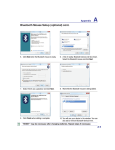
Bluetooth Mouse Setup (optional) ..................................................................... A-4
Operating System and Software............................................................................. A-6
System BIOS Settings ....................................................................................... A-7
Common Problems and Solutions ..................................................................... A-9
Glossary ............................................................................................................... A-12
Declarations and Safety Statements .................................................................... A-16
Notebook PC Information ..................................................................................... A-26
3
Contents
4
1. Introducing the Notebook PC
About This User’s Manual
Notes For This Manual
Safety Precautions
Preparing your Notebook PC
There may be differences between your Notebook PC and the drawings shown in this
manual. Please accept your Notebook PC as being correct.
Photos and icons in this manual are used for artistic purposes only and do not show
what is actually used in the product itself.
5
1
Introducing the Notebook PC
About This User’s Manual
You are reading the Notebook PC User’s Manual. This User’s Manual provides information on the various components in the Notebook PC and how to use them. The following
are major sections of this User’s Manuals:
1. Introducing the Notebook PC
Introduces you to the Notebook PC and this User’s Manual.
2. Knowing the Parts
Gives you information on the Notebook PC’s components.
3. Getting Started
Gives you information on getting started with the Notebook PC.
4. Using the Notebook PC
Gives you information on using the Notebook PC’s components.
5. Appendix
Introduces you to optional accessories and gives additional information.
Notes For This Manual
A few notes and warnings in bold are used throughout this guide that you should be aware of in order
to complete certain tasks safely and completely. These notes have different degrees of importance as
described below:
NOTE: Tips and information for special situations.
TIP: Tips and useful information for completing tasks.
IMPORTANT! Vital information that must be followed to prevent damage to data, components, or persons.
WARNING! Important information that must be followed for safe operation.
< > Text enclosed in < > or [ ] represents a key on the keyboard; do not actually type the
[ ] < > or [ ] and the enclosed letters.
6
1
Introducing the Notebook PC
Safety Precautions
The following safety precautions will increase the life of the Notebook PC. Follow all precautions and
LQVWUXFWLRQV([FHSWDVGHVFULEHGLQWKLVPDQXDOUHIHUDOOVHUYLFLQJWRTXDOLÀHGSHUVRQQHO'RQRWXVH
GDPDJHGSRZHUFRUGVDFFHVVRULHVRURWKHUSHULSKHUDOV'RQRWXVHVWURQJVROYHQWVVXFKDVWKLQQHUV
benzene, or other chemicals on or near the surface.
IMPORTANT! Disconnect the AC power and remove the battery pack(s) before cleaning. Wipe the Notebook PC using a clean cellulose sponge or chamois cloth dampened
with a solution of nonabrasive detergent and a few drops of warm water and remove
any extra moisture with a dry cloth.
DO NOT place on uneven or unstable
work surfaces. Seek servicing if the
casing has been damaged.
DO NOT place or drop objects on top
and do not shove any foreign objects
into the Notebook PC.
DO NOT press or touch the display
SDQHO 'R QRW SODFH WRJHWKHU ZLWK
small items that may scratch or enter
the Notebook PC.
DO NOT expose to strong magnetic
RUHOHFWULFDOÀHOGV
DO NOT expose to dirty or dusty environments. DO NOT operate during
a gas leak.
DO NOT expose to or use near liquids,
rain, or moisture. DO NOT use the
modem during an electrical storm.
DO NOT leave the Notebook PC on
your lap or any part of the body in
order to prevent discomfort or injury
from heat exposure.
Battery safety warning:
DO NOT WKURZWKHEDWWHU\LQÀUH
DO NOT short circuit the contacts.
DO NOT disassemble the battery.
SAFE TEMP: This Notebook PC
should only be used in environments
with ambient temperatures between
5°C (41°F) and 35°C (95°F)
INPUT RATING: Refer to the rating
label on the bottom of the Notebook
PC and be sure that your power adapter
complies with the rating.
DO NOT throw the Notebook PC
in municipal waste. Check local
regulations for disposal of electronic
products.
DO NOT carry or cover a Notebook
PC that is powered ON with any materials that will reduce air circulation
such as a carrying bag.
7
1
Introducing the Notebook PC
Transportation Precautions
To prepare the Notebook PC for transport, you should turn it OFF and disconnect all external peripherals to prevent damage to the connectors. The hard disk drive’s head retracts when the power is turned
OFF to prevent scratching of the hard disk surface during transport. Therefore, you should not transport
the Notebook PC while the power is still ON. Close the display panel and check that it is latched securely
in the closed position to protect the keyboard and display panel.
CAUTION! The Notebook PC’s surface is easily dulled if not properly cared for. Be
careful not to rub or scrape the Notebook PC surfaces.
Cover Your Notebook PC
Purchase a carrying bag to protect the Notebook PC from dirt, water, shock, and scratches.
Charge Your Batteries
If you intend to use battery power, be sure to fully charge your battery pack and any optional battery
packs before going on long trips. Remember that the power adapter charges the battery pack as long as
it is plugged into the computer and an AC power source. Be aware that it takes much longer to charge
the battery pack when the Notebook PC is in use.
Airplane Precautions
Contact your airline if you want to use the Notebook PC on the airplane. Most airlines will have restrictions for using electronic devices. Most airlines will allow electronic use only between and not during
takeoffs and landings.
CAUTION! There are three main types of airport security devices: X-ray machines
(used on items placed on conveyor belts), magnetic detectors (used on people walking
through security checks), and magnetic wands (hand-held devices used on people or
individual items). You can send your Notebook PC and diskettes through airport X-ray
machines. However, it is recommended that you do not send your Notebook PC or
diskettes through airport magnetic detectors or expose them to magnetic wands.
8
1
Introducing the Notebook PC
Preparing your Notebook PC
These are only quick instructions for using your Notebook PC. Read the later pages for detailed information on using your Notebook PC.
1. Install the battery pack
2. Connect the AC Power Adapter
3
2
3
2
1
1
3. Open the Display Panel
4. Turn ON the Notebook PC
PIXELS
AF2.0 MEGA
IMPORTANT! When opening, do not force
the display panel down to the table or else
the hinges may break! Never lift the Notebook PC by the display panel!
The power switch turns ON and OFF the Notebook
PC or putting the Notebook PC into sleep or hibernation modes. Actual behavior of the power switch
can be customized in Windows Control Panel >
Power Options > System Settings.
9
1
10
Introducing the Notebook PC
2. Knowing the Parts
Basic sides of the Notebook PC
There may be differences between your Notebook PC and the drawings shown in this
manual. Please accept your Notebook PC as being correct.
Photos and icons in this manual are used for artistic purposes only and do not show
what is actually used in the product itself.
11
2
Knowing the Parts
Top Side
Refer to the illustration below to identify the components on this side of the Notebook PC.
The keyboard will be different for each territory.
1
2
PIXELS
AF2.0 MEGA
3
4
5
6
Esc
F1
~
F2
F3
F4
F5
F6
!
@
#
$
%
1
2
3
4
5
Q
Tab
W
F8
F9
F10
7
T
8
7
D
F
U
Y
G
H
5
X
Z
Shift
C
V
B
N
Del
SysRq
Pause
Break
7
Backspace
Home
P
6
K
1
Ins
Prt Sc
Num Lk
Scr Lk
0
9
O
I
J
F12
)
9
8
4
S
A
Caps
Lock
F11
(
&
6
R
E
F7
{
}
[
]
L
PgUp
Enter
8
PgDn
3
2
?
M
Shift
End
0
Fn
Ctrl
Alt
Alt
Ctrl
9
10
11
12
12
Knowing the Parts
1
2
Camera Indicator
The camera indicator shows when the built-in camera is in use. The camera may be auto-activated
by supported software.
2
Multi-Position Camera (on selected models)
The built-in camera allows picture taking or video recording. Can be
used with video conferencing and other interactive applications. Front
CAUTION: The lens can be adjusted facing forward or facing backward but
WKHOHQVFDQRQO\ÁLSWKURXJKWKHERWWRP'RQRWURWDWHWKHOHQVXSZDUGSDVWGHJUHHV
3
Back
Array Microphone (on selected models)
The built-in array microphone is more clear and echo-free compared with traditional single microphones and can be used for video conferencing, voice narrations, audio recordings, and multimedia
applications.
4
Display Panel
5
Status Indicators (top)
7KH1RWHERRN3&XVHVDQDFWLYHPDWUL[7)7/&'ZKLFKSURYLGHVH[FHOOHQWYLHZLQJOLNH
WKDWRIGHVNWRSPRQLWRUV8QOLNHWUDGLWLRQDOGHVNWRSPRQLWRUVWKH/&'SDQHOGRHVQRWSURGXFHDQ\UDGLDWLRQRUÁLFNHULQJVRLWLVHDVLHURQWKHH\HV8VHDVRIWFORWKZLWKRXWFKHPLFDO
liquids (use plain water if necessary) to clean the display panel.
Status indicators represent various hardware/software conditions. See indicator details in section 3.
6
Power Switch
The power switch turns ON and OFF the Notebook PC or putting the Notebook PC into sleep
or hibernation modes. Actual behavior of the power switch can be customized in Windows
Control Panel “Power Options.”
7
Instant Keys
Instant keys allow you to launch frequently used applications with one push of a button.
'HWDLOVare described in section 3.
8
Audio Speaker System
The built-in stereo speaker system allows you to hear audio without additional attachments.
The multimedia sound system features an integrated digital audio controller that produces
rich, vibrant sound (results improved with external stereo headphones or speakers). Audio
features are software controlled.
9
Keyboard
The keyboard provides full-sized keys with comfortable travel (depth at which the keys
can be depressed) and palm rest for both hands. Two Windows function keys are provided
to help ease navigation in the Windows operating system.
13
2
Knowing the Parts
Touchpad and Buttons
10
The touchpad with its buttons is a pointing device that provides the same functions as a desktop mouse. A software-controlled scrolling function is available after setting up the included
touchpad utility to allow easy Windows or web navigation.
Fingerprint Scanner (on selected models)
11
7KHEXLOWLQÀQJHUSULQWVFDQQHUDOORZVXVHRIVHFXULW\VRIWZDUHXVLQJ\RXUÀQJHUSULQWDV
\RXULGHQWLÀFDWLRQNH\
12
Status Indicators (front)
Status indicators represent various hardware/software conditions. See indicator details in section 3.
14
Knowing the Parts
2
Bottom Side
Refer to the illustration below to identify the components on this side of the Notebook PC.
The bottom side may vary in appearance depending on model.
The battery pack size will vary depending on model.
1
2
3
4
5
6
WARNING! The bottom of the Notebook PC can get very hot. Be careful when handling
the Notebook PC while it is in operation or recently been in operation. High temperatures are normal during charging or operation. Do not use on soft surfaces such as
beds or sofas which may block the vents. DO NOT PUT THE NOTEBOOK PC ON YOUR
LAP OR OTHER PARTS OF THE BODY TO AVOID INJURY FROM THE HEAT.
15
2
1
Knowing the Parts
Battery Pack
The battery pack is automatically charged when the Notebook PC is connected to an AC power source
and maintains power to the Notebook PC when AC power is not connected. This allows use when moving
WHPSRUDULO\EHWZHHQORFDWLRQV%DWWHU\WLPHYDULHVE\XVDJHDQGE\WKHVSHFLÀFDWLRQVIRUWKLV1RWHERRN
PC. The battery pack cannot be disassembled and must be purchased as a single unit.
Battery Lock - Manual
2
The manual battery lock is used to keep the battery pack secured. Move the manual lock to the
unlocked position to insert or remove the battery pack. Move the manual lock to the locked position after inserting the battery pack.
Battery Lock - Spring
3
The spring battery lock is used to keep the battery pack secured. When the battery pack is inserted, it will
automatically lock. To remove the battery pack, this spring lock must be held in the unlocked position.
4
Memory (RAM) Compartment
The memory compartment provides expansion capabilities for additional memory. Additional
memory will increase application performance by decreasing hard disk access. The BIOS auWRPDWLFDOO\GHWHFWVWKHDPRXQWRIPHPRU\LQWKHV\VWHPDQGFRQÀJXUHVDFFRUGLQJO\7KHUHLV
no hardware or software (including BIOS) setup required after the memory is installed. Visit an
authorized service center or retailer for information on memory upgrades for your Notebook PC. Only purchase expansion modules from authorized retailers of this Notebook PC to ensure maximum compatibility and reliability.
Central Processor Unit (CPU) Compartment
Some Notebook PC models feature a socketed-processor design to allow upgrading to faster
processors in the future. Some models feature a ULV design for compactness and may not
be upgraded. Visit an authorized service center or retailer for information on upgrades.
WARNING! End-user removal of the CPU or hard disk drive will void the warranty.
Shutdown Button (Emergency)
5
In case your operating system cannot properly turn OFF or restart, the shutdown button can
be pressed with a straightened paper clip to shutdown the Notebook PC.
6
Hard Disk Drive Compartment
The hard disk drive is secured in a compartment. Visit an authorized service center or retailer for
information on hard disk drive upgrades for your Notebook PC. Only purchase hard disk drives
from authorized retailers of this Notebook PC to ensure maximum compatibility and reliability.
16
Knowing the Parts
2
Right Side
Refer to the illustration below to identify the components on this side of the Notebook PC. The components vary by model.
1
1
2
3 4
5
6
Optical Drive
The Notebook PC comes in various models with different optical drives. The Notebook
3&·VRSWLFDOGULYHPD\VXSSRUWFRPSDFWGLVFV&'DQGRUGLJLWDOYLGHRGLVFV'9'DQG
PD\KDYHUHFRUGDEOH5RUUHZULWDEOH5:FDSDELOLWLHV6HHWKHPDUNHWLQJVSHFLÀFDtions for details on each model.
2
Optical Drive Activity Indicator (location varies by model)
The optical drive activity indicator shows when data is being transferred by the optical disk
drive. This indicator will light in proportion to the data size transferred.
3
Optical Drive Electronic Eject
The optical drive eject has an electronic eject button for opening the tray. You can also eject
the optical drive tray through any software player or by right clicking the optical drive in
Windows “Computer” and selecting Eject.
4
Optical Drive Emergency Eject (location varies by model)
The emergency eject is used to eject the optical drive tray in case the electronic eject does
QRWZRUN'RQRWXVHWKHHPHUJHQF\HMHFWLQSODFHRIWKHHOHFWURQLFHMHFW
5
2.0
USB Port (2.0/1.1)
The USB (Universal Serial Bus) port is compatible with USB 2.0 or USB 1.1 devices such as
keyboards, pointing devices, cameras, hard disk drives, printers, and scanners connected in a
series up to 12Mbits/sec (USB 1.1) and 480Mbits/sec (USB 2.0). USB allows many devices to
run simultaneously on a single computer, with some peripherals acting as additional plug-in sites or
hubs. USB supports hot-swapping of devices so that most peripherals can be connected or disconnected
without restarting the computer.
17
2
Knowing the Parts
Modem Port
6
The RJ-11 modem port with two pins is smaller than the RJ-45 LAN port and supports
a standard telephone cable. The internal modem supports up to 56K V.90 transfers. The
built-in connector allows convenient use without additional adapters.
IMPORTANT! The built-in modem does not support the voltage used in digital
phone systems. Do not connect the modem port to a digital phone system or
else damage will occur to the Notebook PC.
Left Side
Refer to the illustration below to identify the components on this side of the Notebook PC.
1
1
2.0
2
2
HDMI
E-SATA
3
4
5
6
USB Port (2.0/1.1)
The USB (Universal Serial Bus) port is compatible with USB 2.0 or USB 1.1 devices such as
keyboards, pointing devices, cameras, hard disk drives, printers, and scanners connected in a
series up to 12Mbits/sec (USB 1.1) and 480Mbits/sec (USB 2.0). USB allows many devices to
run simultaneously on a single computer, with some peripherals acting as additional plug-in sites or
hubs. USB supports hot-swapping of devices so that most peripherals can be connected or disconnected
without restarting the computer.
Air Vents
The air vents allow cool air to enter and warm air to exit the Notebook PC.
IMPORTANT! Make sure that paper, books, clothing, cables, or other objects
do not block any of the air vents or else overheating may occur.
18
Knowing the Parts
3
HDMI
4
E-SATA
2
HDMI Port (on selected models)
+'0,+LJK'HÀQLWLRQ0XOWLPHGLD,QWHUIDFHLVDQXQFRPSUHVVHGDOOGLJLWDODXGLR
YLGHRLQWHUIDFHEHWZHHQDQ\DXGLRYLGHRVRXUFHVXFKDVDVHWWRSER['9'SOD\HU
and A/V receiver and an audio and/or video monitor, such as a digital television
'79 6XSSRUWV VWDQGDUG HQKDQFHG RU KLJKGHÀQLWLRQ YLGHR SOXV PXOWLFKDQQHO
GLJLWDODXGLRRQDVLQJOHFDEOH,WWUDQVPLWVDOO$76&+'79VWDQGDUGVDQGVXSSRUWV
8-channel digital audio, with bandwidth to spare to accommodate future enhancements or requirements.
E-SATA Port (on selected models)
External SATA or eSATA allows external connection of Serial-ATA devices originally designed for use
inside the computer. It is up to six times faster than existing USB 2.0 and 1394 for external storage solutions and is also hot pluggable.
5
TV-Out Port (on selected models)
The TV-Out port is an S-Video connector that allows routing the Notebook PC’s display
to a television or video projection device. You can choose between simultaneously or
single display. Use an S-Video cable (not provided) for high quality displays or use the
provided RCA to S-Video adapter for standard video devices. This port supports both
NTSC and PAL formats.
6
ExpressCard Slot
One 26pin Express card slot is available to support one ExpressCard/34mm or one
ExpressCard/54mm expansion card. This new interface is faster by using a serial bus
supporting USB 2.0 and PCI Express instead of the slower parallel bus used in the PC
card slot. (Not compatible with previous PCMCIA cards.)
19
2
Knowing the Parts
Front Side
Refer to the illustration below to identify the components on this side of the Notebook PC.
1
1
2
3
4
5
Flash Memory Slot
Normally an external memory card reader must be purchased separately in order to use
memory cards from devices such as digital cameras, MP3 players, mobile phones, and
3'$V7KLV1RWHERRN3&KDVDEXLOWLQKLJKVSHHGPHPRU\FDUGUHDGHUWKDWFDQFRQYHQLHQWO\
UHDGIURPDQGZULWHWRPDQ\ÁDVKPHPRU\FDUGVDVPHQWLRQHGODWHULQWKLVPDQXDO
IEEE1394 Port (on selected models)
2
IEEE1394 is a high speed serial bus like SCSI but has simple connections and hotplugging capabilities like USB. The interface IEEE1394 has a bandwidth of 100-400
Mbits/sec and can handle up to 63 units on the same bus. IEEE1394 is also used in
KLJKHQGGLJLWDOHTXLSPHQWDQGVKRXOGEHPDUNHG´'9µIRU'LJLWDO9LGHRSRUW
3
Combo
SPDIF Output Jack
7KLVMDFNSURYLGHVFRQQHFWLRQWR63',)6RQ\3KLOLSV'LJLWDO,QWHUIDFHFRPSOLDQWGHYLFHVIRUGLJLWDODXGLRRXWSXW8VHWKLVIHDWXUHWRWXUQWKH1RWHERRN3&LQWRDKLÀKRPH
entertainment system.
Headphone Output Jack
The stereo headphone jack (1/8 inch) is used to connect the Notebook PC’s audio out signal to
DPSOLÀHGVSHDNHUVRUKHDGSKRQHV8VLQJWKLVMDFNDXWRPDWLFDOO\GLVDEOHVWKHEXLOWLQVSHDNHUV
Microphone Input Jack
4
The mono microphone jack (1/8 inch) can be used to connect an external microphone or output
signals from audio devices. Using this jack automatically disables the built-in microphone. Use
this feature for video conferencing, voice narrations, or simple audio recordings.
5
Audio Input Jack
The stereo input jack (1/8 inch) can be used to connect a stereo audio source to the Notebook PC.
This feature is used mainly to add audio to multimedia applications.
20