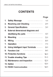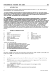
1
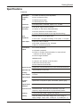
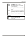
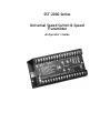
SST-2000 Series Universal Speed Switch & Speed Transmitter An Operator’s Guide Copyright Specifications and information herein are subject to change without notice. Dynalco Controls reserves the right to make changes to the equipment described herein to improve function or design. Although the information contained in this manual has been carefully reviewed and is believed to be reliable, Dynalco Controls does not assume any liability for special, indirect, incidental, or consequential damages arising out of the application or use of the equipment described herein. Warranty is limited and cannot exceed the price paid for the product upon which the warranty is based. Copyright 2001. All rights reserved. Trademarks SST-2000A/H, SST-2200A, SST-2400H are trademarks of Dynalco Controls. Dynalco Controls 3690 N.W. 53rd Street, Fort Lauderdale, FL 33309 U.S.A. ( (954) 739-4300 Fax (954) 484-3376 www.dynalco.com • [email protected] Printed in U.S.A. ii Contents Chapter 1 Getting Started 1 About your speed switch . . . . . . . . . . . . . . . . . . . . . . . . . . . . . . . . . . . . . . . . 2 Models. . . . . . . . . . . . . . . . . . . . . . . . . . . . . . . . . . . . . . . . . . . . . . . . . . . . . . 4 Features . . . . . . . . . . . . . . . . . . . . . . . . . . . . . . . . . . . . . . . . . . . . . . . . . . . . . 4 Specifications . . . . . . . . . . . . . . . . . . . . . . . . . . . . . . . . . . . . . . . . . . . . . . . . . 5 Chapter 2 Installing the SST-2000A/H 9 Mounting the unit . . . . . . . . . . . . . . . . . . . . . . . . . . . . . . . . . . . . . . . . . . . . 10 About Electrical Connections . . . . . . . . . . . . . . . . . . . . . . . . . . . . . . . . . . . 10 Connecting Signal Inputs. . . . . . . . . . . . . . . . . . . . . . . . . . . . . . . . . . . . . . . 11 Chapter 3 Powering External Devices 13 Powering an SPD-100, SPD-700, or other frequency instruments . . . . . . . . 14 Using DPM-105 meters as external speed indicators . . . . . . . . . . . . . . . . . . 14 Powering Zero Velocity Pickups and Other Loads . . . . . . . . . . . . . . . . . . . 16 Driving an SPV-200 Solenoid Pneumatic Valve . . . . . . . . . . . . . . . . . . . . . 17 Chapter 4 Calibrating the Speed Switch 19 Locating the programming switch instructions . . . . . . . . . . . . . . . . . . . . . . 20 Changing the full-scale input frequency range . . . . . . . . . . . . . . . . . . . . . . . 21 Input frequency range less than 80 Hz full-scale . . . . . . . . . . . . . . . . . . . . . . 21 Input frequency range greater than 20,000 Hz full-scale . . . . . . . . . . . . . . . . 21 Calibrating the SST-2000A/H . . . . . . . . . . . . . . . . . . . . . . . . . . . . . . . . . . . 22 Calibrating the 4-20 mA Proportional Output . . . . . . . . . . . . . . . . . . . . . . . 24 Programming Set Points and Relays . . . . . . . . . . . . . . . . . . . . . . . . . . . . . . 25 Adjusting Signal Sensitivity . . . . . . . . . . . . . . . . . . . . . . . . . . . . . . . . . . . . . 27 Response Time . . . . . . . . . . . . . . . . . . . . . . . . . . . . . . . . . . . . . . . . . . . . . . 28 Adjusting Individual Set Points . . . . . . . . . . . . . . . . . . . . . . . . . . . . . . . . . . 28 Verifying Set Point Values . . . . . . . . . . . . . . . . . . . . . . . . . . . . . . . . . . . . . . 31 Adjusting Set Point Values . . . . . . . . . . . . . . . . . . . . . . . . . . . . . . . . . . . . . 32 iii Chapter 1 Getting Started Chapter 1 About your speed switch WARNING When the SST-2000A/H Series Speed Switch/Transmitter is used as the primary overspeed shutdown device, it must be tested regularly. The SST-2000A/H series is a speed switch and signal transmitter that provides alarm set points for over- and underspeed control for sequential, startup, and shutdown switching for: t engines t machines t I/P drivers t instrumentation t process control t recording t measurement How it works The SST-2000A/H accepts a full-scale frequency input value from 0–0.1 Hz (6 pulses per minute) to 0–50,000 Hz. Standard: 0–80 Hz to 0–20,000 Hz. Examples of input devices include: t passive or active magnetic pickups t shaft encoders t contact closures t flow meters t photocells The speed switch converts frequency input (speed, rate) into linear proportional dc outputs: t 0–1 mA (standard - meter out) t 4–20 mA (standard - proportional out) t 0–5 Vdc (switch selectable) t 0–10 Vdc (switch selectable) It provides 0, 2, or 4 relay trip set points (depending on the model) 2 Getting Started Physical Dimensions Fig. 1-1 Top and side view of the SST-2000A/H. Dimensions in inches and (centimeters). Special explosion proof housings kits (complete with mounting hardware) are also available. See XP rated housings on page 6. 3 Chapter 1 Models Model No. Of Set Points 3rd Party Certification(s) A series – standard relays SST-2000A 0 SST-2200A 2 SST-2400A 4 CSA: general certification LR 92270 ABS: type approval CE: 89/336/EEC, Light Industrial CE: 72/23/EEC, Low Voltage Directive H series – hermetically sealed relays SST-2000H 0 SST-2200H 2 SST-2400H 4 CSA: Class I, Div. 2, Grp. D, LR 45322* CE: 89/336/EEC, Light Industrial CE: 72/23/EEC, Low Voltage Directive * Approval contingent upon housing an SST-2000H series device in a CSA-certified enclosure. Features Signal Sources Field-programmable for: sensors, including contact closure input, magnetic pickups, ac generators, contact closures, photocells. Input Frequency t Full-scale values from 0–0.1 Hz (6 pulses/minute) to 0-20 kHz. Alarm Set Points 0 SST-2000A/H (when only proportional output is required) 2 SST-2200A/H 4 SST-2400A/H t Field-adjustable range and sensitivity control. Alarm Settings Alarms are field-configurable for overspeed, underspeed, energize, de-energize, latch, auto-reset. Alarm Disable Disable all alarms (for startup conditions and special functions) Alarm Reset t Momentarily reset all latched alarms t Permanently converts all latching alarms to auto-reset 4 Set Point Verification Integral VERIFY permits viewing and setting of set point value without actuating the relays. Requires an external meter. Proportional Outputs 0–1 mA and 4–20 mA (standard) Output Power Repeater output drives counters and self-powered tachometers. Regulated 14 Vdc output powers active pickups, accessories, and meters (e.g. DPM-105; MTH-103D; SPD-100L; LST-100L). Output Range Current source up to 50 mAdc output always included. 0–5 Vdc or 0–10 Vdc (field-selectable) Getting Started Specifications Electrical Input Signal Frequency Range t 0-20 kHz (standard) (field-adjustable) t 0-0.1 Hz (special order) t 0-80 Hz (special order) t 0-50K Hz (special order) Waveforms t Accepts pulsed, sinusoidal, square, TTL, or CMOS Input Signal Sensitivity t 25 mVrms (typical factory setting) t 5 mVrms to 100 mVrms (field-adjustable) t 50 Vrms (maximum for standard units) t 1.0 volt threshold (requires input signal desensitizing) Input Impedance t Nearly infinite at low signal levels Power Input t 115 Vac ±10%, 47-420 Hz t 10 kΩ (min.) at signals exceeding +15.0 V peak, –1.0 V peak t 22–30 Vdc, maximum 5 W or 150 mAdc t 220 Vac, 50/60 Hz (optional) Proportional Output t 0–1 mAdc (standard) t 4–20 mAdc (standard) t 0–5 Vdc or 0–10Vdc (field-selectable; for external load resistance of 20 kΩ or higher) t Custom ranges available MAXIMUM LOAD t 1 kΩ with 115/ 220 Vac or 30 Vdc power t 750 ohms with 22 Vdc power t linear between 22 and 30 Vdc Output Current Independent of load resistance up to the rated load resistance Span/zero adj. ±5% (minimum) of fuIl-scale Auxiliary Meter Output Proportional 0–1 mAdc, filtered, for meter or recorder loads up to 750 Ω. Supply Output Regulated +14 Vdc ±5%; 40 mAdc (maximum load) Repeater Output Square wave 14 V peak-to-peak, zero based, positive going Output Ripple and Noise 0.1% of full-scale maximum over 10% to 100% of full-scale. Response Time 150 milliseconds, 10% to 90% rise (standard). Full-scale frequency ranges below 80 Hz are proportionally slower. Linearity 0.1% of full-scale (0.05%, typical), all outputs. Stability Less than 0.05% of full-scale change with a 10% change in supply voltage. Temp. coeff. ±0.01% per °F (±0.018% per °C) 5 Chapter 1 Relays Logic Field-programmable by switches for: t overspeed/underspeed t energize/de-energize t latch/auto-reset t SPST/DPDT (2 DPDT set points maximum) A Series Contact Rating t 6.0 A @ 28 Vdc or 115 Vac (resistive) t 2.0 A @ 220 Vac t 1.0 A into 500 mH for up to 100,000 cycles t SPDT* *For DPDT, Relays 1 & 3 and 2 & 4 work together as separate DPDT trips. H Series Contact Rating t 5 A (resistive) @ 24 Vdc t 1.0 A @ 120 Vac t 0.5 A @ 220 Vac t SPDT* *For DPDT, Relays 1 & 3 and 2 & 4 work together as separate DPDT trips. Alarm Set Points t Adjustable, 25-turn cermet potentiometers Hysteresis t 1% of full-scale frequency Isolation Transformer t Optional. Isolates the transmitter input from the probe or sensor. XP Rated Housings (optional) ENC-6210 XP Cast Housing: 8”H x 10”W x 5” D; 100’s window + P-button UL/CSA Class I, Groups C,D Class II, Groups E,F,G NEMA 3,4 ENC-6311 XP Cast Housing: 8”H x 10”W x 5” D; 100’s window UL/CSA Class I, Groups B,C, D Class II, Groups E,F,G NEMA 3,4 ENC-3000 Sheet Meta:l 6”H x 9”W x 4” D; NEMA 1; No Window ENC-4000 Sheet Meta:l 8”H x 10”W x 4” D; NEMA 12; No Window ENC-5000 XP Cast Housing: 7”H x 9”W x 5”D; No Window UL/CSA Class I, Groups C,D; Class II, Groups E,F,G 6 Getting Started Options Enclosures XP and NEMA rated enclosures are available. Open Pickup Relay 1 switches in the event of an open or disconnected magnetic pickup. Relay 1 will still react when its set point is traversed (field-configurable). NOTE: Not available with signal isolation transformer option. Pneumatic Trip Pulses relay 1 for 100 milliseconds Trips Dynalco SPV-200 Solenoid Pneumatic Valve on overspeed (optional) Underspeed Class “C” Logic Arms relay 2 as set point 2 is traversed on increasing speed. Pulses relay 2 as set point 2 is traversed on decreasing speed. Use for tripping the pneumatic SPV-200 on underspeed or for general underspeed electrical shutdown. Expanded Scale Input Provides full meter output, full proportional output, and full set point range over a limited input range e.g. 0–1 mA and 4–20 mA over 800–1000 Hz input frequency. Environmental Temperature Range –40°F to +160°F (–40°C to +71°C ) operating Weight 2.6 lbs (1.17 kg) –40°F to + 180°F (–40°C to +82°C) storage 7 Chapter 2 Installing the SST-2000A/H Chapter 2 Mounting the unit The SST-2000A/H is installed using standard hand tools. It is generally mounted in a panel or enclosure using standard practices. About Electrical Connections Internal Commons, Isolation WARNING: AVOID DAMAGE WHEN DC-POWERED Install a current loop isolator between the 4–20mA output and the load if the load does not reference the same common as the SST-2000A/H. Signal input (low side, terminal 6) is common to the auxiliary output (low side, terminal 7), to the dc supply (terminal 4), and to the main proportional output low side (terminal 9). Relay contacts are always isolated When powered with ac: all circuitry is isolated from the power line by the built-in supply transformer When powered with dc: the transmitter output is not isolated from the dc power source. Any load driven by the transmitter (i.e. recorder, controller, etc.) must have the same common as the negative side of the dc supply. Install a current loop isolator between the 4–20mA output and the load if the load does not reference the same common as the SST-2000. Fig. 2-1 Electrical Connection Drawing. Use shielded cable: connect ungrounded shield to terminal 4. Route power line and relay connections separate from signal meter and reset lines to prevent electrical noise interference. Terminals 4, 6, 7, and 9 are internally tied together to circuit common unless unit has signal isolation transformer. In that case, terminal 6 is isolated. 10 Installing the SST-2000A/H Connecting Signal Inputs Connecting a PG-278 Pulser Connect signal source Common to terminal 6 on the SST-2000A/H. Connect signal HI to terminals on the SST-2000A/H. Fig. 2-2 Connecting a PG-278 Pulser to the SST-2000A/H. Terminals 11 and 30 on the SST-2000A/H are jumpered to create a one volt threshold. 11 Chapter 3 Powering External Devices Chapter 3 Powering an SPD-100, SPD-700, or other frequency instruments The SST-2000A/H has a repeater output that can be used to power external frequency instruments. A square wave (14-volt peak-to-peak, zero-based, positive-going) is brought out at terminals 29 and 4 (common) to drive self-powered digital tachometers such as the SPD-100, SPD-700, and MTH-103D, or to use as a conditioned high level signal source into counters or other instruments. The frequency of the signal is equal to that being applied at the signal input: terminals 5 (+) & 6 (–). This output has an internal resistance of 1 kΩ. Using DPM-105 meters as external speed indicators You can use the DPM-105 as an external indicator. You can connect one or more DPM-105 meters to your SST-2000A/H. The 0-1 mA meter output of the SST-2000A/H [terminals 7 (–) and 8 (+)] is factory-calibrated into an external load of 40 Ω. The load resistance of the DPM-105 is 95 Ω. Connecting one DPM-105 1 On the DPM-105, retain the jumper across terminals 1 and 2. 2 Connect the meter as shown in Fig. 3-3. 3 Calibrate the SST-2000A/H. Fig. 3-3 Connecting one DPM-105 to the SST-2000A/H. t Keep the jumper between terminal 1 & 2 on the DPM-105 14 Powering External Devices t Confirm the meter is properly connected to the SST-2000A/H. t Use a frequency generator (e.g. F-16) to apply full-scale frequency to terminal 5 (HI) & 6 (COM) on the SST-2000A/H. Maximum signal input is 50 Vrms for a standard unit. t Adjust the METER CALIBRATE potentiometer on the SST-2000A/H for the appropriate full-scale reading on each DPM-105. t Use a DPM-105 data sheet, if necessary, to calibrate the DPM-105 meters. Connecting more than one DPM-105 1 Remove the jumper across terminals 1 and 2 on each DPM-105. 2 Connect the meters as shown in Fig. 3-4. 3 Calibrate the SST-2000A/H. Fig. 3-4 Connecting more than one DPM-105 to the SST-2000A/H. t Confirm the meter is properly connected to the SST-2000A/H. t Apply full-scale frequency to terminal5 (HI) & 6 (COM) on the SST-2000A/H. Maximum signal input is 50 Vrms for a standard unit. t Adjust the ME TER CAL I BRATE po ten ti om e ter on the SST-2000A/H for the ap pro pri ate full -scale read ing on each DPM-105. t Use a DPM-105 data sheet, if necessary, to calibrate the DPM-105 meters. 15 Chapter 3 Powering Zero Velocity Pickups and Other Loads The regulated 14 Vdc supply brought out at terminals 11 (+) & 4 (–) has a capacity of 40 mA. This output can power zero velocity pickups (e.g. M928) and digital indicators like a DPM-105. 1 Connect the M928 pickup as indicated in Fig. 3-5. 2 Jumper terminals 11 and 30 to desensitize the input signal to a 1.0 V threshold. 3 Adjust signal sensitivity if necessary. See page 27 for instructions on how to adjust input sensitivity. Fig. 3-5 Jumper terminals 11 and 30 to desensitize the input signal circuit to a one-volt threshold. 16 Powering External Devices Driving an SPV-200 Solenoid Pneumatic Valve WARNING: TO AVOID SPV-200 COIL DAMAGE Use a current limiting resistor in series with the dc power source and the transferring relay contacts. The SPV -200 coil has a resistance of 50 Ω and requires 6 Vdc to trip. Switching the Regulated 14 Vdc Supply The regulated 14 Vdc supply at terminals 11 (+) & 4 (–) does not have the capacity to drive the SPV-200 continually. When the SST-2000A/H speed transmitter is supplied with the Pneumatic Trip Option for Overspeed, Relay 1 transfers for only 100 milliseconds on overspeed; the 14 volt supply can then be used with a series limiting resistor to power the pneumatic trip. Use a ¼ watt, 47–50 Ω resistor in series with the 14 volt supply. Fig. 3-6 Switching the regulated 14 Vdc supply. Switching 28 Vdc When switching 28 Vdc into the coil, use a 5–10 watt, 180 Ω resistor in series with the SPV-200 coil. Fig. 3-7 Switching the 28 Vdc supply. 17 Chapter 4 Calibrating the Speed Switch Chapter 4 Locating the programming switch instructions Fig. 4-8 A full description of the programming switches and controls is located under the top plate of the SST-2000A/H. 1 Use a no. 1 or no. 2 Phillips screwdriver to remove the top plate of the switch. 2 The underside of the plate contains instructions for how to: t latch set point relays on alarm t actuate relays on overspeed t actuate 2 relays simultaneously (as DPDT relay) t de-energize relays on alarm t change proportional output to 0–5 Vdc or 0–10 Vdc t recalibrate the full-scale input frequency range (switch A settings) 20 Calibrating the Speed Switch Changing the full-scale input frequency range You can set the standard full-scale frequency range from as low as 0–80 Hz to as high as 0–20 kHz. 1 Remove the top plate from the SST-2000A/H to reveal the “A” DIP switches. 2 Use Table 4-1, page 23, or the underside of the top plate (bottom of Fig. 4-9, page 22) to determine the correct DIP switch settings. 3 Calibrate the SST-2000A/H using the procedure on page 22. Input frequency range less than 80 Hz full-scale The full-scale frequency input range is usually set up at the factory when an SST-2000A/H is ordered. The SST-2000A/H can easily be field-modified for any standard full scale input frequency range from 0–80 Hz to 0–20,000 Hz using the procedure Recalibration of Full-Scale Input Frequency Range. Field-changing the SST-2000A/H to accept input frequencies less than 0-80 Hz full-scale is not recommended. Damage might result that could void the product warranty. Please contact the Dynalco Customer Service Department at (954) 739-4300 for guidance in arranging for a low input frequency range. Input frequency range greater than 20,000 Hz full-scale The full-scale frequency input range is usually set up at the factory when an SST-2000A/H is ordered. The SST-2000A/H can easily be field-modified for any standard full scale input frequency range from 0–80 Hz to 0–20,000 Hz using the procedure Recalibration of Full-Scale Input Frequency Range. Field-changing the SST-2000A/H to accept input frequencies greater than 0-20,000 Hz full-scale is not recommended. Damage might result that could void the product warranty. Please contact the Dynalco Customer Service Department at (954) 739-4300 for guidance in arranging for a high input frequency range. 21 Chapter 4 Calibrating the SST-2000A/H WARNING Calibrate the speed switch: • immediately after any contact change in Switch A • before adjusting set points or proportional output You must calibrate the SST-2000A/H if you have made a change in the full-scale frequency range (changed contacts to DIP switch A). 1 Disconnect any meter connected to terminals 7 & 8. Mark or position the wires so they can be correctly reattached later. 2 Connect a digital voltmeter across terminals 7(–) & 8 (+). 3 Connect a frequency generator (e.g. F-16) at terminals 5 (HI) & 6 (COM). Use the frequency generator to input the new full-scale frequency. 4 Adjust the FREQ RANGE TRIM potentiometer for 10.00 Vdc on the voltmeter. (See Fig. 4-9.) 5 Reattach the meter that is normally connected to terminals 7(–) & 8 (+). Observe polarity. Fig. 4-9 The contact arrangements for the full-scale frequency range switch (A) are on underside of the top plate. S.P. 2 S.P. 1 FR EQ. R AN GE TR IM METER CAL 8 7 6 5 FREQU EN CY RANGE SWITCH 4 3 2 AFTER SETTI NG R ANGE SWITCH “A”, TR IM FOR 10. 0V 1 AT OPEN TER MINA LS 8 & 7 AT A O F F FULL SC ALE FR EQUEN CY. SIGNAL SEN SI TIVITY 1,8: .08 - .1 ; 2,8: .1 - .13 ; 3,8: .13 - .17 4,8: .17 - .22 ; 5,8: .22 - .3 ; 6,8: .3 - .38 7,8: .38 - .5 ; 7,2,8: .48 - .63 1,4,7,8: .63 - .83 1, 2, 3, 5, 6, 8: .83 - 1.09 1: .86 - 1.12 ; 2: 1.1 - 1.4 ; 3: 1.4 - 1.9 4: 1.9 - 2.5 ; 5: 2.5 - 3.2 ; 6: 3.2 - 4.2 7: 4.2 - 5.5 ; 7,2: 5.3 - 6.9 ; 1, 4, 7: 6.9 - 9.1 1, 2, 3, 5, 6: 9.1 - 12 2, 3, 4, 6, 7: 12 - 15.5 1, 2, 3, 4, 5, 6, 7: 15.1 - 20 22 MAX Calibrating the Speed Switch Table 4-1 Table of full-scale frequency and the corresponding switch “A” ON settings. Freq. Range (in kHz) Switch A ON Positions Freq. Range (in Hz) 0.08 - 0.10 1, 8 80 - 100 0.10 - 0.13 2, 8 100 - 130 0.13 - 0.17 3, 8 130 - 170 0.17 - 0.22 4, 8 170 - 220 0.22 – 0.30 5, 8 220 - 300 0.30 - 0.38 6, 8 300 - 380 0.38 – 0.50 7, 8 380 - 500 0.48 – 0.63 7, 2, 8 480 - 630 0.63 – 0.83 1, 4, 7, 8 630 - 830 0.83 – 1.09 1, 2, 3, 5, 6, 8 830 - 1,090 0.86 – 1.12 1 860 - 1,120 1.10 – 1.40 2 1,100 - 1,400 1.40 – 1.90 3 1,400 - 1,900 1.90 – 2.50 4 1,900 - 2,500 2.50 – 3.20 5 2,500 - 3,200 3.20 – 4.20 6 3,200 - 4,200 4.20 – 5.50 7 4,200 - 5,500 5.30 – 6.90 7, 2 5,300 - 6,900 6.90 – 9.10 1, 4, 7 6,900 - 9,100 9.10 – 12.0 1, 2, 3, 5, 6 9,100 - 12,000 12.0 – 15.5 2, 3, 4, 6, 7 12,000 - 15,500 15.1 – 20.0 1, 2, 3, 4, 5, 6, 7 15,100 - 20,000 23 Chapter 4 Calibrating the 4-20 mA Proportional Output You must calibrate the speed switch if the standard proportional output of 4 to 20 mA is changed to : t 0–5 Vdc using switch C1, or t 0–10 Vdc using switch C2 To calibrate the new proportional output 1 Attach a digital voltmeter to terminals 9 (–) & 10 (+). 2 Apply 10% of the full-scale frequency to input terminals 5 (+), 6 (–). 3 Adjust the PROP OUT ZERO adjust potentiometer (See Fig. 4-10, below) to yield 10% of full-scale proportional output on the voltmeter. Fig. 4-10 The PROP OUT ZERO and PROP OUT SPAN adjustments are located in the upper right corner under the top plate of the SST-2000A/H. 4 Apply 100% of full-scale frequency to terminals 5 (+) & 6 (–). 5 Turn PROP OUT SPAN adjust potentiometer (See example below) to yield 100% of full-scale proportional output on the voltmeter . 6 Repeat steps 2, 3, 4, and 5 three or four times to assure accuracy. EXAMPLE: A unit calibrated for 0–500 Hz input is being recalibrated to 0-10 Vdc proportional output (from 4–20 mAdc proportional output). ♦ Apply 10% of full-scale (50 Hz) to terminals 5 (+) & 6 (–). ♦ Adjust PROP OUT SPAN adjust potentiometer to yield 1.000 Vdc on the voltmeter. ♦ Apply full-scale frequency (500 Hz) to terminals 5 (+) & 6 (–). ♦ Turn PROP OUT ZERO adjust potentiometer to yield 10.00 Vdc. ♦ Repeat 3 or 4 times for accuracy. 24 Calibrating the Speed Switch Programming Set Points and Relays Remove the top plate from the SST-2000A/H to reveal DIP switches B and C. Use DIP switches B and C to program relay set points to: t energize (OFF) / de-energize (ON) on alarm t non-latch (OFF) / latch (ON) on alarm t actuate SPST (OFF) / DPDT (ON) trip on alarm t change proportional voltage output Fig. 4-11 The DIP switch settings available to you depend on the model of speed switch you purchased: t SST-2400A/H series switches have four set point relay adjustments (DIP switches B and C). t SST-2200A/H series switches only have relays 1 and 2 (adjustable using DIP switch C). t SST-2000A/H switches have no set point relays. The underside of the top plate contains labels for each DIP switch setting. Resetting a latched relay To momentarily reset a latched relay, jumper terminals 32 and 7. 25 Chapter 4 Set points 3 & 4 and selecting DPDT trip WHEN ALL B SWITCHES ARE OFF t relays 3 and 4 are energized, underspeed t non-latching THE EFFECT OF TURNING B SWITCHES ON Turn on B to... B1 LATCH set point 3 on alarm B2 ACTUATE relay 4 simultaneously with relay 2, creating two Form C contacts for set point 2 (DPDT relay). B3 LATCH set point 4 on alarm B4 ACTUATE relay 3 simultaneously with relay 1, creating two Form C contacts for set point 1 (DPDT relay). B5 DE-ENERGIZE relay 3 on alarm B6 DE-ENERGIZE relay 4 on alarm B7 ACTUATE set point 4 on overspeed. B8 ACTUATE set point 3 on overspeed. t all relays are SPST EXAMPLE: To set relays 3 and 4 to actuate, de-energize, and latch on overspeed, turn on B1, B3, B5, B6, B7, and B8. Set points 1 & 2: 0–5 & 0–10 Vdc proportional output WHEN ALL C SWITCHES ARE OFF THE EFFECT OF TURNING C SWITCHES ON t the proportional Turn on C to... output is 4-20 mA t relays 1 and 2 are energized, underspeed t non-latched EXAMPLE: To change the proportional output to 0–10 Vdc, and set relay 2 to actuate, energize, and latch on overspeed, turn on C2, C6, and C7. 26 C1 Change proportional output to 0-5 Vdc*. Confirm C2 is OFF. C2 Changes proportional output to 0-10 Vdc*. Confirm C1 is OFF. C3 DE-ENERGIZE relay 2 on alarm. C4 ACTUATE relay 1 on overspeed, non-latch. C5 LATCH relay 1 on alarm. C6 LATCH relay 2 on alarm. C7 ACTUATE relay 2 on overspeed, non-latch. C8 DE-ENERGIZE relay 1 on alarm. * Requires recalibration. Calibrating the Speed Switch Adjusting Signal Sensitivity Desensitizing Standard Inputs Signal sensitivity is factory set to 25 mVrms (about 35 mV peak or 70 mV peak-to-peak) and satisfies most applications. Fig. 4-12 The signal sensitivity control is located under the A DIP switch. Higher sensitivities can be more vulnerable to noise. To raise sensitivity Turn the SIGNAL SENSITIVITY potentiometer (Fig. 4-12) clockwise. At full clockwise rotation, sensitivity is approximately 5 mVrms. To lower sensitivity Turn the SIGNAL SENSITIVITY potentiometer counterclockwise. At full counterclockwise rotation, the sensitivity is approximately 100 mVrms. Desensitizing Contact Closure Jumper terminals 30 and 11 to desensitize the unit to about 1 Vrms. Signal Sensitivity pot setting does not affect this procedure. Fig. 4-13 Jumper terminals 11 to 30 to desensitize the SST-2000A/H for contact closure input. 27 Chapter 4 Response Time Response time is the time required for the proportional outputs to change from 10% to 90% of the maximum calibrated value for an instantaneous step change of the input frequency. Response time affects the transfer speed of the relays. RELAY RESPONSE Contact Dynalco if you need a different relay response time. Standard response time is 150 milliseconds over all standard input frequency ranges: 0-80 Hz full-scale to 0-20,000 Hz full-scale. Response times below 80 Hz full-scale are proportionally slower. While other response times can be provided, field modification is not recommended since damage might result that could void the product warranty. Contact Dynalco if you need a different relay response time. Adjusting Individual Set Points 1 Verify that the SST-2000A/H is calibrated to the correct full-scale frequency range (see page 22). 2 Tools required: Either a very thin-bladed screwdriver or a transformer alignment tool; signal generator (Dynalco’s F-16 or equivalent). 3 Provide a signal source. Use an F-16 signal generator or similar zero-crossing signal source, or use the frequency signal generated by the magnetic pickup on the engine. 4 Apply a frequency signal to terminals 5 & 6. This frequency input should equal the target RPM value of the set point being adjusted. Setpoint Frequency (Hz) = RPM x No. of teeth or holes on flywheel 60 For example: Calculate the set point frequency for a gear with 72 teeth rotating at 800 RPM. Frequency (Hz) = (800 ) × (72 teeth) = 960 Hz (to terminals 5 & 6) 60 Alternate Method 1: Adjusting set points while the engine is not running Use a signal generator to adjust individual set points when the engine is not operating and if you do not have an analog RPM meter. 1 28 Disconnect the wires to terminals 5 & 6. Mark or position the wires to assure correct replacement. Calibrating the Speed Switch 2 Apply the calculated set point frequency to terminals 5 (HI) & 6 (COM). 3 Apply operating power to the SST-2000A/H. See lid of your SST-2000A/H or spec sheet for power choices. 4 Select the appropriate set point trim pot. 5 Turn the pot: t Counterclockwise to lower the set point value (reduce the speed at which the set point relay will trip ). t Clockwise to raise the set point value (increase the speed at which the set point relay will trip). 6 Turn the pot slowly so as not to pass the target set point by a large amount. The pot has fine resolution, so a large change in set point value may take several turns. 7 While adjusting the pot, listen for the relay to trip at the set point. You can hear a distinct click when the contacts transfer. If high ambient noise makes it impossible to hear the relay click: use an ohmmeter as described in Alternate Method 2, below. 8 Fine tune the adjustment: 9 10 t After the relay trips, slowly REVERSE the adjustment of the set point pot until the relay again trips. t Again, slowly turn the pot FORWARD until the relay trips. Reattach the wires to terminals 5 (HI) & 6 (COM). Observe polarity. Repeat the above procedure for other set points to be changed. Alternate Method 2: Adjusting Individual Set Points While The Engine Is Operating A non-critical overspeed value is one that will not stress the engine. Use Alternate Method 3 to adjust set points while the engine is operating at a non-critical speed. NOTE: when the set point value is reached the relay will cause an engine shutdown or activate whatever is connected to that relay. A critical overspeed is typically the actual engine shutdown overspeed; running WARNING: DO NOT RUN AT OVERSPEED Use Alternate Method 3 to adjust set points while the engine is operating at NON-CRITICAL speed only. the engine at this speed is generally not desired. Use Alternate Method 1 if you cannot guarantee engine overspeed. 1 Run the engine at the desired speed using: 29 Chapter 4 t an RPM indicator/tachometer operating from one of the proportional outputs of the SST-2000A/H: t an independent meter mounted elsewhere on or near the engine. 2 Wait for the RPM to stabilize. 3 When RPM is stable, select the appropriate set point trim pot . 4 Follow the procedure in Alternate Method 1: steps 1-10. Alternate Method 3: Adjusting individual set points in high noise areas If high ambient noise makes it impossible to hear the relay click: 1 Disconnect the wire from: t the center post of the SST-2000A/H set point relay being adjusted. t either one of the other two contacts on the same relay. [Mark the wires or position them so they can be correctly reattached.] 30 2 Connect an ohmmeter to the center terminal of this relay and to either one of the other terminals of this relay. [If adjusting Relay 1, connect the ohmmeter to terminals 18 & 17 or 18 & 19.] The ohmmeter will indicate either a short or an open condition depending on which terminals are chosen. 3 Adjust the relay as outlined in Method 1: 1-10. When the relay trips, the ohmmeter will show a short or an open, opposite to the indication it had before the relay tripped. 4 Reattach the wires to the relays. 5 Repeat the above procedure for other set points to be changed. Calibrating the Speed Switch Verifying Set Point Values You can view and adjust the set point values without having to run the engine. NOTE: The SST-2000A/H (no set points) does not have set points. 1 The temporary jumper does not interfere with the normal operation of any relays. The 4–20 mA proportional output (terminals 9 & 10) is NOT affected by this procedure. The 14 Vdc pulsed output is not affected by this procedure. Jumper terminal 16 with the terminal that corresponds with the set point you want to view (for SST02200A/H and SST-2400A/H): t Set point 1: jumper 16 to 12 t Set point 2: jumper 16 to 13 t Set point 3: jumper 16 to 14 t Set point 4: jumper 16 to 15 2 When you jumper the two terminals, the 0–1 mA output meter connected to terminals 7 and 8 disconnects and displays the RPM (frequency, rate, etc.) value at that set point. 3 When the jumpers are removed, the meter switches back to its normal operation. 1 INPUT POWER 24 VDC 2 + - (Shown is the procedure for verifying Set point 1.) PROPORTIONAL MAIN OUTPUT +14 VDC OUTPUT 3 4 20 21 22 METER CALIBRATE + 7 8 23 24 + 9 10 25 26 + SETPOINT 1 SETPOINT 2 SETPOINT 3 SETPOINT 4 VERIFY SETPOINTS 18 19 5 6 SIGNAL INPUT Fig. 4-14 Verify the set point values and view the RPM (frequency, rate, etc.) on the 0–1 mA output meter connected to terminals 7 & 8. 17 11 12 13 14 15 1 2 27 28 3 4 SETPOINT ADJUSTMENTS 29 30 31 32 16 31 Chapter 4 Adjusting Set Point Values WARNING You can adjust set points while the engine or other device is operating. However, if you adjust a set point relay to a value lower than the current operating speed, the relay will trip. You will need a 0–1 mA meter for this procedure. If a meter was supplied with the speed switch, you can use it. Otherwise, you can use a DPM-105 meter, or any 0-1mA ammeter. The external meter should be calibrated : “0–1 mA = 0 to full-scale input frequency” of the SST-2000A/H. See the specification sheet or serial number label that accompanied the unit for the full-scale frequency value. 32 1 Observe polarity. Connect an external 0-1 mA meter to terminals 7 (–) & 8 (+). 2 Depending on the set point to be adjusted, connect a temporary jumper from : t Terminal 16 to 12 (for Set point 1) or t Terminal 16 to 13 (for Set point 2) or t Terminal 16 to 14 (for Set point 3) or t Terminal 16 to 15 (for Set point 4) 3 The 0–1 mA meter will now indicate the current value for the chosen set point (see Fig. 4-14, page 31). 4 If necessary, first adjust the selected set point using procedures outlined in Adjusting Individual set points, page 28. 5 Remove the temporary jumper. 6 The output from terminals 7 & 8 will again provided the standard 0–1 mA proportional output. 7 Repeat steps 1–5 for additional set points. Index C D E F H I L calibrating, 19, 21 - 23, 25, 27, 29, 31 commons, 10 contact closure, 27 CSA Class I, Div.2, Grp. D (H series), 4 general certification (A series), 4 current loop isolator, 10 M O P dc power, 10 dimensions, 3 DPM-105, 14 electrical commons, 10 connections, 10 specifications, 5 environmental specifications, 7 explosion-proof housings, 6 external devices, 13, 15, 17 DPM-105, 14 MTH-103D, 14 SPD-100, 14 SPD-700, 14 SPV-200, 17 R S features, 4 frequency equation for setpoints, 28 table, 23 full-scale input frequency range, 21 housings, 6 X model numbers, 4 output, 24 4-20 mA , 24 PG-278 pulser, 11 pickups powering, 16 power ac, 10 dc, 10 external devices, 13, 15, 17 M928, 16 SPV-200, 17 zero velocity pickups, 16 proportional output, 24 relay, 25 resetting, 25 response, 28 setpoints, 6, 20 setpoints, 25 1 & 2, 26 3 & 4, 26 5-10 V prop. output, 26 adjusting, 28, 32 DPDT trip, 26 verifying, 31 size, 3 SPD-100, 14 SPD-700, 14 specifications, 5 XP housings, 6 input signal, 11 desensitizing, 27 full scale range, 21 sensitivity, 27 installing, 9, 11 isolator, 10 latched relay, 25 resetting, 25 33