1
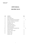
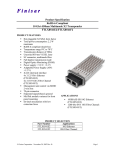
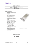
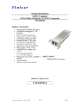
Technical
Information
Manual
Revision n. 0
21 April 1999
MOD. N 145
QUAD SCALER
AND
PRESET COUNTER/TIMER
C.A.E.N.
Document type:
User's Manual (MUT)
Title:
Mod. N145 Quad Scaler and Preset Counter/Timer Quad Scaler
and Preset Counter/Timer
Revision date:
20/04/1999
Revision:
0
TABLE OF CONTENTS
1.
MODEL OVERVIEW.......................................................................................................................... 4
2.
SPECIFICATIONS .............................................................................................................................. 6
3.
PERFORMANCE DATA..................................................................................................................... 7
3.1.
4.
5.
6.
POWER REQUIREMENTS .................................................................................................................... 7
PRINCIPLES OF OPERATION ......................................................................................................... 9
4.1.
SECTIONS 1 TO 4 .............................................................................................................................. 9
4.2.
SECTION 5 ....................................................................................................................................... 9
APPLICATION NOTES .................................................................................................................... 11
5.1.
GATED UP-COUNTING ..................................................................................................................... 11
5.2.
16- OR 24- DIGIT UP-COUNTING..................................................................................................... 11
5.3.
FREQUENCY MEASUREMENTS.......................................................................................................... 12
5.4.
DIVIDER ........................................................................................................................................ 12
5.5.
DELAY UNIT .................................................................................................................................. 12
5.6.
MEASUREMENT ACCURANCY .......................................................................................................... 13
TEST PROCEDURES........................................................................................................................ 14
6.1.
INTRODUCTION .............................................................................................................................. 14
6.2.
EQUIPMENT REQUIREMENTS ........................................................................................................... 14
6.3.
SEQUENCE OF OPERATIONS ............................................................................................................. 14
6.4.
TEST OF SECTION 5......................................................................................................................... 15
6.5.
TEST OF THE DISPLAYS (SECTION 1 TO 4) ......................................................................................... 16
6.6.
TEST OF THE COMPLETE MODULE .................................................................................................... 16
LIST OF FIGURES
FIG. 1.1 – MOD. N145 FRONT PANEL .............................................................................................................. 5
FIG. 3.1 – SECTION 5 - TIMING DIAGRAM ........................................................................................................ 8
Filename:
N145MAN
Number of pages:
16
Page:
3
C.A.E.N.
Document type:
User's Manual (MUT)
Title:
Mod. N145 Quad Scaler and Preset Counter/Timer
Revision date:
20/04/1999
Revision:
0
1. Model overview
C.A.E.N. Mod. N145 is a double unit NIM module that includes four independent 8-digit
up-counters, plus a fifth 7-digit down-counter that can be used either as a preset counter
or as timer.
The counters can have different operating modes and can be variously interconnected,
thereby making the module a flexible and powerful tool for several applications involving
time, frequency and ratio measurements.
All counters can accept either TTL or NIM inputs. All control and output signals are
standard NIM. The maximum input frequency is 80 MHz(∗ ) and the minimum pulse width
is 8 ns(∗ )for the up-counters, and respectively 30 MHz and 15 ns for the down-counter.
All input and output connectors as well as all the control switches are located on the front
panel. All input and output connectors are LEMO 00 type.
(∗ ) Minimum guaranteed performance data
(∗ ) Minimum guaranteed performance data
Filename:
N145MAN
Number of pages:
16
Page:
4
C.A.E.N.
Title:
Mod. N145 Quad Scaler and Preset Counter/Timer
Revision date:
20/04/1999
Revision:
0
NIM
IN
GATE
TTL
CH1
NIM
IN
GATE
TTL
CH1
NIM
IN
GATE
TTL
CH1
NIM
IN
GATE
TTL
CH1
NIM
IN
TTL
CH5
CH1
CH2
CH3
CH4
COMM
RESET
Document type:
User's Manual (MUT)
NORMAL
GATE
GT+ CLR
Fig. 1.1 – Mod. N145 Front Panel
Filename:
N145MAN
Number of pages:
16
Page:
5
C.A.E.N.
Document type:
User's Manual (MUT)
Title:
Mod. N145 Quad Scaler and Preset Counter/Timer
Revision date:
20/04/1999
Revision:
0
2. Specifications
SECTIONS 1 AND 3
INPUTS
2, one NIM and one TTL, 50 Ω impedance.
GATE
2, NIM bridged input ports, high impedance, internally
connected. Free port must be terminated on 50 Ω
SECTIONS 2 AND 4
INPUTS
2, one NIM and one TTL, 50 Ω impedance.
GATE
one NIM input, 50 Ω impedance.
CARRY
one NIM output. Generates apulse when counter has
fully cycled (transition 99,999,999 to 0).
RESET
one NIM input, clears sections 1 to 4. Same effect is
obtained, for each section, with the individual RESET
pushbuttons.
SECTION 5
INPUTS
2, one NIM and one TTL, 50 Ω impedance.
LOAD
one NIM input. Loads counter with value preset on the
thumb wheel switch display (same effect with LOAD
pushbutton).
OUT
2, NIM outputs, these are true(∗ )as long as counter
contents are different from zero.
END MARKER
one NIM output, a pulse generated when the counter
contents become zero. Pulse width is adjusted with
trimmer between 50 ns and 1 µs.
(∗ ) NIM level 1=-800 mV=TRUE
Filename:
N145MAN
Number of pages:
16
Page:
6
C.A.E.N.
Document type:
User's Manual (MUT)
Title:
Mod. N145 Quad Scaler and Preset Counter/Timer
Revision date:
20/04/1999
Revision:
0
3. Performance data
3.1.
INPUT
MAX. FREQUENCY
MIN. PULSE WIDTH
sections 1 to 4
80 MHz
8 ns
section 5
30 MHz
15 ns
load
10 ns
reset
10 ns
Power requirements
+6 V
2.5 A
−6 V
150 mA
All connectors are LEMO 00 type.
Filename:
N145MAN
Number of pages:
16
Page:
7
C.A.E.N.
Document type:
User's Manual (MUT)
Title:
Mod. N145 Quad Scaler and Preset Counter/Timer
Revision date:
20/04/1999
Revision:
0
NIM INPUT
LOAD
40 ns
min
10 ns
min
DISPLAY
DATA
0
3
2
1
0
120 ns dead time
OUT
≈ 35 ns
≈ 35 ns
END MARKER
Trimmer adjustable
Fig. 3.1 – Section 5 - Timing Diagram
Filename:
N145MAN
Number of pages:
16
Page:
8
C.A.E.N.
Document type:
User's Manual (MUT)
Title:
Mod. N145 Quad Scaler and Preset Counter/Timer
Revision date:
20/04/1999
Revision:
0
4. Principles of operation
4.1.
Sections 1 to 4
The counters can operate in three distinct modes, which are:
NORMAL
Free running. The counter is incremented by the input pulses.
GATE
The counter is incremented by input pulses only if the GATE
input is true.
GATE + CLEAR
Same as GATE mode, however the leading edge of the GATE
input clears the counter.
The modes are manually selectable, for each section, by the switches on the bottom row
of the front panel. The up-counters are reset to zero, either manually (individually for
each section) by acting on the RESET pushbuttons, or electrically (common to all
sections) by means of a NIM pulse on the COMM RESET input.
Sections 1 and 3 have two NIM high impedance GATE bridged inputs which are
internally connected; a NIM input must be terminated with a 50 Ω impedance at the
other port.
Sections 2 and 4 have one 50 Ω NIM GATE input and one CARRY output. The CARRY
output generates a NIM pulse when the counter has fully cycled (transition from max
counter value to zero). This can be used to extend the counters' range by cascading
sections, as shown later.
4.2.
Section 5
The fifth counter is a 7-digit counter that can operate as a PRESETTABLE DOWNCOUNTER or as a TIMER. Either mode is selected by the manual SOURCE SELECT
switch (labelled COUNTER/TIMER).
In COUNTER mode
the counter is decremented by the external (NIM or TTL) input
pulses.
In TIMER mode
the counter is decremented by an internal precise quartz clock,
independently of input pulses. The frequency is selectable by
acting on the TIMER switch and can be set to 1 KHz (1 ms) or
to 1 MHz (1 µs).
In either mode, the counter must be initally preset to the desired value by acting on the
Thumb wheel switches and then by loading the datum either manually with the LOAD
pushbutton or electrically with a NIM pulse. At the leading edge of the first input pulse
Filename:
N145MAN
Number of pages:
16
Page:
9
C.A.E.N.
Document type:
User's Manual (MUT)
Title:
Mod. N145 Quad Scaler and Preset Counter/Timer
Revision date:
20/04/1999
Revision:
0
the OUT ports become true. The counter is then decremented by the input pulses unntil
zero is reached. At the trailing edge of the last input pulse:
the OUT outputs are reset to FALSE (0 V)
the END MARKER output generates a NIM pulse the length of which can be adjusted
between 50 ns and 1 µs by acting on the trimmer next to the END MARKER connector.
This arrangement allows direct use of the OUT ports as GATE inputs to the counters of
section 1 to 4.
CYCLING of Section 5 is controlled by the SINGLE/REPEAT switch, which is labelled
SGL/RPT.
In SINGLE mode
the selected function (PRESET COUNTER or TIMER) is
performed only once, until zero is reached for the first time.
The counter must then be restarted by a new load operation.
In REPEAT mode
a few seconds after zero is reached the counter re-triggers
itself automatically, by performing an automatic LOAD, and a
new cycle is restarted. This procedure is repeated indefinitely.
Note that by connecting the END MARKER output to the LOAD input the counter is
cycled without the time delay of the REPEAT mode.
Filename:
N145MAN
Number of pages:
16
Page:
10
C.A.E.N.
Document type:
User's Manual (MUT)
Title:
Mod. N145 Quad Scaler and Preset Counter/Timer
Revision date:
20/04/1999
Revision:
0
5. Application notes
5.1.
Gated up-counting
When in NORMAL MODE, the counters (sections 1 to 4) do not require a GATE input.
However, when in GATE (of GATE+CLEAR) mode, a NIM signal must be supplied at the
GATE input of each counter used. NOTE: this signal must be terminated with a 50 Ω
impedance at the other GATE bridged input, on sections 1 or 3.
A single GATE signal can be fed in parallel, to more than one channel by using jumper
cables between sections 1 and 3, and sections 2 and 4; if the last section is either 2 or 4
then this also provides the correct 50 Ω cable termination. For example,
sections 1 and 2 can share a GATE by feeding the external GATE signal to the GATE
input of section 1 and then connecting a jumper between the other GATE output of
section 1 to the GATE input of section 2, which has a 50 Ω impedance. Similarly, it is
possible to connect up to three sections (for instance #1 with #3, and then #3 with #2 or
#4) with a single external GATE input cable and two jumpers.
The OUT signal of section 5 can be used as the GATE input to the counters. The double
OUT connector permits parallel GATE feeding of all four sections, as described above.
Using a common GATE to more sections allows direct ratio measurements among the
inputs to the various channels.
5.2.
16- or 24- Digit Up-Counting
It is possible to increase the up-counting range to 16 or 24 digits by using the CARRY
outputs of sections 2 and 4.
For instance, 16-digit up-counting is obtained by connecting the CARRY output of
section 2 to the NIM input of section 1. When the counter of section 2 has fully cycled
(transition 99,999,999 to zero) the CARRY output supplies a NIM input pulse to
section 1, and so on. Thus section 1 will show the most significant digits, and section 2
the least significant digits of the counting operation.
Similarly, for 24-digit up-counting, the CARRY output of, say, section 2 may be
connected to the NIM input of section 4; the CARRY output of section 4 may then be fed
to the NIM input of section 1 or 3.
Filename:
N145MAN
Number of pages:
16
Page:
11
C.A.E.N.
Document type:
User's Manual (MUT)
5.3.
Title:
Mod. N145 Quad Scaler and Preset Counter/Timer
Revision date:
20/04/1999
Revision:
0
Frequency measurements
This is a way of making relative frequency measurements.
By using section 5 in TIMER MODE, it is possible to make an absolute frequency
measurement, with a variable integration time. For that purpose:
•
select the clock rate:
with the TIMER switch:
•
ƒ=1/τ
(τ=1 µs or 1 ms)
select a value N (for instance a power of 10) with the thuimb wheel switches. The
integration time is then:
Ti=Nτ
• use the OUT signal as the GATE input to the selected section 1 to 4 Counter(s),
operating in GATE+CLEAR mode.
The external input frequency is then given by:
where
5.4.
ƒi=(Mc)/(Nτ)
is the number of pulses received by the Counter while GATE is active.
Divider
Section 5 can also be used as a divider of an external input sequence. For that purpose:
5.5.
•
connect the END MARKER output to the LOAD input.
•
Select the input / output ratio R by setting the thumb wheel switches.
•
Connect the external input at the section's input port and take the (decimated) NIM
output at the OUT ports. That is, a pulse is generated at the OUT port every R
pulses at the input.
Delay unit
Section 5 can also be used to generate a delayed pulse (at the END MARKER output) or
transition (at the OUT ports).
An absolute delay can be otained with section 5 in TIMER Mode. The duration of the
delay is Td=N.τ where N is the preset value on the Thumb wheel switch display, and τ is
the internal clock period. The time delay is the elapsed time between the time of the
leading edge at the LOAD input and leading edge either at the END MARKER output or
at the OUT connectors. See the next section for accuracy. With the counter in
COUNTER Mode, a relative delay (in terms of number of pulses) can be obtained
between the NIM or TTL input and the END MARKER or OUT connectors, after the
preset number of input pulses have been counted.
Filename:
N145MAN
Number of pages:
16
Page:
12
C.A.E.N.
Document type:
User's Manual (MUT)
5.6.
Title:
Mod. N145 Quad Scaler and Preset Counter/Timer
Revision date:
20/04/1999
Revision:
0
Measurement accurancy
For the previous applications, it is important to remember that with any measurement
made with a counter on a periodic waveform there is always an intrinsic uncertainty of
one pulse. This is due to the fact that, depending on the position of the start of the
measurement window with respect to the period of the waveform, one pulse may or may
not be totally included, and thus counted for. This also applies to the uncertainty of the
selection of the reference time window.
The uncertainty of the measurement of an absolute time delay is therefore equal to , the
clock period.
For frequency measurements it is:
∆ƒi=ƒmax−ƒmin=(Mc)/(Nτ)−(Mc-1)/(Nτ)=1/(Nτ)
where ∆ƒi is the absolute frequency uncertainty. The relative frequency uncertainty is
then:
∆ƒi=1−(Mc)
and since for a given (constant) frequency Mc(=Nƒτ) is proportional to N, the percent
accuracy is increased by increasing N.
Filename:
N145MAN
Number of pages:
16
Page:
13
C.A.E.N.
Document type:
User's Manual (MUT)
Title:
Mod. N145 Quad Scaler and Preset Counter/Timer
Revision date:
20/04/1999
Revision:
0
6. Test procedures
6.1.
Introduction
Mod. N145, as all other CAEN products, was designed by out engineers with particular
attention to reliability. It was built with the utmost care and thoroughly tested to meet and
exceed the reliability standards for this class of equipment. Proper handling of the unit
should result in long-lasting trouble-free operations.
The following test procedures are given here essentially for initial equipment check-out
or simple troubleshooting should a malfunction be suspected. They provide the rational
for simple yet consequential tests to single out the possible causes of problems. If these
tests do not help you out, or if a major malfunction is detected, please refer to C.A.E.N.
Technical Service.
The tests can be made with general-purpose equipment as indicated below; however
they can also be conveniently performed using CAEN modules. In the following, italic
text is used to describe equipment and procedures specifically applicable with CAEN
products.
6.2.
6.3.
Equipment requirements
•
One Dual Trace Oscilloscope,
•
one Fan-out of four device (4-way discriminator, Mod. N84),
•
one Waveform Generator (up to 100 MHz),
•
two delayed Pulse Generators, (or three Dual Timers, Mod. N93B)
Sequence of operations
An overall testing of the module involves three steps.
1. Test of section 5,
2. Test of the Displays,
3. Test of Complete Module.
Filename:
N145MAN
Number of pages:
16
Page:
14
C.A.E.N.
Document type:
User's Manual (MUT)
6.4.
Title:
Mod. N145 Quad Scaler and Preset Counter/Timer
Revision date:
20/04/1999
Revision:
0
Test of section 5
Test N°1 (No External Connections)
For each digit, preset all values (0-9) and, by pressing LOAD, check that the value is
correctly loaded into the LED display.
Test N°2 (TIMER mode - Cycle Switch on SINGLE)
This test is meant to check in a compact way the proper operation of several functions.
These are the operations of the internal quartz, the LOAD, the OUT and the END
MARKER functions.
To perform the test, generate with the Delayed Pulse Generator a NIM pulse triggered
by, but not to be overlapped to, the END MARKER pulse, with a variable delay from the
leading edge of the END MARKER and a minimum pulse width of 10 ns. This pulse is
used to drive the LOAD input. To generate this pulse with CAEN hardware connect the
END MARKER output to the input of one section of a Dual Timer, which acts as a
variable delay; the end marker of this section is connected to the input of the other
section. Use the end marker of this last section as the LOAD input of module N145. The
delay must be such that the LOAD pulse must take place when the END MARKER pulse
is finished.
Now preset the value of 1 µs and press LOAD. Model N145 must cycle; the LED displays
must go to zero and the OUT signal, checked with a scope, must be equal to 1 µs + the
transit time of the counter's chain (about 80 to 100 ns).
Check also that the END MARKER output can be made to vary between 50 ns and 1 µs.
Preset any time value, both in µs and in ms, and check with the scope that the Out
signal has the preset length. Perform this test with the cycle switch also in REPEAT
mode; the correct value should appear about every two seconds.
Test N°3 (COUNTER Mode - Cycle switch on SINGLE)
This test is similar to the previous one, the only difference being that the source of the
test clock is this time external. This is to test that the COUNTER mode operates
properly.
Drive the counter at its NIM input with an oscillator with a variable frequency up to
30 MHz. The set-up is just as described for Test N°2. Preset on the thumb wheel switch
a value N. Check on the scope that the OUT signal has a time length of where is the
external clock period.
Check also the TTL input in the same manner.
Filename:
N145MAN
Number of pages:
16
Page:
15
C.A.E.N.
Document type:
User's Manual (MUT)
6.5.
Title:
Mod. N145 Quad Scaler and Preset Counter/Timer
Revision date:
20/04/1999
Revision:
0
Test of the displays (section 1 to 4)
Test N° 4
With an oscillator, send pulses, at a variable clock rate, at the NIM input of each section
and check that the LED displays are correctly showing all digits and that the CARRY be
generated at the 9-0 transition.
Test N°5
Purpose of this test is to check that the counter does not accept an input pulse before
the leading edge of the GATE signal (within 2 ns).
For that, use two Delayed Pulse Generators to obtain two pulses with variable mutual
delay. With CAEN hardware, use a Dual Timer configured as oscillator and take two
outputs and send them to two different delay chains; then drive the two sections of a
second Dual Timer.
Preset the widths of the output pulses to 100 ns and 40 ns respectively. Send the 100 ns
signal to the GATE input and the 40 ns signal to the NIM input of the N145. (Provide
matching 50 Ω impedance if required). Select GATE+ CLEAR mode and, acting on the
delay chains, verify that the display counts one pulse until the leading edge of the input
is within 2 ns or less from the leading edge of the GATE.
6.6.
Test of the complete module
These tests are performance checks on the operation of the counters.
Test N°6
With an oscillator and a fan-out of 4 make four 8 ns pulses. (Use cables of equal length).
Drive the four NIM inputs of sections 1 to 4. Set GATE+CLEAR mode and use section 5
(set to TIMER mode and REPEAT mode) to generate the GATE signal. At every cycle
the counters must show the same value. Repeat the test using the TTL inputs.
Test N°7 (check of CARRY)
Manually RESET section 1 to 4 and set NORMAL mode. Use as input to section 2 and 4
the same as described at point 1. For sections 1 and 3 use the CARRY output of
sections 2 and 4. Start the clock and after some time stop it. The values of
sections 1 and 3 must be identical, so as the values of sections 2 and 4. Repeat this
operation several times.
Test N°8 (check of RESET)
Let section 1 to 4 count for some time, then send a 10 ns pulse at the COMM RESET.
The sections must reset to zero. Repeat this operation several times.
Test N°19
Set GATE mode and use a 5 MHz Oscillator. With section 5 (set to TIMER mode with
1 MHz clock, and in repeat mode) generate the GATE signal. Preset the value 1000 with
Filename:
N145MAN
Number of pages:
16
Page:
16
C.A.E.N.
Document type:
User's Manual (MUT)
Title:
Mod. N145 Quad Scaler and Preset Counter/Timer
Revision date:
20/04/1999
Revision:
0
the thumb wheel switches. The display of the tested section must increment by 5000
every cycle. Repeat this operation several times.
Filename:
N145MAN
Number of pages:
16
Page:
17