1
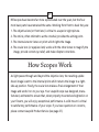
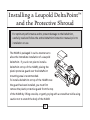
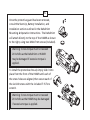
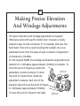
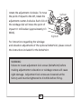
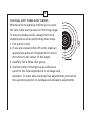
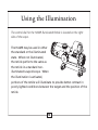
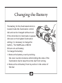
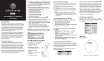
HAMRTM
(High Accuracy Multi-Range)
4x24mm Riflescope
User's Manual
www.leupold.com
Part# 113492
Artwork# 113491
Table of Contents
Know Your Scope . . . . . . . . . . . . . . . . . . . . . . . . . . . . . . . . . . . . . . . . . . . . . . Page 2
Installing a DeltaPointTM and Protective Shroud . . . . . . . . . . . . . . . . . . . . . Page 4
Mounting the Scope . . . . . . . . . . . . . . . . . . . . . . . . . . . . . . . . . . . . . . . . . . . . Page 6
Making Precise Elevation and Windage Adjustments . . . . . . . . . . . . . . . Page 11
How to Sight-In . . . . . . . . . . . . . . . . . . . . . . . . . . . . . . . . . . . . . . . . . . . . . . . Page 14
Using the Illumination . . . . . . . . . . . . . . . . . . . . . . . . . . . . . . . . . . . . . . . . . Page 18
Changing the Battery . . . . . . . . . . . . . . . . . . . . . . . . . . . . . . . . . . . . . . . . . . Page 20
Leupold Means Minimal Maintenance . . . . . . . . . . . . . . . . . . . . . . . . . . . . Page 23
Leupold Product Service . . . . . . . . . . . . . . . . . . . . . . . . . . . . . . . . . . . . . . . . Page 27
Know Your Scope
9
7
8
4
3
2
1
5
1.
2.
3.
4.
5.
6.
Ocular Lens
Diopter Adjustment Ring
Diopter Lock Ring
Elevation Adjustment Screw
Windage Adjustment Screw
Illumination Control Dial
(Right Side of Scope)
7.
8.
9.
DeltaPoint Sight
Objective Lens
DeltaPoint Protective Shroud
6
2
3
Riflescopes have become far more sophisticated over the years, but the four
most basic parts have remained the same. Working from front to back they are:
1. The objective lens (or front lens) is critical to a superior sight picture.
2. The reticle, often referred to as the crosshair, provides the aiming point.
3. The internal erector lenses or prism which rights the image.
4. The ocular lens (or eyepiece lens) works with the other lenses to magnify the
image, provide correct eye relief, and make diopter corrections.
How Scopes Work
As light passes through and beyond the objective lens, the resulting upside
down image is sent to the internal prism which returns the image to a rightside-up position. Finally, the ocular lens makes a final enlargement of that
image and sends it on to your eye. Your Leupold scope was designed, manufactured, and tested to ensure that, when properly mounted and sighted-in on
your firearm, you will enjoy exceptional performance. A solid mount is critical
to satisfactory performance of your scope. If you have questions or concerns,
please contact Leupold Product Service (see page 27).
Installing a Leupold DeltaPoint™
and the Protective Shroud
For optimum performance and to prevent damage to the DeltaPoint,
carefully read and follow the entire DeltaPoint instruction manual prior to
installation or use.
The HAMR is packaged in such a manner as to
allow the immediate installation of a Leupold
DeltaPoint. If you do not plan to install a
DeltaPoint on top of the HAMR, placing the
plastic protecive guard over the DeltaPoint
mounting area is recommended.
To install a DeltaPoint on top of the HAMR once
the guard has been installed, you must first
remove the plastic protective guard from the top
of the HAMR by lifting one side, or gently prying with a screwdriver while using
caution not to scratch the body of the HAMR.
4
5
Once the protective guard has been removed,
consult the Start-Up, Battery Installation, and
Installation sections outlined in the DeltaPoint
Mounting & Operation Instructions. The DeltaPoint
will attach directly to the top of the HAMR as shown
to the right, using two M4x0.7mm screws (included).
Warning: Screw torque must not exceed
20 inch/lbs as the DeltaPoint or HAMR
may be damaged if excessive torque is
applied.
To install the protective shroud, simply slide it into
place from the front of the HAMR until each of
the screw holes are aligned, then secure each of
the six 8-40 screws with the included T-15 Torx
wrench.
Warning: Screw torque must not exceed
20 inch/lbs as the HAMR may be damaged
if excessive torque is applied.
Mounting the Scope
FLAT-TOP MOUNTING PROCEDURE
Preparing the Leupold HAMR 4x24mm scope for flat-top
(MIL-STD-1913) mounting:
1. Loosen the 1/2-inch hex nuts of the Mark 4 Base until they are near the end of
its cross bolts.
2. Using the two 1/4-32 hex-head screws, attach HAMR to the Mark 4 Base
using any of the four tapped holes in the bottom of the scope; secure using
a torque value of 50 inch/lbs. Note: The Mark 4 Base is typically attached so
the hex nuts are on the same side of the scope as the illumination control dial.
The base can be attached with the hex nuts on the opposite side but the suggested configuration avoids snagging of clothing for right-handed shooters.
Mounting the Leupold HAMR 4x24mm scope on a flat-top
(MIL-STD-1913) mounting rail:
1. Place the Leupold HAMR 4x24mm scope atop the MIL-STD-1913 mounting rail
so that the recoil lugs of the Mark 4 Base engage the cross slots of the rail.
6
7
2. Holding the scope in place, check the eye relief of the scope; adjust the
position of the scope as necessary until the recoil lugs engage the rail’s
cross slots in a position that allows for a full sight picture when the firearm
is shouldered. Note: Additional adjustment can be obtained by using
alternate mounting holes in the bottom of the HAMR when attaching the
Mark 4 Base to the scope.
3. Make certain that both recoil lugs engage the MIL-STD-1913 mounting rail
cross slots and that the Mark 4 Base rails hook over each side of the MILSTD-1913 mounting rail.
4. With one hand atop the scope pressing down and forward to ensure a
solid mount engagement, finger tighten the hex nuts of the base until the
assembly is snug.
5. Using a 1/2-inch hex wrench or socket, alternately tighten each nut until
the mounting bracket is secure.
6. Complete the installation by using a torque wrench and 1/2-inch socket to
apply 65 inch/lbs of torque to each hex nut. (The use of the Mark 4 Torque
Wrench is recommended for this procedure.)
NOTE: The windage and elevation adjustments on new Leupold scopes are centered
as part of the assembly process. If you are mounting a scope that was previously
mounted on another rifle, you should center the adjustments (please see CENTERING
WINDAGE AND ELEVATION ADJUSTMENTS TO ACHIEVE OPTIMUM ADJUSTMENT
TRAVEL ON PAGE 13).
ESTABLISHING EYE RELIEF
Because of the safety considerations associated with proper eye relief, Leupold
strongly recommends that you mount your scope as far forward as possible.
Beyond that, follow these steps:
1. With the scope as far forward on the rail as possible, hold the rifle in
your normal shooting position.
2. Slowly move the scope to the rear just until you can see a full sight picture.
3. Position your scope here for maximum eye relief.
NOTE: To confirm that your scope is mounted in the best possible position, try assuming various positions: kneeling, seated, prone, and aiming both uphill and downhill.
Remember that aiming uphill typically reduces eye relief. Wearing hunting/shooting
specific clothing is recommended as this may alter eye relief considerations slightly.
8
9
WARNING
If a scope is mounted too far to the rear, the eyepiece can injure the shooter’s brow. Shooting at an uphill angle also increases this hazard because
it shortens the distance between the brow and the rear of the scope. For
this reason, Leupold scopes are engineered to provide generous eye relief.
Therefore, when mounting your scope, we recommend positioning it as far
forward in the mounts as possible to take full advantage of this generous
eye relief.
FOCUSING THE RETICLE
Secure the scope and firearm in a firm rest. Safely point the scope at a light
colored background object. With the scope approximately three inches from
your eye the reticle should appear sharp and crisp; if it does not, it is necessary
to adjust the focus by means of the eyepiece.
1. Grasp the thin knurled lock ring near the rear of the eyepiece and back it
away from the eyepiece, toward the rear of the scope.
2. If you tend to hold things away from yourself to see them clearly (you are
farsighted) turn the rear-most portion of the eyepiece counter-clockwise
a couple of turns. If you hold things close to yourself to see them clearly
(you are nearsighted) turn the rear-most portion of the eyepiece clockwise
a couple of turns.
3. Looking through the scope when pointed at the light colored background
object, take a few quick glances at the reticle. The focus of the reticle
should be noticeably different than when you started. Continue this process until the reticle appears clear and sharp.
4. When you are satisfied with the image of the reticle, turn the lock ring
clockwise so that it rests firmly against the eyepiece.
10
11
Making Precise Elevation
And Windage Adjustments
The style of elevation and windage adjustments on Leupold
riflescopes varies with specific models. Each, however, is clearly
marked in easy to read increments. If, for example, there are four
hash marks from zero to (and including) the number one on an
adjustment knob, then the value of each increment of adjustment
on that knob is 1/4-MOA.
For the Leupold HAMR, the windage and elevation adjustments are
marked in 0.1 milliradian (approximately 1/3 MOA) increments. To
move the point of impact up, rotate the
Up/Down
adjustment counter-clockwise. To move
the point of impact down, rotate the
adjustment clockwise. Each click of the
elevation dial will move the point of impact
0.1 milliradian (approximately 1/3 MOA).
To move the point of impact to the right,
Right/Left
rotate the adjustment clockwise. To move
the point of impact to the left, rotate the
adjustment counter-clockwise. Each click of
the windage dial will move the point of
impact 0.1 milliradian (approximately 1/3
MOA).
Up/Down
Right/Left
For instructions regarding the windage
and elevation adjustments of the optional DeltaPoint, please consult
the instructions included for the DeltaPoint.
WARNING:
Failure to loosen adjustment lock screws (DeltaPoint) before
making adjustments to elevation or windage screws will cause
sight damage. Adjustment lock screws are loosened at the
factory and must be tightened to 4 inch/lbs before firing.
12
13
CENTERING WINDAGE AND ELEVATION ADJUSTMENTS TO
ACHIEVE OPTIMUM ADJUSTMENT TRAVEL
Making windage and elevation adjustments moves an internal
mechanism horizontally and vertically inside the scope. If this
mechanism is off to one side, the adjustments won’t provide equal
travel in all directions. To regain full balanced travel, you must
recenter the adjustments as follows:
1. Turn the windage adjustment to the point that it stops moving.
2. Counting the clicks or hash marks, turn it all the way in the other
direction.
3. Turn the dial back half the amount of clicks or hash marks
counted.
4. Repeat this process for the elevation adjustment.
How to Sight-In
USING A BORE-SIGHTING COLLIMATOR
To save time and ammunition, start out in your shop or gun room
with a bore-sighting collimator. Follow the directions included with
the collimator for specific instructions on its proper use.
NOTE: Bore-sighting alone is not sufficient to sight-in a scope. You must make final
adjustments by shooting the firearm using the same ammunition you use in the field.
USING THE LEUPOLD ZERO POINT® ILLUMINATED MAGNETIC BORESIGHTER
This tool fits any rifle, shotgun, or pistol, and helps you get “on the
paper” fast, without barrel spuds. It works with any optical sight,
and can even be used to recheck your zero, without firing a shot. See
your Leupold Golden Ring Dealer or visit www.leupold.com for more
information.
14
15
TRADITIONAL BORESIGHTING OF AR-15 AND M-16 FIREARMS USING
A TARGET
from 20 to 50 yards away:
1. Position the firearm on the bench, using sandbags to steady the firearm as
necessary.
2. Release the rear receiver pin of the firearm.
3. Separate the upper and lower receiver halves.
4. Remove the bolt.
5. Position the firearm with the muzzle facing the target.
6. Looking through the bore itself, move the firearm to center the bull’s-eye of
the target inside the barrel.
7. Hold the rifle steady. With the bull’s-eye centered when viewed through the
bore, make windage and elevation adjustments to the scope until the very
center of the reticle is aligned with the bull’s-eye of the target (see figures A
and B on the next page).
TRADITIONAL BORE-SIGHTING (BOLT ACTIONS)
Preliminary sighting-in can also be accomplished by bore-sighting at
the firing range using a target from 20 to 50 yards away.
1. Position the firearm on the bench, using sandbags to steady the
firearm.
2. Remove the bolt from the firearm.
3. Looking through the bore itself, move the firearm to center the
bull’s-eye of the target inside the barrel.
4. Hold the rifle steady. With the bull’s-eye centered when viewed
through the bore, make windage and elevation adjustments to
the scope until the very center of the reticle is aligned with the
bull’s-eye of the target.
Figure B
Figure A
Target as seen through the bore.
16
17
THE FINAL STEP: THREE-SHOT GROUPS
Whichever bore-sighting method you’ve used,
the next steps are the same on the firing range.
To ensure reliable results, always fire from a
rested position when performing these steps.
1. Fire a shot or two.
2. If you are several inches off center, make an
appropriate amount of adjustment to move
the reticle to the center of the target.
3. Carefully fire a three-shot group.
4. Use the center of that group as a reference
point for the final adjustments to windage and
elevation. To learn about making final adjustments, proceed to
the upcoming section on windage and elevation adjustments.
Using the Illumination
The control dial for the HAMR Illuminated Reticle is located on the right
side of the scope.
The HAMR may be used in either
the standard or the illuminated
state. When not illuminated,
the reticle performs the same as
the reticle in a standard nonilluminated Leupold scope. When
the illumination is activated,
portions of the reticle will illuminate to provide better contrast in
poorly lighted conditions between the target and the position of the
reticle.
18
19
To illuminate the reticle:
1. Grasp the illumination dial located on the right side of the
adjustment turret.
2. Turn the dial clockwise from the OFF position to the first number
indicated on the dial.
3. View the target through the scope to determine if the reticle is
bright enough to stand out clearly against the target.
4. If more illumination is required, continue turning the dial
clockwise until the reticle is clearly visible against the target. The
first 2 settings are night vision compatible, while settings 3-7 are
intended for use in brighter situations.
5. For convenience, there is an OFF position located between each
of the intensity settings, allowing you to preserve the battery
and quickly obtain your preferred illumination setting.
Changing the Battery
The battery for the illuminated reticle is
located inside the illumination control
dial and can be changed without tools.
If the reticle fails to illuminate or appears
dim even on the highest illumination
setting, it is necessary to change the
battery. The HAMR uses a CR2032
lithium coin-cell battery.
To change the battery:
1.Remove the battery cover by twisting
the cover counter-clockwise while holding the sides of the
illumination dial to keep the entire dial from turning.
2. Remove the old battery from its position in the center of
the dial.
20
21
This can be done in two ways:
(A) Grasp the edges of the battery between the thumb and
forefinger and lift it free of the dial.
OR
(B) Turn the scope so that the illumination dial faces downward
and gently tap the illumination control against the edge of your
palm.
3. Insert the new battery, positive (+) side up.
4. Replace the battery cover on the illumination dial and turn it
clockwise until it is secure, while holding the sides of
the illumination dial to keep the entire dial from turning.
Replacement 3-volt lithium batteries
CR2032 batteries are becoming as common and are as readily
available as typical battery sizes ( AAA, AA, C, and D). Replacement
CR2032 lithium coin batteries can be purchased at most stores
where batteries are sold. Use only high quality battery brands such
as Sony®, Energizer®, Panasonic®, or Duracell® for safe and efficient
battery performance.
INSTALLING A LENS ATTACHMENT
Many Leupold scopes offer threaded objective and eyepiece rings to
allow for the attachment of lens covers and a variety of Alumina®
accessories. These attachments thread directly into the objective or
eyepiece rings. Turn until finger tight – do not over tighten.
22
23
Leupold Means Minimal
Maintenance
LENSES
Leupold scope lenses are coated to reduce light reflections and light
scattering, thus increasing light transmission through the scope. They
should be cleaned as carefully as you would a camera lens. Begin by
using a lens brush to remove dust and then pure alcohol, high-grade
glass cleaner, or pure water on a cotton swab.
WINDAGE / ELEVATION ADJUSTMENTS
These adjustments are permanently lubricated. There is no need to
lubricate them.
EYEPIECE
The eyepiece is permanently lubricated. There is no need to lubricate it. The eyepiece can be rotated as far as it will go in either
direction, it will not detach from the scope as there is an internal
lock ring.
SEALS
Leupold scopes are sealed from within by several methods, including O-rings. All seals are permanent and require no maintenance.
SCOPE EXTERIOR
Leupold scopes are made of rugged 6061-T6 aircraft aluminum
alloy. No maintenance of any kind is required; simply wipe off any
dirt or fingerprints that accumulate with a clean, dry cloth.
24
25
TROUBLE SHOOTING TIPS
Before you ship a scope back to the factory for service or repair,
please check the following items:
1. Check the mount to make sure the scope is mounted securely
to the rifle. Try, with bare hands only, to gently twist the scope
or see if anything moves when you jiggle it. If there is
any movement, retighten the mounting system according to
mounting instructions.
2. Make sure the action of your rifle is properly bedded in the stock,
and that all receiver screws are tight and have been tightened in
the sequence recommended by the manufacturer. A loosely fitted
stock can cause changes to the point-of-impact.
3. When test firing a rifle to check the point-of-impact relative to
windage and elevation adjustments, be sure to fire from a solid
bench with sandbags supporting the forearm and buttstock.
4. Be sure to use factory-loaded ammunition of the same bullet type,
weight, and preferably, lot number. If one type of ammunition
does not shoot well, try another brand or bullet weight.
5. Be certain that both the barrel and chamber are clean. Heavy
factory grease or copper fouling can diminish the accuracy of the
firearm.
26
27
Leupold Product Service
If your Leupold scope fails to perform in any way, you may return it directly to
the factory for service. We recommend contacting Leupold Technical Service at
1-800-Leupold (538-7653), and following these shipping instructions:
1. Remove the base and any other accessories from the scope.
2. Record the serial number of the scope and keep it for
your records.
3. Include a note with your name, address, telephone number, E-mail, and a
description of the problem.
4. Pack the scope in its original box (if you have it), as this is the safest
shipping container. Wrap the package securely using filament strapping
tape on the outside.
5. Ship the scope by parcel or mail service (insured, if possible) to one of the
following addresses:
In the United States:
Parcel Service:
Leupold Product Service
14400 NW Greenbrier Parkway
Beaverton, OR 97006-5790
USA
By Mail:
Leupold Product Service
P.O. Box 688
Beaverton, OR 97075-0688
USA
Outside the United States:
Canada: Korth Group Ltd., 103 Stockton Point, Box 490 Okotoks, AB T1S 1A7,
Canada
Germany: Harold Ros, Coburger Strasse 71, 98673 Eisfeld, Germany
Sweden: HDF Gyttorp Jakt AB, Svarvaregatan 5, S-302 50 Halmstad, Sweden
Our Product Service telephone numbers are (503) 526-1400 or (800) LEUPOLD
(538-7653), fax is (503) 352-7621. They can also be contacted through our
Web site at www.leupold.com.
28
29
Leupold Tactical Products
Warranty
Warranties on Leupold Tactical optical products vary depending on use and
other factors. For more information regarding warranties on these products,
contact Leupold at (503) 526-1400 or 1-800-Leupold (538.7653).
LEUPOLD MAKES MORE THAN SCOPES
See our complete line of rangefinders, mounting systems, binoculars, spotting
scopes, flashlights, and accessories at your nearest Leupold dealer.
For a free Leupold catalog, write to:
Leupold & Stevens, Inc., P.O. Box 688, Beaverton, OR 97075,
call (503) 526-1400 or (800) LEUPOLD (538-7653),
or send us an E-mail through our Web site at www.leupold.com.
30
31
LEUPOLD, GOLDEN RING, MARK 4, the Golden Ring design, the circle-L reticle logo design, and various other marks are
registered trademarks of Leupold & Stevens, Inc. All marks, including corporate logos and emblems, are subject to Leupold’s
rights and may not be used in connection with any product or service that is not Leupold’s, or in any manner that disparages
or discredits Leupold, or in a manner likely to cause confusion.
Certain other trademarks used in connection with Leupold products and services are the property of their respective owners,
and are used with permission. BOONE AND CROCKETT CLUB and BOONE AND CROCKETT are registered trademarks of
the Boone and Crockett Club. NWTF is a registered trademark of the National Wild Turkey Federation. QDMA, and QUALITY
DEER MANAGEMENT are trademarks or registered trademarks of the Quality Deer Management Association. RMEF and
ROCKY MOUNTAIN ELK FOUNDATION are registered trademarks of the Rocky Mountain Elk Foundation. ADVANTAGE
TIMBER and ADVANTAGE TIMBER HD are trademarks or registered trademarks of Jordan Outdoor Enterprises Ltd. MOSSY
OAK BREAK-UP, MOSSY OAK BRUSH, MOSSY OAK OBSESSION, and MOSSY OAK TREESTAND are trademarks or registered
trademarks of HAAS Outdoors, Inc. A.R.M.S. is a registered trademark of Atlantic Research Marketing Systems, Inc. The ARD
(anti-reflection device) is manufactured by Tenebraex Corp. under the name KillFlash, which is a trademark of Tenebraex
Corp.
We reserve the right to make design and/or material modifications without prior notice.
Copyright © 2010 Leupold & Stevens, Inc. All rights reserved.
Notes
32
33
Notes
Notes
34