1
2 Working principles
TDR-410 measures the time course of the signal (the probe pulse) in a pair from connecting the cable
to the cable end or the nearest damage and back.
Probe pulses in the cable run at a speed Vp (the speed of propagation), which depends on the electrical parameters of the cable, in particular the material from which the insulation is made.
A reflectometer calculates the distance to the disturbance of wave impedance path and displays the
cable's diagram showing any impedance discontinuity in the studied area based on Vp values selected by a user and and measured the course time of the pulse.
Output via2x4mm
safety sockets
LCD display
Cursor left key / decrease
selected value
Cursor right key / increase
selected value
START fault location
/ scan hold (for MFL)
Navigation button
Back light on/off
Escape / Return
Power on / off
3 Preparing the TDR-410 for use
Press button
1.
2.
3.
to power the tester, the following screen will be displayed:
Model.
Software version programmed into tester.
Battery condition indicator (all black battery, fully charged, as charge decreases symbol changes
to white). Battery condition indicator is permanently displayed.
To select a menu display, press the left button
6
as indicated on the TDR-410 front panel:
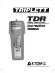
TDR-410 OPERATING MANUAL
version 1.01