1
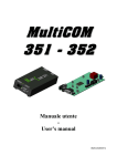
M ulti I /O O - User’s manual - IIN N ON TIIO CT UC DU OD RO TR NT Thank you for choosing a product from our Multi I/O range. The accessorys described in this manual are high quality products that have been carefully designed and manufactured to ensure the highest performance. This manual provided detailed instructions on how to use and install the accessory. Please READ THE MANUAL CAREFULLY BEFORE YOU USE THE MULTI I/O and keep it handy near the device for consultation on how to take full advantage of the features of your new purchase. © No part of this publication may be reproduced without the prior written permission of the manufacturer. The manufacturer reserves the right to make improvements to the equipment described in this manual at any time and without prior notice. - ENGLISH - 25 S SA AF FE ET TY Y This part of the manual contains SAFETY instructions that should be followed scrupulously. ¾ The equipment must not be used without a ground connection if it is powered at high voltage. ¾ Ensure that the connectors subjected to high voltages are correctly isolated. ¾ All the models in this range have been built for professional purposes and are therefore not suitable for use in a domestic environment. ¾ The equipment has been designed for use in closed environments. It should not be installed near inflammable liquids, gas or any other toxic substances. ¾ Ensure that water or any other liquid and/or objects do not fall into the equipment. ¾ Do not attempt to repair any failures and/or abnormal operation, but contact the nearest technical support centre. ¾ The equipment must be used only for the purpose for which it was designed. Any other use is considered improper and therefore dangerous. The manufacturer is not liable for any damage caused by improper, incorrect or unreasonable usage of the equipment. 26 - ENGLISH - O W EW VIIE RV ER OV VE DESCRIPTION 28 PRESENTATION 28 SERIAL 1 / SERIAL 3 COMMUNICATION PORT 29 SERIAL 2 COMMUNICATION PORT 29 INPUTS 30 OUTPUTS 31 FIRMWARE UPGRADE 32 INSTALLATION 33 OPENING THE PACKAGING AND CHECKING ITS CONTENTS 33 SOFTWARE CONFIGURATIONS 34 JUMPER CONFIGURATION 34 ADDRESS CONFIGURATION 36 TERMINATION RESISTANCE OF THE RS-485 BUS 36 CONNECTORS 37 TECHNICAL SPECIFICATIONS SERIAL CABLE SPECIFICATIONS MODBUS/JBUS PROTOCOL 40 40 41 SUPPORTED FUNCTION 41 TABLES OF STATES, MEASUREMENTS, NOMINAL DATA AND COMMANDS 41 COMMANDS CODES 44 - ENGLISH - 27 D N ON TIIO PT RIIP CR DEESSC PRESENTATION Multi I/O has been designed to integrate the UPS monitoring with configurable input and output management. The accessory, which must be connected to the UPS through a serial interface, manages 8 inputs (configurable as digit input, analog input or temperature sensor) and 8 clean contact relay outputs (configurable in accordance with the inputs and the UPS operating mode). The UPS status and that of the device can be monitored from the three separate serial lines (SERIAL 1, SERIAL 2 and SERIAL 3). The accessory is compatible with all UPS models that use GPSER and SENTR communication protocols (PRTK: GPSER1…, SENTR1...). The device can be powered either at 230 VAC or 9 VDC. There are two versions of Multi I/O available - a “BOX” version and the “O.F.” (Open Frame) version. Both versions have the same features and the contents of this manual apply to both products (unless otherwise specified). “BOX” version 28 “O.F.” version - ENGLISH - D N ON TIIO PT RIIP CR DEESSC SERIAL 1 / SERIAL 3 COMMUNICATION PORT The SERIAL 1 / SERIAL 3 communication port offers two RS-232 serial lines that can be used to monitor the UPS with the following protocol: Protocol Baud Rate [bps] Parity Stop bit GPSER 1200 None 1 To use the SERIAL 1 and SERIAL 3 lines, connect the supplied serial cable as indicated in the figure below. SERIAL 1 SERIAL 3 SERIAL 2 COMMUNICATION PORT The SERIAL 2 port has one Half-Duplex RS-485 serial line or an RS-232 serial line that can be used to monitor the UPS with the following protocols: Protocol GPSER MODBUS / JBUS RTU Baud Rate [bps] 1200 2400 4800 9600 19200 Parity None Stop bit 1 Equal Odd 2 N.B. The values shown in bold are the default configuration values. When the GPSER protocol is used on the SERIAL 2 port: ¾with RS-232 line, the device address must be set to zero ¾with RS-485 line, the device address must not be set to zero N.B. see the paragraph on “Address configuration”. - ENGLISH - 29 D N ON TIIO PT RIIP CR DEESSC INPUTS The eight inputs can be configured separately one from the other as: x Digital input x Analog input with 0V - 5V range x Temperature sensor with –20°C - 120°C range (supplied with the accessory). A pull-up or pull-down resistance can be selected for each input. If an input is configured as an analog input or as a temperature sensor, a greater and/or lower threshold value can be associated with it. It is also possible to define the delay between one signal detected on the input and the next. The delay value must be in the range 10 – 2,500 ms. If the input is configured as an analog input or temperature sensor, the predetermined delay coincides with the time interval during which n signal samples are recorded with a sampling frequency of 10 ms (n = delay[ms] / 10). An average is then taken on the n samples. If the input is configured as a digital, it is still sampled every 10 ms. If the sampled value is greater than 2.5V, a counter is incremented, or if the value is lower than 2.5V, a counter is decremented. When the counter reaches value n = delay[ms] / 10, the input signal is considered high, instead when the counter falls below zero, the input signal is considered low. In the default configuration, all the inputs are configured as digital inputs with a pull-down resistance. Some examples of the possible configuration (Digital, analog and temperature) are shown below: Pull-down Pull-up DIGITAL +5V In1 In2 GND +5V In1 In2 GND ACTIVE ANALOG NOT ACTIVE ACTIVE +5V In1 In2 GND LOWER LIMIT 0V 0 ÷ 5V UPPER LIMIT 5V Pull-up ACTIVE TEMPERATURE ACTIVE +5V In1 In2 GND -20°C 30 NOT ACTIVE LOWER LIMIT UPPER LIMIT 120°C - ENGLISH - D N ON TIIO PT RIIP CR DEESSC OUTPUTS One or more UPS events (active status) and/or one or more inputs can be associated with the eight outputs. These UPS events are described in the table below: EVENT ACTIVE STATUS NON ACTIVE STATUS DEFAULT Output voltage present Output voltage not present OUTPUT 4 UPS locked Inverter blocked for failure/fault Normal inverter operation - Battery working UPS in battery mode UPS powered by mains OUTPUT 1 Battery low Batteries low warning Batteries not discharged OUTPUT 2 Load powered by bypass line Load powered by inverter (if the UPS is on) OUTPUT 3 Anomaly detected No anomalies OUTPUT 7 Output overload Normal output load OUTPUT 5 Internal overtemperature Normal internal temperature OUTPUT 6 Bypass line outside tolerance values Normal bypass line - Bypass command present No bypass command present - Batteries charged Batteries fully charged Batteries not charged OUTPUT 8 Replace batteries Batteries need replacing Batteries still efficient - Shutdown active Scheduled shutdown active Scheduled shutdown not active - Shutdown warning active Shutdown warning not active - Test in progress UPS test in progress No test in progress - Communication lost Communication with UPS is lost Communication with UPS is normal - Output powered UPS on bypass UPS failure Overload alarm Overtemperature alarm Bypass line not good Bypass command active Shutdown imminent -ENGLISH - 31 D N ON TIIO PT RIIP CR DEESSC If an output is associated with one of the events listed in the table above, the relays for that output will be closed when an active state occurs. If an output is associated with one of the inputs that is configured as a digital input, the relay of the output in question will be closed when the input goes high. If an output is associated with one of the inputs that has been configured as an analog input or temperature sensor, the relay of the output in question will be closed when the signal on the input falls outside the predetermined values. Several UPS events and/or inputs can be associated with a single output. In this case, the relay of the output will close when at least one of the associated events occurs. EXAMPLE: OUTPUT 1 in the default configuration UPS powered by mains UPS powered by batteries FIRMWARE UPGRADE The user can reprogram the accessory in order to upgrade the firmware. The upgrade files and relevant instructions can be found on the manufacturer’s web site. 32 - ENGLISH - IIN N ON TIIO AT LA LL AL TA ST NS OPENING THE PACKAGING AND CHECKING ITS CONTENTS On opening the packaging, first of all check the contents. The packaging should contain: Multi I/O “BOX” version Multi I/O “O.F.” version OR Temperature Three-pole -ENGLISH - sensor connector cover and cable tie (only for the “BOX” version) Serial Installation cable manual and CD-Rom 33 IIN N ON TIIO AT LA LL AL TA ST NS SOFTWARE CONFIGURATIONS The MultiSetup.exe program supplied on the CD-Rom can be used to: x x x x Select the protocol used by theUPS Configure the communication parameters of the three serial ports Select the type of input, set the minimum and maximum threshold values and the delay Associate the UPS events and/or inputs with the outputs. To be able to use the program, the SERIAL 1 or SERIAL 3 port must be connected to a serial port on the PC using the supplied serial cable (see the paragraph entitled “SERIAL 1 / SERIAL 3 Communication Port”). To confirm the chosen configuration, the accessory must be switched off and then on again or reset by pressing the Reset button. JUMPER CONFIGURATION RISK OF ELECTRIC SHOCK. MAKE SURE THAT THE DEVICE IS SWITCHED OFF BEFORE TOUCHING THE JUMPERS. FOR THE MULTI I/O BOX VERSION: x Remove the cover, by unscrewing the screws that hold it in place, to access the jumpers. x Do not switch on the device without the cover, as some parts of the circuit remain powered with high voltage x For safety, the cover must screwed back in place using the screws and washers provided. Jumper default settings -ENGLISH - 34 IIN N ON TIIO AT LA LL AL TA ST NS A pull-up or pull-down resistance can be selected for each input by positioning the jumpers JP1, JP2, JP3, JP4, JP5, JP6, JP7 and JP8 as indicated in the table below. The pull-up or pull-down resistance must be selected in accordance with the type of input (see the paragraph entitled “Inputs”): x Digital: select as pull-up, pull-down or open input x Analog: leave the jumper open x Temperature sensor: select a pull-up resistance for the input and connect the sensor between the input and GROUND. The SERIAL 2 port can be set as an RS-232 port or Half Duplex RS-485 port, by setting the jumpers JP9, JP10, JP11, JP12 as shown in the table below. JUMPER: Possible configurations JP1 JP2 JP3 JP4 JP5 JP6 JP7 JP8 JP9 JP10 JP11 JP12 JP13 JP14 JP15 JP16 JP17 JP18 JP20 INPUT 1 INPUT 2 INPUT 3 PULL DOWN: 2 low pins closed [DEFAULT] INPUT 4 PULL UP: 2 high pins closed INPUT 5 NO RESISTANCE: Open INPUT 6 INPUT 7 INPUT 8 RS-485: RS-232: 2 low pins closed (on 485 engraved side) [DEFAULT] 2 high pins closed (on 232 engraved side) OPEN 2 low pins closed NOT MOUNTED OPEN CLOSED OPEN NOT MOUNTED 2 pin jumper : illustration of the possible settings - ENGLISH - 35 IIN N ON TIIO AT LA LL AL TA ST NS ADDRESS CONFIGURATION Position the DIP-switches as shown in the table below to modify the address of the device: SLAVE ADDRESS 0 1 (DEFAULT value) 2 3 4 5 6 7 8 9 10 11 12 13 14 15 16 17 18 19 20 21 22 23 24 25 26 27 28 29 30 31 DIP 1 0 1 0 1 0 1 0 1 0 1 0 1 0 1 0 1 0 1 0 1 0 1 0 1 0 1 0 1 0 1 0 1 DIP 2 0 0 1 1 0 0 1 1 0 0 1 1 0 0 1 1 0 0 1 1 0 0 1 1 0 0 1 1 0 0 1 1 DIP 3 0 0 0 0 1 1 1 1 0 0 0 0 1 1 1 1 0 0 0 0 1 1 1 1 0 0 0 0 1 1 1 1 DIP 4 0 0 0 0 0 0 0 0 1 1 1 1 1 1 1 1 0 0 0 0 0 0 0 0 1 1 1 1 1 1 1 1 DIP 5 0 0 0 0 0 0 0 0 0 0 0 0 0 0 0 0 1 1 1 1 1 1 1 1 1 1 1 1 1 1 1 1 To set a value greater than 31, select a base address (0 = default, 32, 64, 96, 128, 160, 192, 224) using the MultiSetup.exe program. Slave Address = Base Address + [DIP-switch configuration]. TERMINATION RESISTANCE OF THE RS-485 BUS The device is supplied with the termination resistance already mounted inside (Rt=120ȍ). Change the position of DIP-switch 6 to insert this resistance: x DIP-switch n° 6 ON ĺ Rt inserted x DIP-switch n° 6 OFF ĺ Rt not inserted [DEFAULT value] 36 - ENGLISH - IIN N ON TIIO AT LA LL AL TA ST NS CONNECTORS “BOX” VERSION (front and rear views): 230Vac L POWER SUPPLY 230Vac RESET 9Vdc N OUT 1 OUT 2 OUT 3 OUT 4 OUT 5 OUT 6 OUT 7 OUT 8 C NC NO C NC NO C NC NO C NC NO C NC NO C NC NO C NC NO C NC NO POWER SUPPLY 9Vdc 5V IN1 IN2 GND 5V IN3 IN4 GND OUTPUT 1÷8 5V IN5 IN6 GND 5V IN7 IN8 GND SERIAL 2 5V R/- T/+ GND INPUT 1÷8 SERIAL 1 SERIAL 3 UPS SERIAL SERIAL COMMUNICATION PORTS “O.F.” VERSION: UPS SERIAL SERIAL 1 SERIAL 3 INPUT 1÷8 SERIAL 2 9 1 9 1 POWER SUPPLY 230Vac - ENGLISH - POWER SUPPLY 9Vdc 1 2 3 4 5 6 7 8 ON RESET OUTPUT 1÷8 37 IIN N ON TIIO AT LA LL AL TA ST NS ALL CONNECTIONS SUBJECTED TO VOLTAGE OF MORE THAN 50V MUST COMPLY WITH SAFETY REGULATIONS 230 Vac Power supply 9 Vdc Power supply PIN # SYMBOL DESCRIPTION PIN # SYMBOL DESCRIPTION 1 L PHASE 1 + + 9 Vdc GROUND 2 - GROUND 2 3 N NEUTRAL OUTPUT 1 - OUTPUT 8 Terminal board NOTE: 38 PIN # SYMBOL DESCRIPTION 1 C COMMON 2 NC NORMALLY CLOSED 3 NO NORMALLY OPEN The “COMMON” contacts of the eight relays are all separate. All the output contacts are at zero potential. - ENGLISH - IIN N ON TIIO AT LA LL AL TA ST NS INPUT 1 - INPUT 8 Terminal board (1) (2) (3) PIN # SYMBOL DESCRIPTION 1 5V POWER SUPPLY (1) 2 IN1 (2) INPUT 1 3 IN2 (3) INPUT 2 4 GND GROUND See the “TECHNICAL SPECIFICATIONS” for the maximum loads supported. Depending on the terminal board IN1 (INPUT 1) becomes IN3 (INPUT 3), IN5 (INPUT 5), IN7 (INPUT 7) Depending on the terminal board IN2 (INPUT 2) becomes IN4 (INPUT 4), IN6 (INPUT 6), IN8 (INPUT 8) SERIAL 2 Terminal board SERIAL 1 – SERIAL 3 Connector PIN # SYMBOL 1 5V SIGNAL RS485 RS232 POWER SUPPLY 2 R/- RXTX- 3 T/+ RXTX+ 4 GND PIN # SIGNAL 1 n.c. RXD 2 SERIAL 1 RXD TXD 3 SERIAL 1TXD 4 SERIAL 3 TXD 5 GROUND 6 SERIAL 3 RXD 7 RTS 8 n.c. 9 n.c. GROUND n.c. - ENGLISH - o not connected 39 T S NS ON TIIO AT CA FIIC CIIF EC PE SP LS AL CA NIIC HN CH TEEC MULTI I/O Input voltage 170 - 260 Vac (50 - 60 Hz) OR 9 ± 0.5 Vdc (max. current 600 mA) Operating temperature Storage temperature Relative operating humidity Relative storage humidity Dimensions Weight 0 – 40 °C -5 – 50 °C max.80% max. 90% 265 x 128 x 57 mm (“BOX” version) 217 x 128 x 55 mm (“O.F.” version) 1.4 Kg (“BOX” version) 0.3 Kg (“O.F.” version) 4A @ 250Vac 4A @ 30Vdc Maximum load on each output (OUTPUT 1 - 8) Maximum load per power supply Vdc = 5V Vdc = 4.9V @ 20mA Vdc = 4.5V @ 100mA 100 mA SERIAL CABLE SPECIFICATIONS 5 6 7 8 9 1 4 2 3 3 2 4 5 1 6 SERIAL1 7 8 9 9 8 7 6 1 2 3 4 5 SERIAL3 40 - ENGLISH - M L OL CO OC TO OT RO S//J PR US BU SP DB US MO OD BU JB SUPPORTED FUNCTION SUPPORTED FUNCTION 1 2 3 4 6 16 FUNCTION DESCRIPTION (0x01) (0x02) (0x03) (0x04) (0x06) (0x10) BIT READING REGISTERS READING SINGLE REGISTER WRITING MULTIPLE REGISTER WRITING TABLES OF STATES, STATES ADDRESS Test in progress Shutdown active 1 0 Battery charged Battery charging Bypass bad On bypass Battery low Battery working UPS locked Output powered (1) (2) 2 1 3 2 4 3 5y8 4y7 STATES STATES ALL ALL COMMANDS COMMANDS MEASUREMENTS, NOMINAL DATA AND COMMANDS REGISTER(1) NUMBER ACCESSIBLE DATA AREA Input Mains present Alarm temperature Alarm overload UPS failure Communication lost with UPS BIT(2) NUMBER ADDRESS 1 2 3 4 5 6 7 8 9y11 12 13 14 15 16 17y28 29 30 31 32 33y48 49y63 64 65y128 0 1 2 3 4 5 6 7 8y10 11 12 13 14 15 16y27 28 29 30 31 32y47 48y62 63 64y127 The register number n must be addressed n-1 in the data packet. The bit number n must be addressed n-1 in the data packet. - ENGLISH - 41 M L OL CO OC TO OT RO S//J PR US BU SP DB US MO OD BU JB REGISTER(1) NUMBER ADDRESS 9y11 12 13 14 15 16 17 18 19y21 22 23 24 25 26 27 28 29y31 32 33 34 35 36 37 38 39 40 41y43 44 45y47 48 49y50 51 52 53 54 55y61 62 63 64 65y72 8y10 11 12 13 14 15 16 17 18y20 21 22 23 24 25 26 27 28y30 31 32 33 34 35 36 37 38 39 40y42 43 44y46 47 48y49 50 51 52 53 54y60 61 62 63 64y71 (1) 42 MEASUREMENTS UNIT Input mains star voltage V1 Input mains star voltage V2 Input mains star voltage V3 Input current phase L1 Input current phase L2 Input current phase L3 Input frequency V V V 0.1*A 0.1*A 0.1*A 0.1*Hz Bypass mains star voltage V1 Bypass mains star voltage V2 Bypass mains star voltage V3 Bypass frequency Output star voltage V1 Output star voltage V2 Output star voltage V3 V V V 0.1*Hz V V V Output current phase L1 Output current phase L2 Output current phase L3 Output peak current phase L1 Output peak current phase L2 Output peak current phase L3 Load phase L1 Load phase L2 Load phase L3 0.1*A 0.1*A 0.1*A 0.1*A 0.1*A 0.1*A % % % Output frequency 0.1*Hz Battery voltage 0.1*V Battery current Remaining Battery Capacity 0.1*A % Remaining back-up time Internal UPS temperature Sensor 1 temperature Sensor 2 temperature Minutes °C °C °C The register number n must be addressed n-1 in the data packet. - ENGLISH - M L OL CO OC TO OT RO S//J PR US BU SP DB US MO OD BU JB REGISTER(1) NUMBER ADDRESS 73y77 78 79 80 81y83 84 85 86 87y112 72y76 77 78 79 80y82 83 84 85 86y111 NOMINAL DATA Output nominal voltage (star) Output nominal frequency Output nominal power V 0.1*Hz 100*VA Battery nominal capacity (battery expansion included) Battery benches Battery type Ah (1 or 2) Integer REGISTER(1) NUMBER ADDRESS 113 114 115 116 117 118 112 113 114 115 116 117 COMMANDS ADDRESS 119 120 118 119 UNIT Command code (2) Shutdown delay time Restore delay time Integer Seconds Minutes Command result (3) Integer REGISTER(1) NUMBER UNIT DIAGNOSTIC Counter of processed correct messages Counter of processed NOT correct messages (1) The register number n must be addressed n-1 in the data packet (2) Refer to “Command codes” paragraph (3) Command result = Command code if command is handled from the UPS Command result = Command code + 100 if command is NOT handled from the UPS Command result = 0 if Command code is wrong - ENGLISH - UNIT Integer Integer 43 M L OL CO OC TO OT RO S//J PR US BU SP DB US MO OD BU JB REGISTER(1) NUMBER ADDRESS 121 122 123 124 125 126 127 128 120 121 122 123 124 125 126 127 SPECIAL FLAGS (SENTR UPS)(2) UNIT Byte 1 of “s = xx..” code / Byte 2 of “s = ..xx” code Byte 1 of “c = xx..” code / Byte 2 of “c = ..xx” code Byte 1 of “b = xx..” code / Byte 2 of “b = ..xx” code Byte 1 of “r = xx..-..” code / Byte 2 of “r = ..xx-..” code Byte 3 of “r = ....-xx” code / Byte 1 of “i = xx..-..” code Byte 2 of “i = ..xx-..” code / Byte 3 of “i = ....-xx” code Byte 1 of “a = xx..-....” code / Byte 2 of “a = ..xx-....” code Byte 3 of “a = ....-xx..” code / Byte 4 of “a = ....-..xx” code Flags Flags Flags Flags Flags Flags Flags Flags MultiCOM DATA UNIT REGISTER(1) NUMBER ADDRESS 129 130 131 128 129 130 Firmware version Sensor 1 temperature (3) Sensor 1 humidity (3) (1) The register number n must be addressed n-1 in the data packet (2) In order to decode these registers, please refer to the UPS manual (3) Only for models with environmental control sensors Integer*100 °C % COMMANDS CODES 1 2 3 12 20 22 44 CODE (0x0001) (0x0002) (0x0003) (0x000C) (0x0014) (0x0016) COMMAND Command Shutdown Command Shutdown and Restore Delete Command (code 1, 2, 12) UPS on Bypass Test Battery Test Panel - ENGLISH - 0MNUMIONPA