1
3WN
Schaltstücke austauschen
Replacing contacts
Remplacement des contacts
Cambio de los contactos
3WY31 12-2AA00
3WN1 0…3WN1 2
3WN5 0…3WN5 2
Betriebsanleitung/Operating Instructions
Bestell-Nr./Order No.: 3ZX1812-0WY31-2AU0 / 9239 9566 175
Deutsch
English
Danger!
Gefahr!
Gefährliche elektrische Spannung!
Hazardous voltage!
vor Beginn der Arbeiten
Before starting work
Gerät spannungsfrei schalten
isolate device
und gegen Wiedereinschalten sichern!
Einbau und Montage nur durch Fachpersonal!
and secure against reclosing!
Only qualified personnel may perform installation and
assembly work.
Ensure that the stored-energy mechanism is also
discharged before starting work. See Operating
Instructions 9500, 13.1 and 13.2.
Non-observance of the safety instructions and warnings
can result in death, severe personal injury or property
damage.
Nur bei entspanntem Speicher- bzw. Sprungantrieb
arbeiten. Siehe Betriebsanleitung 9500, Pkt. 13.1 und
13.2.
Bei Nichtbeachtung können Tod, schwere Körperverletzung oder erheblicher Sachschaden die Folge sein.
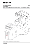
Austausch der Schaltstücke für 3WN1 0…3WN1 2 / 3WN5 0
…3WN5 2, Fig. 1
Replacing contacts for 3WN1 0…3WN1 2 / 3WN5 0…3WN5 2,
Fig. 1
- Lichtbogenkammern gemäß Betriebsanleitung 3ZX18120WN15-0AN0 / 9239 9500 1743, Pkt. 13.4 entfernen
- Isolierwände zwischen den Schaltpolen entfernen (Werkzeugzugänglichkeit). Siehe hierzu Fig.3 mit Hinweisen
- Remove arc chutes as described in Operating Instructions
3ZX1812-0WN15-0AN0 / 9239 9500 1743, 13.4
- Remove the barriers between the pole assemblies (providing
access for tools). See also Fig. 3 with notes
feste Kontaktseite
Fixed contact side
4
1 11 6
2
bewegbare Kontaktseite
Moving contact side
5
3
8
7
10
9
6
3
20
1
Fig. 1
2
4
1 Satz Lichtbogenschaltstücke für einen Pol des
3WN1 0…3WN1 2 / 3WN5 0 …3WN5 2
Bestell-Nr.: 3WY31 12-2AA00
5
1 Set of contacts for one pole assemby of
3WN1 0…3WN1 2 / 3WN5 0 …3WN5 2
Order No.: 3WY31 12-2AA00
Alle Rechte vorbehalten. All rights reserved. Tous droits réservés. Nos reservamos todos los derechos.
© Siemens AG 1989
1
1.
1.
Leistungsschalter mit Unterspannungsauslöser 'F3'
Circuit-breaker with undervoltage release F3
1.1 Bei Leistungsschaltern mit Unterspannungsauslöser 'F3'
den Auslöser mit Hilfe des beigelegten roten Schlüssels
mechanisch in seine Betriebsstellung bringen und dort
blockieren.
1.1 On circuit-breakers with undervoltage release F3 the release
must be brought mechanically with the aid of the supplied
red key into its service position and blocked there.
1.2 Fig. 2
Dazu den Festeinbauschalter auf zwei Abstandsstücke
(17) (Freiraum unterhalb des Schalters ca.100 mm) stellen.
Den Einschubschalter in Wartungsstellung bringen.
1.2 Fig. 2
To do this, place the fixed-mounted circuit-breaker on two
spacers (17) (free space below the breaker approx. 100
mm).
1.3 Fig. 2
Das Blockieren des 'F3' wird erreicht, indem der rote
Schlüssel (20) von unten durch ein Schlüsseloch im unteren
Querträger (18) des Schalters (Bart (19) des Schlüssels
muß nach rechts zeigen und parallel zur Vorderkante (16)
des Schalters stehen) bis Anschlag gesteckt wird und
durch Drehen einer 3/4 Umdrehung entgegen dem
Uhrzeigersinn in Blockierposition gebracht wird.
1.3 Fig. 2
To block the F3, insert the red key (20) from below through
the keyhole in the lower cross-support (18) (bit (19) of key
must point to the right and be parallel to the front edge (16)
of the breaker) as far as the stop and turn it 3/4 of the way
anti-clockwise (into the blocking position).
2.
2.
Ausbau Schaltstücke
Removing contacts
2.1 Feste Kontaktseite
Zuerst festes Schaltstück (1) einschl. Lichtbogenhörner (2)
ausbauen. Hierzu 2 Zylinderschrauben (3) M8 x 35 lösen.
Empfohlenens Werkzeug:
– Drehmomentenschlüssel 7452 FK
Bestell-Nr. 171 557
– Einsatz SW 6
Bestell-Nr. 176 109
der Fa. Belzer -Dowidat, Hastenerstr.4,
D - 42349 Wuppertal
2.1 Fixed contact side
First of all remove fixed contact (1) including arcing horns
(2). To do this, undo two M( x 35 cheese head screws (3).
Tools recommended:
– Torque wrench 7452 FK
Order No. 171 557
– Insert SW 6
Order No. 176 109
from Fa. Belzer -Dowidat, Hastenerstr.4,
D - 42349 Wuppertal, Federal Republic of Germany
2.2 Bewegbare Kontaktseite
2.2 Moving contact side
Bewegbare Schaltstücke (4) einschließlich Lichtbogenhörner (5) ausbauen. Hierzu 2 Senkschrauben ( 6) M8 x 30
lösen (Sechskantmuttern) (7) an der Rückseite der Schalthebel sind unverlierbar festgesetzt und sollen nicht gelöst
werden).
Empfohlenens Werkzeug wie unter 2.1, jedoch statt Einsatz
SW 6:
– Bit SW 5
Bestell-Nr. 114 717
– Bit-Halter 7452-5
Bestell-Nr. 170 569
3.
Remove moving contacts (4) including arcing horns (5). To
do this, undo two M8 x 30 countersunk screws (6). (The
hexagonal nuts (7) are fixed at the rear of the operating
lever and must not be removed).
Tools recommended are as under 2.1, except instead of
insert SW 6:
– Bit SW 5
Order No. 114 717
– Bit holder 7452-5
Order No. 170 569
Einbau Schaltstücke
3.
Fitting contacts
3.1 Zuerst bewegbare Schaltstücke (4) einschließlich Lichtbogenhörner (5) einbauen. Hierzu 2 Senkschrauben (6) M8
x 30 festziehen. Dabei auf Lage der Lichtbogenhörner
zwischen Stromband (10) und Schaltstückträger (11) achten.
Anziehdrehmoment : 16…18 Nm
Werkzeug: wie unter 2.2
3.1 First fit moving contacts (4) including arcing horns (5). To do
this, tighten two M8 x 30 countersunk screws (6). Pay
attention to the position of the arcing horns (5) between
flexible connector (10) and contact carrier (11).
Tightening torque : 16…18 Nm
Tools: as under 2.2
3.2 Feste Schaltstücke (1) einschließlich Lichtbogenhörner (2)
einbauen. Hierzu 2 Zylinderschrauben (3) M8 x 35 festziehen.
Dabei beachten:
– Schaltstück (1) muß fest an Isolierstoffblock (9) anliegen.
Siehe waagerechter Pfeil.
– Butzen der Lichtbogenhörner (2) müssen in entsprechenden
Bohrungen der Stromschienen (8) stecken. Siehe senkrechten Pfeil.
Anziehdrehmoment: 22…25 Nm
Werkzeug: wie unter 2.1
3.2 Fit fixed contacts (1) including arcing horns (2). To do this,
tighen two M8 x 35 cheese head screws (3).
–
–
Note:
Contact (1) must be firmly up against insulating block (9).
See horizontal arrow.
The bulges of the arcing horns (2) must fit in the
corresponding holes in the connections (8). See vertical
arrow.
Tightening torque: 22…25 Nm
Tools: as under 2.1
Blockierposition
Blocking position
Fig. 2
17
Untersicht Z
Underside view Z
17
16
>100
18
17
2
17
20
19
20
4.
Hinweise für Aus- und Einbau der Isolierwände (12),
Fig.3
– Isolierwand (12) in Pfeilrichtung aus- und einbauen.
4.
– Beim Einbau Isolierwand (12) hinter Schild (13) bei „a"
einfädeln.
– In eingebauter Stellung muß Isolierwand (12) bei „b" und
„c" in Rillenführung von Isolierstoffblock (9) stecken.
– Abschottung (14) muß in Rille „d" stecken.
– Dichtungsmasse (15) beim Aus- und Einbau nicht
entfernen.
Notes on removing and fitting the insulating panels
(12), Fig. 3
– Remove and fit insulating panel (12) in the direction
indicated by the arrow..
– When fitting the panel (12), it must be threaded behind
plate (13) at "a".
– When fitted, the insulating panel (12) must be located in the
grooved guide of the moulded-plastic block (9) at "b" and "c".
– Barrier (14) must rest in groove "d".
– The sealing compound (15) must not be removed when
withdrawing and fitting the panels.
15
d
12
15
14
9
b
a
c
Fig. 3
13
5.
Achtung!
Nach dem Austausch der Schaltstücke muß der verwendete
Schlüssel (20) wieder entfernt werden.
Français
5.
Caution!
After replacement of the contacts, the key (20) must be
removed.
Español
Danger!
¡Atención!
Tension électrique dangereuse!
¡Tensión peligrosa!
Avant le début des travaux
Antes de iniciar los trabajos
mettre l'appareil hors tension
dejar el aparato sin tensión
et le condamner dans cette position.
Installation et montage uniquement par des personnes
qualifiées.
N'opérer que lorsque la commande à accccumulation
d'énergie ou à manœuvre indépendante est désarmée.
Voir à ce sujet les paragraphes 13.1 et 13.2 des instructions de service 9500.
Le non-respects de ces règles de sécurité peut entraîner
la mort, des lésions corporelles graves ou des dégats
matériel importants.
y asegurarlo contra la reconexión.
Encargar solo a personal calificado del montaje y la
instalación.
Solo debe trabajarse cuando el accionamiento mediante
acumulador o el accionamiento de acción brusa están
relajados. Véanse las instrucciones de servicio 9500,
puntos 13.1 y 13.2.
La no observancia puede conducir a la muerte, graves
lesiones personales y a considerables daños materiales.
- Déposer les chambres de soufflage en suivant les instructions
3ZX1812-0WN15-0AN0 / 9239 9500 1743 paragrahe 13.4
- Retirer les parois isolantes entre pôles du disjoncteur pour
permettre l'accès des outils (voir fig. 3 et point 4. "Instructions
de pose et de dépose des parois isolantes")
- Retirar las cámaras de extinción de acuerdo con las
instrucciones de servicio 3ZX1812-0WN15-0AN0 / 9239 9500
1743, punto 13.4.
- Retirar durante los trabajos de mantenimiento las placas
aislantes que separan los polos (para poder acceder con las
herramientas). A ese respecto, véanse la figura 3 y las
indicaciones correspondientes.
3
contact fixe
lado de los contactos fijos
contact mobile
Lado de los contactos móviles
4
1 11 6
2
5
3
8
7
10
9
6
3
20
1
Fig. 1
2
5
4
1 jeu de contacts pour un pôle de disjoncteur
3WN1 0 à 3WN1 2 / 3WN5 0 à 3WN5 2
n° de réf.: 3WY31 12-2AA00
1 juego de contactos para un polo del
3WN1 0…3WN1 2 / 3WN5 0 …3WN5 2
N° de pedido: 3WY31 12-2AA00
1.
1.
Disjoncteur avec déclencheur à minimum de tension 'F3'
Interruptor de potencia con disparador de minima
tensión 'F3'
1.1 Sur les disjoncteurs avec déclencheur à minimum de
tension 'F3', la clé rouge jointe doit être utilisée pour amener
le déclencheur en position de service et l'y bloquer.
1.1 En los interruptores de potencia con disparadores de
minima tensión 'F3' hay que situar mecánicamente el
disparador en su posicón de servicio y bloquearlo en ella
utilizando la llave roja suministrada.
1.2 Fig. 2
Pour ce faire, les disjoncteurs fixes doivent être posés sur
deux supports (17) (distance libre sous le disjoncteur env.
100 mm ). Les disjoncteurs débrochables sont amenés en
position d'entretien.
1.2 Fig. 2
Para ello, el interruptor de montaje fijo tiene que ajustarse
a dos tramos distanciadores (17) (espacio libre por debajo
del interruptor unos 100 mm). El interruptor desplazable se
situará en la posición de mantenimiento.
1.3 Fig. 2
Pour bloquer le déclencheur 'F3' en position de service,
introduire la clé rouge (20) par le bas dans la serrure de la
traverse inférieure (18) du disjoncteur, et l'enfoncer jusqu'a
la butée (le panneton (19) doit être parallèle à l'arête avant
(16) du disjoncteur et être orienté vers la droite). Tourner
ensuite la clé 3/4 de tour vers la gauche.
1.3 Fig. 2
El interruptor 'F3' se bloquea introduciendo la llave roja (20)
desde la parte inferior en el agujero del travesaño inferior
(18) del interrupor (el paletón (19) de la llave tiene que estar
dirigido hacia la derecha y situado paralelamente al borde
anterior (16) del interruptor) y, al llegar al tope girándole tres
cuartos de vuelta en sentido antihorario para llegar a la
posición de bloqueo.
2.
Dépose des contacts
2.1 Contacts fixe
Déposer d'abord le contact fixe (1), y compris les cornes
d'arc (5), en dévissant 2 vis à tête cylindrique (3) M8 x 35.
Outillage conseillé:
– clé dynamométrique 7452 FK
n° de réf. 171 557
– douille, ouverture 6 n° de réf. 176 109
des Ets. Belzer -Dowidat, Hastenerstr.4,
D - 42349 Wuppertal (R.F.A.)
2.2 Contacts mobiles
Déposer les contacts mobiles (4), y compris les cornes
d'arc (5), en dévissant 2 vis à tête fraisée (6) M8 x 30 (les
écrous à six pans (7) situés à l'arriére des leviers de
manœuvre sont imperdables; il ne faut pas les dévisser).
Outillage conseillé: comme sous 2.1, mais au lieu de la
douille ouverture 6:
– "bit", ouverture 5
n° de réf. 114 717
– porte- "bit" 7452-5
n° de réf. 170 569
4
2.
Desmontaje de los contactos móviles
2.1 Lado de los contactos móviles
Desmontar primero el contacto fijo (1) incluyendo los
explosores (2). Para ello, soltar los 2 tornillos de cabeza
cilíndrica (3) M8 x 35.:
Herramientas recomendadas:
– Llave dinamométrica 7452 FK
N° de pedido: 171 557
– Copa n° 6
N° de pedido: 176 109
de la empresa Fa. Belzer -Dowidat, Hastenerstr.4,
D - 42349 Wuppertal, Alemania
2.2 Lado de los contactos móviles
Desmontar los contactos móviles (4) incluyendo los
explosores (5). Para ello soltar los 2 tornillos de cabeza
avellanada (6) M8 x30 (las tuercas hexagonales (7) de la
parte posterior de la palanca de maniobra son imperdibles
y no deben soltarse).
Herramientas recomendadas: las indicadas bajo 2.1, pero
en vez de la copa n° 6:
– Copa con destornillador n° 5 N° de pedido: 114 717
– Adaptador para copa con destornillador 7452-5
N° de pedido: 170 569
3.
Pose des contacts
3.
3.1 Poser d'abord le contacts mobiles (4), y compris les cornes
d'arc (5), en serrant 2 vis à tête fraisée (6) M8 x 30. Faire
attention à la position des cornes d'arc (5) entre la tresse
(10) et le porte-contact (11).
Couple de serrage: : 16 à 18 Nm
Outillage: comme sous 2.2
3.2 Poser les contacts fixes (1), y compris les cornes d'arc (2),
en serrant 2 vis à tête cylindrique (3) M8 x 35.
Observer ce qui suit:
– le contact (1) doit s'appliquer fortement au bloc en matiére
isolante (9); voir la flèche horizontale
– les macarons des cornes d'arc (2) doivent s'engager dans
les perçages correspondants des barres de courant (8);
voir flèche verticale
Couple de serrage: 22 à 25 Nm
Outillage: comme sous 2.1
Montaje de los contactos
3.1 Montar primero los contactos móviles (4) incluyendo los
explosores (5). Para ello apretar los 2 tornillos de cabeza
avellanada (6) M8 x 30. Al hacerlo presta atención a que los
explosores (5) estén en la posición correcta entre el
conductor flexible (10) y el porta-contactos (11).
Par de apriete: 16…18 Nm
Herramientas: las indicadas bajo 2.2
3.2 Montar el contacto fijo (1) incluyendo los explosores (2). Para
ello apretar los 2 tornillos de cabeza cilíndrica (3) M8 x 35.
Al hacerlo prestar atención a que:
– El contacto fijo (1) quede apretado contra el bloque aislante
(9). Véase la flecha horizontal.
– Los pivotes de los explosores (2) estén encajados en los
taladros correspondientes de las barras conductoras (8).
Véase la flecha vertical.
Par de apriete: 22…25 Nm
Herramientas: las indicadas bajo 2.1
Position de bloquage
Posici´0n de bloqueo
17
Vue de dessous Z
Vista inferior Z
17
16
18
20
>100
19
Fig. 2
4.
17
20
17
Instructions de pose et de dépose des parois isolantes
(12), fig. 3
– La pose et la dépose des parois isolantes (12) s'effectuent
dans le sens des flèches.
– Lors du montage, la paroi isolante (12) doit être introduite
en "a" derrière le plaque (13).
– En position montée, la paroi isolante (12) doit être emboîtée
en "b" et en „c" dans la rainure du bloc isolant (9).
– La cloison (14) doit venir se fixer dans la rainure "d".
– Le mastic d'étanchéité (15) ne doit pas être enlevé lors
de la pose ou de la dépose.
4.
Indicaciones para desmontar y montar las placas
aislantes (12), figura 3
– Desmontar y montar la placa aislante (12) en el sentido
de la flecha.
– Al montar, la placa aislante (12) debe pasarse detrás de
la pantalla (13) por "a".
– Una vez montada, la placa aislante (12) debe quedar
insertada por "b" y "c" en la ranura del bloque aislante (9).
– El tabique (14) ha de estar insertado en la ranura "d".
– La masa hermetizante (15) no debe retirarse al desmontar
o montar.
15
d
12
15
14
Fig. 3
b
a
9
c
13
5.
Important!
La clé (20) doit être retirée une fois les
contacts remplacés.
5.
¡Atención!
Después de cambiar las piezas de contacto
hay que volver a sacar la llave (20).
5
Herausgegeben von
Bereich Energieübertragung und -verteilung
Schaltwerk Berlin
Published by the
Power Transmission and Distribution Group
Schaltwerk Berlin
D - 13623 Berlin
D - 13623 Berlin
Federal Republic of Germany
Änderungen vorbehalten
Subject to change
Edité par
Division Transport et distribution de l'énergie
Schaltwerk Berlin
Editado por el
Grupo Transporte y Distribución de Energía
Schaltwerk Berlin
D - 13623 Berlin
R.F.A.
D - 13623 Berlin
Alemania
Sous réserve de modifications
Sujeto a modificaciones
6Siemens Aktiengesellschaft
Bestell-Nr./Order No./N° de ref./Referencia: 3ZX1812-0WY31-2AU0 / 9239 9566 175
Bestell-Ort/Place of Order/à commander à/pedidos a: SW PVZ Berlin
Printed in the Federal Republic of Germany
AG 12.94 0.5 SW De-En-Fr-Sp