1
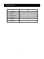
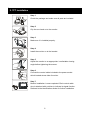
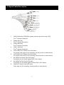
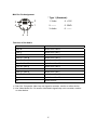
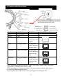
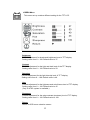
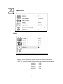
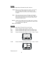
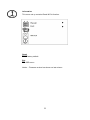
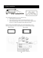
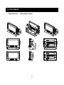
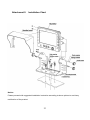
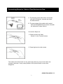
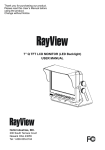
Thank you for purchasing our product.
Please read this User’s Manual before
using the product.
Change without Notice
AWT07MLED
7” Q TFT LCD MONITOR (LED Backlighted)
USER MANUAL
e -4
SAFETY PRECAUTIONS
Federal Communications Commission (FCC) Statement
This Equipment has been tested and found to comply with the limits for a Class
B digital device, pursuant to Part 15 of the FCC rules. These limits are
designed to provide reasonable protection against harmful interference in a
residential installation. This equipment generates, uses and can radiate radio
frequency
energy and, if not installed and used in accordance with the instructions, may
cause harmful interference to radio communications. However, there is no
guarantee that interference will not occur in a particular installation. If this
equipment does cause harmful interference to radio or television reception,
which can be determined by turning the equipment off and on, the user is
encouraged to try to correct the interference by one or more of the following
measures:
-
Reorient or relocate the receiving antenna.
Increase the separation between the equipment and receiver.
Connect the equipment into an outlet on a circuit different from that
to which the receiver is connected.
z
Consult the dealer or an experienced radio / TV technician for help.
You are cautioned that changes or modifications not expressly approved by
the party responsible for compliance could void your authority to operate the
equipment.
This device complies with Part 15 of the FCC Rules.
Operation is subject to the
following two conditions:
(1) This device may not cause harmful interference and,
(2) This device must accept any interference received, including interference
that may cause undesired operation
2
TABLE OF CONTENT
Safety Precaution.………………………....…………………………………………..........2
Table of Content.….………………………………………………………………………3
Features….………………………………………………………………………………...4
1.
Package Contents…….………………………………………………………………..5
2.
TFT Installation……………………………………………….…………………………6
3.
Signal Cable Description……..………………………………….…………………..7
4.
Control Cable Description……..…………………………………….……………….9
5.
Front Panel Control.……………………………………………………..………… 10
Main OSD Menu…….........……………………………………………….………11
Screen Menu……………………………………………………………………...12
Display ……….…………………………………………………………….…13
Camera ...……………………………….…………..................................15
Information...……………………………….…………..................................19
6.
Vehicle Installation ……………………………………….……………………..20
7.
Specification…..………………………………………..……………………….21
8.
Attachment…..……………………………………………….……………………22
3
FEATURE
z
Advanced OSD Menu for easy use
z
Support up to 4 CCD Camera inputs (Mini din connector)
z
Extra RCA input for multimedia while parking (VCD, DVD, Game device)
z
Provide 2 Video / 1 Audio Signal Output (Live Out)
z
Support Single / Dual / Triple / Quad Screen (Cam Out)
z
Signal Trigger for Side / Rear View
z
Auto Day & Night Control via Photo Diode Sensor
z
Auto Detection for NTSC / PAL System
z
OSD Control for Individual Normal / Mirror Camera Image for every camera
z
Auto power on when users are making left turn or right turn even reverse
z
Able to select CAM A / B/C / R’s monitoring screen
z
Supported 9.6V~32V Car power system working
z
Professional Metal Case with Anti Shocking Design
4
1. Package Contents
Item
Qty.
1.
7” LCD Monitor
1
2.
Sun-Hood
1
3.
Mounting Bracket
1
4.
Accessories
1
5.
Control Cable
1
6.
User Manual
1
5
2. TFT Installation
Step 1
Check the package and make sure all parts are included.
Step 2
Clip the sun-hood on to the monitor.
Step 3
Make sure it is installed properly.
Step 4
Install the monitor on to the bracket.
Step 5
Adjust the monitor to an appropriate / comfortable viewing
angle before tightening the screws.
Step 6
Connect the control cable included to the power socket
which located at rear side of monitor.
Step 7
Monitor installation is now completed. Each control cable
wire is attached with a sticker to indicate its signal function.
Referred to the identification sticker for further installation.
6
3. Signal Cable Description
1.
CAM R (Mini din) (NTSC/PAL system presume by this car rear CCD)
st
For 1 camera connection
2.
CAM A (Mini din)
nd
For 2 camera connection
3.
CAM B (Mini din)
rd
For 3 camera connection
4.
CAM C (Mini din)
th
For 4 camera connection
5.
LIVE VIDEO OUT (White Color RCA Jack)
On screen video loop out (for recording, second monitor or other device)
6.
LIVE AUDIO OUT (Black Color RCA Jack)
On screen audio loop out (for recording, second monitor or other device)
7.
AV VIDEO IN (Yellow Color RCA Jack)
Connection for any Video signal (DVD, VCD, Game)
8.
AV AUDIO IN (Red Color RCA Jack)
9.
CAM OUT (Green Color RCA Jack)
Connection for any Audio signal (such as DVD, VCD, Game)
Video loop out (for recording, second monitor or other device)
7
Mini Din Pin Assignment
* Type 1 (Standard):
2
1
3
4
6
1. Video
4. +12V
2. -------
5. GND
3. Audio
6. -------
5
Function of the Audio
Cam A
Audio from Cam A
Cam B
Audio from Cam B
Cam C
Audio from Cam C
Cam R
Audio from Cam R
Cam A + Cam B
Audio from Cam A
Cam C+ Cam R
Audio from Cam R
Cam A+ Cam R
Audio from Cam R
Cam R+ Cam B
Audio from Cam R
Cam A + Cam C
Audio from Cam A
Cam C+ Cam B
Audio from Cam C
Cam R / Cam AB
Audio from Cam R
Quad
Audio from Cam R
AV
Audio from AV
※ Cam Out: Composite video loop out signal to recorder, monitor or other device.
※ Live Video/Audio Out: On screen video/audio signal loop out to recorder, monitor
or other device.
8
4. Control cable Description
Don’t connect the red wire (power wire) of this product
directly to the battery. Connect the red wire of this product
to the ACC of the ignition key switch. Failure to do so may
result in permanent damage of the product.
WIRE COLOR
FUNCTION
RED
ACC POWER
BLACK
GND
WHITE
SW Control
REMARK
ON SCREEN VIEW
Active Power
Level Connect to
CAM C
BLUE
Reverse Control
Active Power
Level Connect to
Reverse Light
ORANGE
Right Turn Control
CAM R
M enu
Ju mp
S our ce
P ower
Active Power
Level Connect to
CAM R
CAM B
Direction Light
(R)
YELLOW
Left Turn Control
Active Power
Level Connect to
CAM A
CAM R
Direction Light
(L)
1. The control cable sequence: Reverse > Right / Left / CAM C when Priority is ON. Right
/ Left / CAM C > Reverse when Priority is OFF.
2. With car power is on, the monitor power is off, when making a reverse / right / left turn,
the monitor will display default screen.
3. You may push the “JUMP” button under event trigger when Priority is OFF.
9
5. Front Panel Control
POWER
Press the power button to activate the monitor or to keep the monitor
under stand by mode (In Red Led).
SELECT
With power on, press this button to select image sequence as below~
AVÆCAM A+BÆCAM C+RÆCAM A+RÆCAM R+BÆCAM A+CÆ
CAM C+BÆCAM R/ABÆCAM R+ABÆCAM AÆCAM BÆCAM CÆ
CAM R ÆAV……..
Prerequisite:Display menu ÆPriority option is “ON”
JUMP
Press this button to display defined camera input, user can select
QUADÆSEQÆCAM A+BÆCAM C+RÆCAM A+RÆCAM R+BÆ
CAM A+CÆCAM C+BÆCAM R/AB ÆCAM R+AB ÆCAM A ÆCAM B
CAM CÆCAM R via OSD as default value.
Prerequisite:Display menu ÆPriority option is “ON”
MENU
This encoder switch provides the following function:
1. Activate OSD menu: Press the Menu switch to activate the OSD menu.
After the OSD menu is activated, in case users does not proceed for
further set up, the OSD menu will then automatically turn off within
20 seconds.
2. Enter Function: Press the encoder switch to act as “Enter” function
under the OSD menu.
3. Volume Value: Exit the OSD menu, user can turn this switch
left or right to adjust the volume value.
10
OSD Menu
1.
Press the MENU button to enter to the OSD Menu
2.
Turn the MENU button left or right to select the setting you
wish to proceed. The color of the content will turns YELLOW
to identify your selection. Turn the MENU button left or right to
adjust your setting value.
3.
Press the MENU button once back to submenu and then press menu
button again in order to return to OSD menu.
Enter to Main menu:
11
SCREEN Menu
This menu set up contains different setting for the TFT LCD.
Brightness
Provide adjustment for shade and brightness level of TFT display.
Setting value from 0 ~ 100. Default value is 37.
Contrast
Provide adjustment for the light and dark level of the TFT display.
Setting value from 0 ~ 100. Default value is 50.
Saturation
Provide adjustment for the light intensity level of TFT display.
Setting value from 0 ~ 100. Default value is 40.
Hue
Provide adjustment for the lightness and colorfulness level of TFT display.
Setting value from 0 ~ 100. Default value is 45.
(Only in NTSC system is available.)
Sharpness
Provide adjustment for the edge contrast (acutance) level of TFT display.
Setting value from 0 ~ 100. Default value is 100.
Return
Return to OSD menu selection screen.
12
DISPLAY Menu
This menu set up contains the on screen identification
and the activation of the distance gauge.
Auto Day&Night
Select “ON” to activate the auto day & night function or “OFF” to
deactivate it. Default value is OFF.
Display
Select “ON” to show the SELECT of video input title on screen or “OFF”
to keep it invisible. Default value is ON.
Distance Gauge
Set the distance gauge “ON” to show the distance gauge on screen while
reserving or “OFF” to deactivate. Default value is ON.
(This “DISTANCE GAUGE” is for user’s reference only)
OSD Lock
This function provides protection when an unauthorized person tries to
access the OSD settings. JUMP and SELECT key press simultaneously
for over 5 seconds to unlock. Default value is OFF.
※Users must turn on LCD in order to run unlock process. All function
buttons are still working during OSD Menu lock up period.
13
PRIORITY
If Priority is ON
a. Press SOURCE button to select image sequence as below~
AVÆCAM A+BÆCAM C+RÆCAM A+RÆCAM R+BÆCAM A+CÆ
CAM C+BÆCAM R/ABÆCAM R+ABÆCAM AÆCAM BÆCAM CÆ
CAM R ÆAV…….
b. Triggered mode priority: Reverse > Right/Left / CAM C
c. JUMP mode: QUAD
d. OSD Lock mode: OFF
If Priority is OFF
a. Press SOURCE button to select image sequence is as below~
AVÆ CAM AÆCAM BÆCAM CÆCAM R ÆAV……..
b. Triggered mode priority: Right/Left/CAM C > Reverse
c. JUMP mode: CAM R
d. OSD Lock mode: ON
Default value is “ON”.
Notice:When you choose “OFF” mode also enable OSD Lock function.
REVERSE MODE
When reversing select LCD profile ratio 4:3 the display show in size
4:3(default), select LCD profile ratio 16:9 the display show in size 16:9
Return
Return to OSD menu selection screen.
14
CAMERA Menu
This menu set up contains the on Camera and Jump setting.
Mirror
Select “ON” to activate the mirror function for different cameras or
“OFF” for a normal image. Default values are following below setting.
CAM A
“OFF”
CAM B
“OFF”
CAM C
CAM R
“OFF”
“ON”
15
Dir Image
The screen image setting of this panel during left / right turn:
TRIPLE: When you are making a right turn or left turn, the screen of
panel will display triple images for left hand side, right
hand side and rear view when you are making a right turn
or left turn.
DUAL:
With proper wiring, the screen will display dual image for
both rear and right hand side view when making a right turn.
While left turning, the screen will show dual image for both
rear and left hand side view.
SINGLE: Screen of touch panel shows only single picture on direction
turn. The screen will show only left side view on left turn and
only right side view on right turn.
Default value is SINGLE.
Rear Setup
The screen image setting of this panel during reverse gear:
R:
Screen will display single image for Cam R only.
R+A:
Screen will display dual image for both Cam R and Cam A.
R+B:
Screen will display dual image for both Cam R and Cam B.
R/AB
Screen will display triple image from Cam R、Cam A、Cam B.
CAM R
CAM A
R+AB
CAM B
Screen will display triple image from Cam R、Cam A、Cam B.
CAM A
CAM R
CAM B
Menu
Default value is R.
16
Jump
By pressing this button, the driver will be able to obtain the image
selected under this setting.
QUAD
Obtain image from all camera input in quad picture
while pressing the JUMP button and press again to
return the default screen.
SEQ.
Corresponding with “SEQ. Timer Step” setting to
jump channel by time sequence.
CAM A
Obtain image from camera A while pressing the
JUMP button and press again to return the default
screen.
CAM B
Obtain image from camera B while pressing the
JUMP button and press again to return the default
screen.
CAM C
Obtain image from camera C while pressing the
JUMP button and press again to return the default
screen.
CAM R
Obtain image from camera R while pressing the
JUMP button and press again to return the default
screen.
CAM A+B
Obtain image from camera A+B in dual picture while
pressing the JUMP button and press again to return
the default screen.
CAM C+R
Obtain image from camera C+R in dual picture while
pressing the JUMP button and press again to return
the default screen.
CAM A+R
Obtain image from camera A+R in dual picture while
pressing the JUMP button and press again to return
the default screen.
CAM R+B
Obtain image from camera R+B in dual picture while
pressing the JUMP button and press again to return
the default screen.
CAM A+C
Obtain image from camera A+C in dual picture while
pressing the JUMP button and press again to return
the default screen.
CAM C+B
Obtain image from camera C+B in dual picture while
pressing the JUMP button and press again to return
the default screen.
CAM R/AB
Obtain image from camera R+A+B in triple picture
while pressing the JUMP button and press again to
return the default screen.
CAM R+AB
Obtain image from camera R+A+B in triple picture
while pressing the JUMP button and press again to
return the default screen.
Default value is QUAD.
17
Cam Out
Composite video loop out to recorder, monitor or other device.
QUAD
Recording or viewing from the output device in quad
mode
CAM A
Recording or viewing from the output device for CAM
A image
CAM B
Recording or viewing from the output device for CAM
B image
CAM C
Recording or viewing from the output device for CAM
C image
CAM R
Recording or viewing from the output device for CAM
R image
Default value is QUAD.
SEQ Time Step
Select Cam A/B/C/R switching time setting value from 02~100
Default value is “02”
Return
Return to OSD menu selection screen.
18
Information
This menu set up contains Recall & Exit function.
Recall
Recall factory default.
Exit
Exit OSD menu.
Notice:Firmware version has shown on last column.
19
6. Vehicle Installation
C a mera
Green
Yellow
1M
0M
1M
Red
2M
Yellow
Red
3M
Green
(This “ DISTANCE GAUGE” is for user’s reference only)
a.
Install Camera R (for rear view)
b.
Use a measuring tool to mark out the distance behind the vehicle.
c.
Adjust the viewing angle of the camera so that the distance gauge shown
from the TFT match to the distance marks behind the vehicle.
Switch to Rear view with SELECT button, the screen always display on 16:9
While rear viewing, the screen always display on 4:3 to correct size percentage
SELECT button:
Rear viewing:
16
4
3
9
20
7. Specification
Screen size
7 Inch Touch Panel ( diagonal )
Active area
154.08(H) x 86.58(V)
Pixel configuration
0.107 x 0.370
Resolution
1440(W) x 234 (H)
Viewing angle
UP:40° / Down:60°
/ Left: 60°
/ Right:60°
Power source:
DC9.6V ~DC32V
Contrast ratio
300:1
※
2
Brightness
450 cd/m ※
AV Video In
Connector
RCA
Input Signal
1Vpp
Impedance
75 Ohms
Camera MINI DIN In
Connector
6 PIN MINI DIN (Standard)
Input video signal level
1Vpp
Impedance
75 Ohms
Input audio signal level
1Vpp
Power output for camera DC12V 350mA
AV Audio In
Connector
RCA
Input video signal level
1Vpp
Impedance
1K Ohms
Live Video Out
Connector
RCA
Input signal level
1Vpp
Impedance
75 Ohms
CAM OUT
Connector
RCA
Input signal level
1Vpp
Impedance
75 Ohms
LIVE Audio Out
Connector
RCA
Input signal level
1Vpp
Impedance
1K Ohms
Dimension
WxHxD:
192 x140.5 x 51.8mm
Weight
N.W./G.W.: 2kg/ 2.28kg
Environmental:
Operation temperature
-10℃~70℃
Storage temperature
-30℃~80℃
Humidity
20%-80%
※The brightness and contrast ratio specifications are from panel specification.
Design and Specifications are subject to change without notice.
A1.6
21
8. ATTACHMENT
Attachment 1: Dimension Chart
22
Attachment 2: Installation Chart
Notice:
Please proceed with suggested installation instruction according to above picture to avoid any
malfunction of the product.
23
Connecting Steps for Cable of Two-Sections-in-One.
A. The first part of the cable which connected
with the LCD Monitor, herewith we called
the Male Section
B. The second part of the cable which ended
with the RCA/MINI DIN connectors, herewith
we called the Female Section.
Connection Steps are:
1. Please connect the “Male
Section” to the “Female Section.
2. Please tight up the side screws.
The Cable should be stored in a dry place and please try to avoid the water and
humidity, otherwise, it may cause problem of the product itself or even more
dangerous.
85-ML072Q-A003G - D
24