1
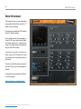
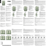
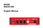
TC Electronic TonePrint Editor Manual Table of contents About this manual 1 Welcome! So… what’s in a TonePrint? . . . . . . . . . . . . . . . TonePrint Editor’s resumé. . . . . . . . . . . . . . . . . What you will need . . . . . . . . . . . . . . . . . . . . . . 2 2 2 2 Getting started Ready…. . . . . . . . . . . . . . . . . . . . . . . . . . . . . . Set…. . . . . . . . . . . . . . . . . . . . . . . . . . . . . . . . . TonePrint! . . . . . . . . . . . . . . . . . . . . . . . . . . . . . Precautions: Don’t lose that TonePrint! . . . . . . . . . . . . . . . . . Different pedals, different parameters. . . . . . . . Multiple TonePrint pedals – one editor. . . . . . . Pedal serial and software version information . . . . . . . . . . . . . . . . . . . . . . Your sound: There’s a template for that!. . . . . . . . . . . . . . . . 3 3 3 3 Using TonePrint Editor Template TonePrint. . . . . . . . . . . . . . . . . . . . . . Returning to template defaults Router section. . . . . . . . . . . . . . . . . . . . . . . . . . Kill Dry parameter Knob Selection section. . . . . . . . . . . . . . . . . . . Assigning parameters to a knob Modifier display. . . . . . . . . . . . . . . . . . . . . . . . . 6 6 6 6 6 6 7 7 Modifier sections 9 Modulation parameters Modulation Type selector . . . . . . . . . . . . . . . . Classic Chorus setting Advanced Chorus setting Classic Flanger setting Advanced Flanger setting 4 4 4 5 5 10 10 10 10 10 10 Vibrato setting TriChorus setting TriChorus Alternative setting TZFlanger (“Through zero”) setting Modulation Active parameter. . . . . . . . . . . . . . Through-Zero-Flanger parameter. . . . . . . . . . Speed parameter. . . . . . . . . . . . . . . . . . . . . . . Depth 1 parameter . . . . . . . . . . . . . . . . . . . . . Depth 2 parameter . . . . . . . . . . . . . . . . . . . . . Depth 3 parameter . . . . . . . . . . . . . . . . . . . . . HiCut parameter . . . . . . . . . . . . . . . . . . . . . . . Mix parameter. . . . . . . . . . . . . . . . . . . . . . . . . Output Level parameter. . . . . . . . . . . . . . . . . Delay Time 1 parameter . . . . . . . . . . . . . . . . . Delay Time 2 parameter . . . . . . . . . . . . . . . . . Delay Time 3 parameter . . . . . . . . . . . . . . . . . Feedback parameter. . . . . . . . . . . . . . . . . . . . Feedback HiCut parameter. . . . . . . . . . . . . . . Vib. Ramp Time parameter. . . . . . . . . . . . . . . 10 10 10 10 10 11 11 11 11 11 11 11 11 11 11 12 12 12 12 Delay parameters Delay Time parameter. . . . . . . . . . . . . . . . . . . Feedback parameter. . . . . . . . . . . . . . . . . . . . Saturation parameter. . . . . . . . . . . . . . . . . . . . FB HiCut (Feedback High-Cut) parameter. . . . . . . . . . . . . . . . . . . . FB LoCut (Feedback Low-Cut) parameter . . . . . . . . . . . . . . . . . . . . Output Level parameter. . . . . . . . . . . . . . . . . Dynamic Delay Sensitivity parameter. . . . . . . . . . . . . . . . . . . . Damping parameter. . . . . . . . . . . . . . . . . . . . . Release Time parameter. . . . . . . . . . . . . . . . . Reverse Delay Time parameter . . . . . . . . . . . 13 13 13 13 13 Reverb parameters Decay parameter. . . . . . . . . . . . . . . . . . . . . . . PreDelayShort parameter. . . . . . . . . . . . . . . . PreDelayLong parameter . . . . . . . . . . . . . . . . Diffuse parameter . . . . . . . . . . . . . . . . . . . . . . LoColor parameter . . . . . . . . . . . . . . . . . . . . . HiColor parameter. . . . . . . . . . . . . . . . . . . . . . HiFactor parameter. . . . . . . . . . . . . . . . . . . . . Mod On/Off parameter . . . . . . . . . . . . . . . . . . Modulation Rate parameter. . . . . . . . . . . . . . . Modulation Depth parameter. . . . . . . . . . . . . . Early parameter. . . . . . . . . . . . . . . . . . . . . . . . Reverb parameter. . . . . . . . . . . . . . . . . . . . . . Dynamix Mode switch. . . . . . . . . . . . . . . . . . . Off setting Positive mode Inverse mode Dynamix Threshold parameter . . . . . . . . . . . . Dynamix Damp parameter . . . . . . . . . . . . . . . Dynamix Attack parameter . . . . . . . . . . . . . . . Dynamix Release parameter. . . . . . . . . . . . . . 15 15 15 15 15 15 15 15 15 15 15 16 16 16 16 16 16 16 16 16 16 Updating TonePrint Editor 17 Getting support 17 13 13 13 14 14 14 a ■ About this manual About this manual This manual will help you learn understanding and operating TonePrint Editor (and all the TC pedals you can control with it). This manual is only available as a PDF download from the TC Electronic website. You can print this manual, but we encourage you to use the PDF version, which has both internal and external hyperlinks. E.g., clicking the blue square ■ in the upper left corner of each page will take you to the table of contents. If you want to jump right in, click into an interface section in the illustration to the right to go directly to the corresponding section of this manual. To get the most from this manual, please read it from start to finish, or you may miss important information. To download the most current version of this manual, visit the web page http://www.tcelectronic.com/support/manuals/ TC Electronic TonePrint Editor ■ Manual for software version 1.0 1 ■Welcome! Welcome! So… what’s in a TonePrint? We should probably start by telling you what TonePrint actually means. TonePrint means… signature effects. These are custom-built versions of classic TC effects, available for our TonePrint pedals. But we’re not talking simple presets here – we’re way past that! TonePrints are custom-tuned sounds, built by the best of the best in modern music from the ground up – with every parameter, knob range and effect value up in the air! We have asked the very best guitarists and bass players to give us their personal take on TC effects as they use them live and in the studio, and they have come up with sounds that truly represent their personality, their sonic DNA. TonePrint Editor’s resumé ■ Use TonePrint Editor to build your own custom version of renowned TC Effects from scratch. ■Enjoy complete control over all effect para meters and effect behavior – it’s your vision, sound. ■ Customize knob functions and knob ranges to suit your needs and sounds. ■ Use an intuitive, slider-based interface. ■Audition your sonic creations in real-time. Make changes on the fly and listen to results immediately. ■ Works with both PC and Mac. ■ Last but not least… TonePrint Editor is absolutely free! What you will need ■A TonePrint-enabled effects pedal. ■An instrument and an amplifier so you can play and listen to your sonic creations. ■A computer running Microsoft Windows or Apple’s OS X (i.e., a Mac). ■ PC requirements: Windows XP (with SP2), Vista, Win 7 or Windows 8 ■ Mac requirements: An Intel-based Mac running OS X version 10.5 or higher ■A USB cable (type A Male to Mini B Male) to connect your computer and your TonePrint-enabled TC product. TC customers have been able to download, use and enjoy these TonePrints for years. But now it’s time for a new chapter. Now it’s your turn to create your very own signature effects. Take a TC pedal, take a TonePrint, take TonePrint Editor – and make it your own. TC Electronic TonePrint Editor ■ Manual for software version 1.0 2 ■ Getting started Getting started Ready… If you haven’t already done so, download the latest TonePrint Editor software from: Set… ■ Set up your TC pedal as you normally would: ■ Connect your instrument to the audio in jack(s) of the pedal, http://www.tcelectronic.com/toneprint-editor/ ■ connect the audio out jack(s) of the pedal to TonePrint Editor software is free. ■ connect the pedal to a power supply. Install TonePrint Editor. ■To install the PC (Windows) version, simply move the .exe file you downloaded to a location on your hard disk. ■ To install the Mac (OS X) version, open the .DMG file you downloaded. From the disk image, copy TonePrint Editor.app to your application folder or any other location where you can easily find it. your amp and ■ Make sure you’ve got a basic sound (and a sound level) you’re comfortable with, with the effect bypassed. ■ Turn the effect on. ■ Connect your pedal to your computer using the type A Male to Mini B Male USB cable. Please note that you can only connect and control one TonePrint-enabled product at a time, even if your computer has multiple USB ports. ■ Using its Type Selector, switch your pedal to the TonePrint slot you want to use. ■ Open TonePrint Editor on your computer. TonePrint! When you have opened TonePrint Editor on your computer with a TonePrint-enabled TC product connected to it, TonePrint Editor should automatically detect the connected device and show you a graphical representation of its parameters on screen. If you see a splash screen saying that you should connect a TonePrint pedal, your pedal has not been detected. Make sure it is powered up and connected to your computer via USB. Once your pedal has been detected, you are ready to create your very own TonePrints. Here is how it basically works: TonePrint Editor exposes the internal parameters of a TonePrint-enabled pedal. Use the on-screen sliders of TonePrint Editor to adjust the effect’s parameters. These sliders allow you to create a customized version of a renowned TC effect that you can call your own. From subtle variations to extreme modifications that will fundamentally alter an effect’s character and behavior: The choice is yours! TC Electronic TonePrint Editor ■ Manual for software version 1.0 3 ■ Getting started Precautions: Don’t lose that TonePrint! When editing TonePrints, there are two things that you should always keep in mind: ■ When you are done editing, always remember to store your TonePrint to the pedal using the “Store to Pedal” button! If you don’t, you will lose your creation when you disconnect the pedal. Different pedals, different parameters Multiple TonePrint pedals – one editor to rule them all With delay and reverb TonePrints, you can also add modulation to the effect. The interface for reverb/delay modulation is the same as for the pedals dedicated to modulation effects. However, please note that no matter how many USB ports your computer has, you can only access one TonePrint-enabled pedal at a time. No two TonePrint-enabled pedals are alike – but different pedal types share certain parameters such as “Speed” and “Depth”. This is why this manual has three parameter-related sections: ■ You can use the knobs on your pedal in real- time, and the parameters will follow on-screen, but whatever you do: Don’t change the Type Selector away from the TonePrint slot, and do not disconnect power while editing without saving. TC Electronic TonePrint Editor ■ ■ The first section covers all modulation-related parameters in TonePrint Editor. ■ The second section covers all parameters re- lated to delay TonePrints. You own more than one TonePrint-enabled pedal? That’s great! Just connect the pedal you want to configure to your computer using a USB cable, and the user interface will update immediately. You can connect and disconnect pedals to your computer via USB even while TonePrint Editor is running. To edit TonePrints and store a TonePrint to a pedal, the pedal must be connected to a power supply. No power is supplied to the pedal via your computer’s USB port. ■ The third section is dedicated to all parameters Manual for software version 1.0 of reverb TonePrints. 4 ■ Getting started Pedal serial and software version information Your sound: There’s a template for that! ■ ■ ■ ■ These templates allow you to load a base TonePrint and customize it instead of starting with a blank slate. These templates are great for sketching out quick ideas, infusing your own concepts, tweaks and preferences. If you are new to effects and sound design, they will also give you an idea of how a typical effect is set up. When a TonePrint-enabled pedal is connected to your computer and you click the small “i” icon in the lower left corner of the TonePrint Editor window, a dialog box will show the following information: Device serial number Device firmware build number TonePrint Editor software version number TonePrint Editor software build number. We know: Going from a handful of knobs on a pedal to a screen full of sliders can be a bit tricky, and you may be intimidated by the idea of creating a TonePrint from scratch. This is why we have provided you with Template TonePrints. Finally, if you got a bit overexcited and you find that you are stuck with a TonePrint that just doesn’t sound or work as it should, a Template TonePrint can be your get-out-of-jail-free card. TC Electronic TonePrint Editor ■ Manual for software version 1.0 5 ■ Using TonePrint Editor Using TonePrint Editor Template TonePrint As described on the previous page, TonePrint Templates are a great way of starting your personal sound creation, as they give you time-proven defaults for all parameters. To recall a template, select it from the menu. Please note that selecting a template will immediately override all changes you might have made to knob assignments, modifier curves and parameter values. Router section Kill Dry parameter Settings: Off/On If you find that you have reached a dead end when editing, you can simply click the Reload button next to the Template menu to reset the currently selected template to its default values. This will reset all knob assignments, modifier curves and parameter values to the defaults stored in this template. ■ In the knob selection section, you can assign different functions to your pedal’s knobs, so they control exactly what you want them to control. Use the Kill Dry parameter to define wether your instrument’s dry, unprocessed signal should pass through the pedal. Setting Kill Dry to On will mute the dry signal of your instrument. This is especially useful for reverse delay effects and vibrato effects – but you may find other, creative uses for this parameter. Returning to template defaults TC Electronic TonePrint Editor Knob Selection section Manual for software version 1.0 But there’s more here than simple 1:1 assignments! You can assign two or even three functions to one knob, allowing you to change multiple parameters by using just one control. This allows for very efficient control and dramatic changes, if this is what you want to achieve. Finally, you can scale and limit the way a knob controls a parameter you have assigned to it. Let’s say that a parameter that you want to control has a range from 0 to 100 %. Turning the respective knob to the minimum position will set the parameter to 0 %, and the maximum position represents 100 %. But what if the “sweet spot” lies between 25 and 50 %? 6 ■ Using TonePrint Editor With TonePrint Editor, you decide what parameter range you want to control, and how the knob’s position should affect it. If you want to, you can even use the knob range left of the center position to go from 0 to 100 % – and then back to 25 % when turning the knob all the way clockwise. Assigning parameters to a knob ■ Start by selecting a knob in the Knob Selection section. The selected knob will be highlighted. ■ Select one of the three yellow, red and blue “LEDs”. The selected LED will be highlighted. ■ Select a parameter you want to control from the drop-down menu to the left of the LED. Modifier display In the upper left part of the TonePrint Editor window is small graphical interface where effect values assigned to the currently selected knob are represented by “peaks” and “valleys”. This display is your key to understanding and controlling the way your pedal’s knobs control effect parameters. ■ Turn the knob to see its current position high- Before you can define the relationship between knob positions and parameter values, you have to select the parameter in the Knob Selection section. As you can see, you can assign up to three parameters to a knob. The currently selected parameter will be highlighted in the display, with the other parameters still visible in the background. Once you have selected a parameter, the modifier curve for that parameter will be shown in the Modifier display. By default, this is a straight line from the parameter’s lowest value in the lower left corner to the maximum value in the upper right corner. lighted in the graphical “Peak Performance” interface. Scaling the selected parameter is described in the next section of this manual. TC Electronic TonePrint Editor ■ Manual for software version 1.0 7 ■ Using TonePrint Editor To modify the curve, you can either drag one of the circle-shaped control points of the modifier curve, or you can select one of the numerical values shown right below the display and enter the desired value manually. As you can set the modifier curve separately for each of the three parameters that each knob can control, you could make a knob on your pedal increase one parameter’s value as you turn it clockwise while decreasing another parameter’s value at the same time. We suggest playing your instrument and turning the currently selected knob to get a better understanding of the way that knobs and modifier curves interact. TC Electronic TonePrint Editor ■ Manual for software version 1.0 8 ■ Modifier sections Modifier sections Use the parameters displayed in the right-handside section of the TonePrint Editor window to set the parameters that define your TonePrint. This is the heart of your TonePrint – the place where you define your sound. Please note that what you are seeing here depends on the type of TonePrint pedal connected. With a modulation-only pedal, you will only see the “Modulation” section. Reverb and delay pedals will also show a Modulation section, as described in “Different pedals, different parameters” (page 4). If you have worked with effect processors (either hardware or software) before, this part of the TonePrint Editor window should look familiar. This is an elegant, slider-based interface with a “what you see is what you get” approach: Change a parameter, and both the display and what you are hearing will immediately reflect the new setting. In the following sections of this manual, we will present and explain the parameters of the three sections: Delay, Reverb, and Modulation. TC Electronic TonePrint Editor ■ Manual for software version 1.0 9 ■ Modulation parameters Modulation parameters Use the parameters in the Modulation part of the TonePrint Editor window to configure the modulation effect. Classic Flanger setting The flanger belongs to the same “family” of modulation effects as the chorus effect. The signal is split, and one of the signals is pitch modulated. The characteristic “flanging” sound occurs when part of the signal is slightly delayed and fed back to the input of the effect algorithm. Experiment with the Feedback parameter to get a feeling for the achievable effects. Use the Modulation Type selector to select between the following types of modulation effects: Classic Chorus setting This is the standard chorus inspired by the le gendary TC Stereo Chorus Flanger. The basic idea of a chorus effect is to split the signal and pitch-modulate one of the signals slightly, and then mix the two signals again. Advanced Chorus setting The Advanced Chorus setting is a variation of the Chorus setting where the parameters defining the chorus effect are tuned slightly differently. TC Electronic TonePrint Editor ■ The TriChorus Alternative setting is a variation of the TriChorus setting where the parameters defining the modulation parameters of the three chorus modules are tuned to produce a wilder and “less controlled” Chorus effect. TZFlanger (“Through zero”) setting Vibrato setting The TZF Mode Flanger emulates the original way of creating a flange effect where two identical pieces of audio material were played back simultaneously on two tape decks and then mixed on a third deck. The “flanging” effect was achieved by slowing down and speeding up the two decks at different times. An essential part of this setup is the unique phase cancellation occurring when the two signals pass each other in time (the “zero point”). As opposed to a chorus effect, no direct signal is combined with the vibrato effect’s pitch-modulated signal. When you set the Modulation Type parameter to TZFlanger, the input signal is split up so that delay line 1 becomes the “dry” part of the signal. This is why you should set the Kill dry parameter to On when setting the Modulation Type parameter to TZFlanger. Advanced Flanger setting Modulation Type selector TriChorus Alternative setting The Advanced Flanger setting is a variation of the Flanger setting where the parameters defining the flanger effect are tuned slightly differently. A vibrato effect modulates the pitch of the incoming signal. The result is similar to the vibrato technique used by vocalists. TriChorus setting The TriChorus is a variation of the regular chorus that uses three stereo chorus modules with various offsets for the Depth, Speed, Phase and Chorus Delay time parameters. The result is a unique, very broad and lush sound. Speed, Depth and Time parameters are identical to those in the standard Chorus. Manual for software version 1.0 Modulation Active parameter Settings: On/Off Use the Modulation Active parameter to switch the modulation effect on or off. This is especially useful for activating the modulation engine when working with delay and reverb TonePrints. However, you also need to set this parameter to On for regular modulation effects. 10 ■ Modulation parameters Through-Zero-Flanger parameter TZFlanger mode, the Depth 2 parameter specifies the intensity of the second flange module. Output Level parameter When you set the Modulation Type parameter to TZFlanger, delay line 1 becomes the “dry” part of the signal. In that case, use the Through-ZeroFlanger parameter to set the level ratio between delay line 1 and delay line 2. The value represents the amplitude of the second waveform modulating the signal. Use the Output Level parameter to set the overall output level for the modulation effect. Depth 3 parameter Delay Time 1 parameter Speed parameter The Depth 3 parameter is only applicable when you have set Modulation Type to TriChorus. Use the Speed parameter to set the speed of the chosen modulation effect. As setting of 1 Hz means that one modulation cycle takes one se cond. In TriChorus mode, the Depth 3 parameter specifies the intensity of the third chorus module. As described earlier, a chorus or flanger is basically a delay being modulated by an LFO. Use the Delay Time 1 parameter to change the length of that delay. A typical chorus uses delay times around 10 ms, while a flanger uses delays around 5 ms. Parameter range: 0 to 1023 Parameter range: 61.5 mHz (Millihertz) to 20 Hz Depth 1 parameter Parameter range: 0 to 100 % The value represents the amplitude of the third waveform modulating the signal. HiCut parameter Parameter range: 0 to 100 % Use the Depth 1 parameter to specify the intensity of the effect. The value represents the amplitude of the waveform modulating the signal. Parameter range: 20 Hz to 20 kHz Parameter range: -100 to 0 dB Parameter range: 0.1 to 50 ms Although this is not how a chorus is normally used, you may enjoy the “slap-back” sound resulting from longer Delay Time values in the 30 to 50 ms range. Delay Time 2 parameter When you have set Modulation Type to TZFlanger, you should set the Depth 1 parameter to a value lower than Depth 2. Use the HiCut parameter to reduce the high-end frequencies in the modulation effect. Try using this parameter if you feel the effect is too dominant in your sound and turning down the Mix or Output Level parameters doesn’t attenuate the effect as intended. Depth 2 parameter Mix parameter The Depth 2 parameter is only applicable when you have set Modulation Type to TriChorus or TZFlanger. Use the Mix parameter to set the relationship between the level of the dry signal and the level of the modulation effect. If you have set Kill dry in the Router section to On, this parameter has no effect. In TriChorus mode, the Delay Time 2 parameter specifies the length of the delay for the second chorus module. Parameter range: 0 to 100 % Parameter range: 0 to 100 % In TriChorus mode, the Depth 2 parameter specifies the intensity of the second chorus module. In TC Electronic TonePrint Editor ■ Manual for software version 1.0 Parameter range: 0.1 to 50 ms The Delay Time 2 parameter is only applicable when you have set Modulation Type to TriChorus or TZFlanger. In TZFlanger mode, the Delay Time 2 parameter specifies the length of the delay for the second flange module. 11 ■ Modulation parameters Delay Time 3 parameter Parameter range: 0.1 to 50 ms The Delay Time 3 parameter is only applicable when you have set Modulation Type to TriChorus. In TriChorus mode, the Delay Time 3 parameter specifies the length of the delay for the third chorus module. Feedback parameter Parameter range: -100 to 100 % Use the feedback parameter to define the amount of the signal that is fed back from the modulation module’s output to its input. Vib. Ramp Time parameter (Shaker Vibrato only) Parameter range: 1 to 5000 ms The Vib(rato) Ramp Time parameter is only available and editable when a Shaker Vibrato pedal is connected. The Vibrato Ramp effect is a subtype of the vibrato effect where the effect is latched – i.e., the effect will only be applied when you press and hold the pedal’s footswitch. The Vibrato Ramp Time parameter sets the time that is required for the vibrato effect to build up. Experiment with the Feedback parameter to get a feeling for the effects you can achieve. Feedback HiCut parameter Parameter range: 20 Hz to 20 kHz Use the Feedback HiCut parameter to attenuate the high-end frequencies of the resonance created with the Feedback parameter. TC Electronic TonePrint Editor ■ Manual for software version 1.0 12 ■ Delay parameters Delay parameters simply turning off the effect until things have settled down again. Use the parameters in the Delay part of the TonePrint Editor window to configure the delay effect. Saturation parameter Parameter range: 0 to 24 dB Use the Saturation parameter to add a bit of signal saturation to your delays. This is recommended if you want to add a touch of “grit” to a TonePrint. Delay Time parameter Parameter range: 0 to 7000 ms Use the Delay Time parameter to set the time between delay repetitions. This is also known as the “length” of the delay. Using saturation will bring you closer to the sonic qualities of old school analog or tape delay units with the slight distortion that occurs when driven a bit harder. The saturation of the delayed signal is similar to playing through a cranked-up amp. Hitting the strings harder will give you a more overdriven delay sound than playing softly. Feedback parameter FB HiCut (Feedback High-Cut) parameter Use the Feedback parameter to define the amount of the signal that is fed back from the delay module’s output to its input. This parameter defines how many repetitions of the original signal the delay will create. Use the FB HiCut (Feedback High-Cut) parameter to attenuate the frequencies over the set frequency for the delayed signal, resulting in a more “analog” sound that in many cases that will blend in better with the overall sound. Please use high settings with extreme caution. Due to the Spillover feature, there is no way to immediately cut off the delay when you get an internal feedback at settings above 100 %. This means that the delays will increase in volume until there is severe distortion. If this occurs, you will need to reduce feedback by turning down the knob assigned to the Feedback parameter, or by With digital technology, every delay can be a precise reproduction of the input signal. But especially with long delay times, this is not always desirable, as these pristine delays may disturb the original signal, resulting in a “washed-out” sound. To compensate for this, use the high-cut filter, thereby emulating analog or tape style delay units. Parameter range: 0 to 120 % TC Electronic TonePrint Editor ■ Parameter range: 20 Hz to 20 kHz Manual for software version 1.0 FB LoCut (Feedback Low-Cut) parameter Parameter range: 20 Hz to 20 kHz Use the FB LoCut (Feedback Low-Cut) parameter to attenuate the frequencies below the set frequency. As with the Feedback High-Cut parameter, the delays may blend in more nicely with the overall sound if you “thin out” the effect at the low end. Output Level parameter Parameter range: -100 to 0 dB Use the Output Level parameter to set the overall output level for the delay effect. Dynamic Delay Sensitivity parameter Parameter range: -50 to 0 dB The Dynamic Delay is a feature that was initially introduced in the well-recognized TC 2290. It allows the dynamics of the input signal’s level to actively alter the delay output level, leaving the source signal clear and undisturbed while you play. The Dynamic Delay delicately complements your performance. Use the Dynamic Delay Sensitivity parameter to set a “level limit”. If what you are playing is louder than this setting, it will dampen the level of the delay. If what you are playing is softer than this setting, the delay will be audible. 13 ■ Delay parameters You will notice that dynamic delays work great with almost every kind of delay – from analog tape echoes to pristine 2290 sounds. Damping parameter Parameter range: 0 to 100 dB Use the damping parameter to set the amount of attenuation that should occur when the input signal is higher than the level limit you have set with the Dynamic Delay Sensitivity parameter. Release Time parameter Parameter range: 20 to 1000 ms Use the Release Time parameter to set how fast the attenuation of the delay repetitions is released once the input signal falls below the limit you have set with the Dynamic Delay Sensitivity parameter. Reverse Delay Time parameter Parameter range: 50 to 7000 ms Originally, reverse delay effects were created by recording a signal on tape, then flipping (reversing) the tape and playing it backwards. Use the Reverse Delay Time parameter to emulate this reverse tape delay effect. This parameter defines how long a signal is being recorded before the virtual tape is “flipped over” and played back. TC Electronic TonePrint Editor ■ Manual for software version 1.0 14 ■ Reverb parameters Reverb parameters undisturbed from the scattered diffuse field of the Reverb arriving shortly after. HiFactor parameter Use the parameters in the Reverb section of the TonePrint Editor window to configure the reverb effect. PreDelayLong parameter Use the HiFactor parameter to emphasize or attenuate the selected HiColor value. The PreDelayLong parameter is only applicable when the Pre-Delay switch on the pedal has been set to the “Long” setting. Mod On/Off parameter Use the PreDelayLong parameter to define a short Delay placed between the direct signal and the Reverb’s diffuse field. Use the PreDelayLong parameter to keep the source material clear and undisturbed from the scattered diffuse field of the Reverb arriving shortly after. The algorithm designers at TC have adjusted the diffuse field part of the reverb to be as smooth and natural sounding as possible. Adding in modulation to the reverb tail allows for interesting effects that can be refined using the Modulation Rate and Modulation Depth parameters. Decay parameter Diffuse parameter Modulation Rate parameter Use the Decay parameter to set the decay time of the Reverb in seconds. The decay time is usually associated with the time it takes the diffuse field of a reverb to decay to -60 dB. Use the Diffuse parameter to fine-tune the density of the reverb’s diffuse field. It allows you to reduce flutter in the diffuse field to an absolute minimum. Use the Modulation Rate parameter to offset the speed of the LFO that is being used to modulate the Reverb. PreDelayShort parameter LoColor parameter Parameter range: -50 to 50 This parameter only has an effect when you have set the Mod On/Off switch to On. Use the LoColor parameter to adjust the low frequency spectrum of the output signal. This can be used for altering the overall color of the reverb. Modulation Depth parameter Parameter range: 0.01 to 20 s Parameter range: 0 to 100 ms The PreDelayShort parameter is only applicable when the Pre-Delay switch on the pedal has been set to the “Short” setting. Use the PreDelayShort parameter to define a short delay placed between the direct signal and the Reverb’s diffuse field. Use the PreDelayShort parameter to keep the source material clear and TC Electronic TonePrint Editor ■ Parameter range: 0 to 100 ms Parameter range: -50 to 50 HiColor parameter Parameter range: -50 to 50 Use the HiColor parameter to adjust the high frequency spectrum of the output signal. This can be used for altering the overall color of the reverb. Manual for software version 1.0 Parameter range: -25 to 25 Use the Mod On/Off parameter to switch modulation of the reverb signal on or off. Parameter range: -25 to 25 Parameter range: -25 to 25 Use the Modulation Depth parameter to offset the intensity of the modulation that is applied to the reverb. This parameter only has an effect when you have set the Mod On/Off switch to On. 15 ■ Reverb parameters Early parameter Parameter range: -24.5 to 0.0 dB will help control the reverb level in two different modes – Positive and Inverse. Use the Early parameter to set the output level of the “early reflections” part of the reverb algorithm. Off setting ■Increase the Early parameter’s value to em- phasize the definition of the simulated room. ■ Decrease the Early parameter’s value to set focus on the diffuse part of the algorithm. When Early is set to a low value, the reverb effect will mainly consist of the reverb “tail”. Reverb parameter Parameter range: -24.5 to 0 dB Use the Reverb parameter to set the Output level of the diffuse field part of the reverb algorithm. Disables the Dynamix Mode and gives you a regular Reverb setting as you know it. Positive mode When you set the Dynamix Mode switch to Positive and the level of the input signal exceeds the Dynamix Threshold limit, the reverb will be dampened. If the input signal falls below the Dynamix Threshold limit, the reverb will return. Inverse mode Decrease the Reverb parameter’s value to emphasize the early reflections and thereby the definition of the simulated room. When you set the Dynamix Mode switch to Inverse and the level of the input signal exceeds the Dynamix Threshold limit, the reverb will be audible. If the input signal falls below the Dynamix Threshold limit, the reverb will be dampened. Dynamix Mode switch Dynamix Threshold parameter Dynamix is a unique feature inherited from the legendary TC 2290 delay. Dynamix allows you to control the level of the reverb via the dynamics of the input signal. This creates a very vivid effect that interacts with your style of playing and choice of dynamics. This parameter is only applicable when Dynamix Mode is set to Positive or Inverse. Parameter settings: Off / Positive / Inverse Using the Dynamix Threshold parameter (see below), you can set a “level limit” for your input that TC Electronic TonePrint Editor ■ Parameter range: -50 to 0 dB The Dynamix Threshold acts as a “level limit”. When the threshold is crossed, the reverb will either appear or dampen in accordance with the following parameters: Dynamix Mode, Dynamix Damp, Dynamix Attack and Dynamix Release. Manual for software version 1.0 Dynamix Damp parameter Parameter range: -60 to 0 dB This parameter is only applicable when Dynamix Mode is set to Positive or Inverse. Use the Dynamix Damp parameter to set the attenuation that will be applied to the reverb when the input signal rises above (Positive mode) or falls below (Inverse mode) the Dynamix Threshold setting. Dynamix Attack parameter Parameter range: 0 to 1.000 s This parameter is only applicable when Dynamix Mode is set to Positive or Inverse. Use the Dynamix Attack parameter to set the attack time (the build-up phase) of the Reverb Envelope. Dynamix Release parameter Parameter range: 0 to 1.000 s This parameter is only applicable when Dynamix Mode is set to Positive or Inverse. Use the Dynamix Release parameter to set the release time (the decay) of the Reverb Envelope. The most gated and unnatural effects are obtained using short Release settings. For a typical eighties-style sound, Dynamix Release should be set between 0 and 100 ms. 16 ■ Getting support Updating TonePrint Editor If you download a newer version of TonePrint Editor, you can simply replace the previously installed version. TC Electronic TonePrint Editor ■ Getting support If you still have questions about the product after reading this manual, please get in touch with TC Support: http://www.tcelectronic.com/support/ Manual for software version 1.0 17