1
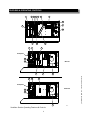
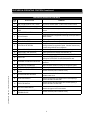
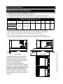
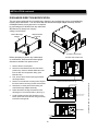
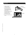
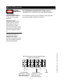
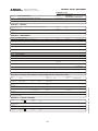
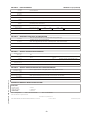
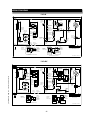
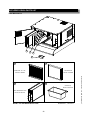
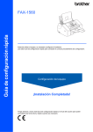
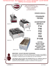
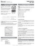
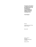
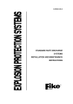
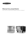
VENTLESS UNIVERSAL
HOOD SYSTEM
for ELECTRIC OVENS,
PROOFERS & HOLDERS
LVC-46
LVC-46X
Installation and
Operation
Instructions
2M-W2029 Rev. - 8/27/14
IL2629a
LVC-46
SAFETY SYMBOL
These symbols are intended to alert the user to the presence of
important operating and maintenance instructions in the manual
accompanying the appliance.
FOR YOUR SAFTEY
DO NOT STORE OR USE GASOLINE OR OTHER FLAMMABLE VAPORS AND LIQUIDS IN
THE VICINTIY OF THIS OR ANY OTHER APPLIANCE.
POST IN PROMINENT LOCATION
INSTRUCTIONS TO BE FOLLOWED IN THE EVENT USER SMELLS GAS. THIS
INFORMATION SHALL BE OBTAINED BY CONSULTING YOUR LOCAL GAS SUPPLIER.
AS A MINIMUM, TURN OFF THE GAS AND CALL YOUR GAS COMPANY AND YOUR
AUTHORIZED SERVICE AGENT. EVACUATE ALL PERSONNEL FROM THE AREA.
WARNING
IMPROPER INSTALLATION, ADJUSTMENT, ALTERATION, SERVICE OR MAINTENANCE
CAN CAUSE PROPERTY DAMAGE, INJURY OR DEATH. READ THE INSTALLATION,
OPERATION & MAINTENANCE INSTRUCTIONS THOROUGHLY BEFORE INSTALLING OR
SERVICING THIS EQUIPMENT.
WARNING
RISK OF FIRE OR ELECTRIC SHOCK
DO NOT OPEN
WARNING, TO REDUCE THE RISK OF ELECTRICAL SHOCK, DO NOT REMOVE
CONTROL PANEL. NO USER-SERVICABLE PARTS INSIDE.
REPAIRS SHOULD BE DONE BY AUTHORIZED SERVICE PERSONNEL ONLY.
NOTICE
Using any part other than genuine Lang factory supplied parts relieves the manufacturer of all
liability.
Due to periodic changes in designs, methods, procedures, policies and regulations,
the specifications contained in this sheet are subject to change without notice. While
Lang exercises good faith efforts to provide information that is accurate, we are not
responsible for errors or omissions in information provided or conclusions reached as a
result of using the specifications. By using the information provided, the user assumes all risks
in connection with such use.
MAINTENANCE AND REPAIRS
Contact your local dealer for service or required maintenance. Please record the model number, serial
number, voltage and purchase & Installation Information in the area below and have it ready when you
call to ensure a faster service.
Model No.:
Purchased From:
Serial No.:
Location:
Voltage:
Purchase Date:
1-Phase or 3 Phase:
Installed Date:
xi2
p/n 2M-W2029 OpM LVC- Ventless Universal Hood
Lang reserves the right to change specifications and product design without notice. Such
revisions do not entitle the buyer to corresponding changes, improvements, additions or
replacements for previously purchased equipment.
PROBLEMS, QUESTIONS or CONCERNS
Before you proceed consult you authorized Lang service agent directory
or
Call the Lang Technical Service & Parts Department at (314) 678-6315.
p/n 2M-W2029 OpM LVC- Ventless Universal Hood
TABLE OF CONTENTS
ELECTRICAL SPECIFICATIONS
1
FEATURES & OPERATING CONTROLS
2-3
PRECAUTIONS & GENERAL INFORMATION
4
AGENCY LISTING INFORMATION
5
INSTALLATION5
Unpacking & Inspection
5
Components
5
Under-Hood Appliance Limitations
6
Service Technician Installation Notes
7
Site Preparation
9
Mechanical Installation
9
Discharge Direction Modification
10-11
Electrical Installation
12-14
ANSUL® INSTALLATION & SETUP
13-14
Filter Installation
15
OPERATION16
Operation Lights
16
CLEANING INSTRUCTIONS
17-18
REQUIRED MAINTENANCE & MAINTENANCE LOGS 20-23
TROUBLESHOOTING SUGGESTIONS
24
WIRING DIAGRAM
25
EXPLODED VIEW & PARTS LIST
26-29
INTRODUCTION
Thank You for purchasing this Lang Manufacturing appliance.
Proper installation, professional operation and consistent maintenance of this appliance will ensure
that it gives you the very best performance and a long, economical service life.
This manual contains information and instructions for the ventless ventilation hood, its use and care.
For information regarding cooking appliance(s), please refer to the manufacturer’s operation manual.
ELECTRICAL SPECIFICATIONS
Model
LVC46
LVC46X
Volts
Amps
Power Supply
208/240V
4.3
For supply connection use #12 AWG copper wire only.
1
FEATURES & OPERATING CONTROLS
7
17
8
7 17
17
1
18
19
8
20
3
15
12
11
14
5
Nameplate
13
16
WVC-46
15
14
4
2
21
Nameplate
WVC-46X
13
16
2
Ventilator Section Operating Features & Controls
2
IL2631c
p/n 2M-W2029 OpM LVC- Ventless Universal Hood
6
FEATURES & OPERATING CONTROLS continued
FEATURES & OPERATION CONTROLS
p/n 2M-W2029 OpM LVC- Ventless Universal Hood
ITEM
NO
DESCRIPTION
COMMENT
1
VENTILATOR EXHAUST DUCT, FRONT
Exit point for ventilator airflow - on front of unit. DO NOT BLOCK
2
VENTILATOR FAN
Provides air movement for ventilation
3
HI-EFFICIENCY/CHARCOAL FILTER
PACK
Removes grease and smoke particles. Also assists in cooking odor
removal.
4
FIRE SUPPRESSION TANK
Container for ANSUL® Low-pH Liquid fire suppression fluid.
5
ACTUATOR ASSY
Triggers deployment of suppression fluid through manual pull station or
electric detection.
6
ANSUL® CARTRIDGE
Propels suppression liquid through suppression manifold and nozzles.
7
DISCHARGE NOZZLES
Fire suppression media discharges here, (3 places)
8
ELECTRICAL DETECTORS
Designed to activate at certain temperature. Activates (i.e. fire on the
cooktop) activates fire suppression system. Should be checked every
6 months during ANSUL® Service Inspection
9
APPLIANCE LIGHT (Not Shown)
ON when hood power switch is ON. Illuminates cooking area.
10
GREASE DRIP TRAY (Not Shown)
Collects grease/moisture dripping from baffle filter (16)
11
BAFFLE FILTER
Extracts and drains most greases and moisture from the air flow.
12
PRE-FILTER
Replaceable PRE-FILTER, stops large particles of grease from
reaching the FILTER PACK for reduced maintenance costs.
13
EQUIPMENT INTERFACE CONTACTOR
Energizes cooking appliances only while ventilator section is sensed as
operational.
14
BUILDING FIRE ALARM RELAY
Reports fire alarm condition to building fire management system.
15
DETECTION END OF LINE RELAY
Prevents appliance operation if a fault is found in detection circuit.
16
SUPPLY CONNECTION TERMINAL
BLOCK
Provides connection point for electrical circuitry
17
FILTER INTERLOCK SWITCHES
Proper installation of baffle filter and filter pack closes these switches in
ventilator sensor circuit
18
HEPA FILTER SWITCH
Montitors the HEPA filter and indicates when it needs replacing, if
ignored it will lead to unit shut down.
19
PRE-FILTER SWITCH
Monititors the Pre-Filter and indicates when it needs replacing, if
ignored it will lead to unit shut down.
20
UNIT SHUT-DOWN SWITCH
Shuts down the unit and appliances when the lack of air flow reaches a
certain level, triggers a service unit indicator.
21
FIRE PROTECTION CONNECTION
TERMIMAL BLOCK
Provides connection point for electrical circuitry
3
PRECAUTIONS AND GENERAL INFORMATION
This ventilator hood is part of an engineered system and is intended for
use in commercial establishments only.
SUFFOCATION HAZARD
Do not attempt to use this
ventilator with gas-fired units.
This ventilator will not remove
products of combustion.
Unvented exhaust gasses
can be deadly.
WARNING:
SHOCK HAZARD
All servicing requiring
access to non-insulated
electrical components must
be performed by a factory
authorized technician.
DO NOT open any access
panel which requires the use
of tools. Failure to follow this
warning can result in severe
electrical shock.
IMPORTANT:
The ventilator is disabled
when the filters are clogged
to the point of insufficient
airflow for proper operation. Also, power to the cooking
appliances is interrupted if
any filters or service panel
are removed.
It is the responsibility of
the store management to
maintain sufficient spares of filter packs to avoid
prolonged shutdown due
to a dirty or clogged filter
pack. Filter packs cannot be
cleaned.
Lang Manufacturing
assumes no liability for loss
of business due to a filter
related shutdown. Spare
filters can be purchased from
any authorized Lang servicer
or calling (314) 678-6315.
This ventilator is intended for commercial establishments for use
in the preparation food for human consumption. No other use is
recommended or authorized by the manufacturer or its agents.
Operators of this appliance must be familiar with the appliance use,
limitations and associated restrictions. Operating instructions must be
read and understood by all persons using or installing this appliance.
This ventilator hood system is designed to reduce odor emissions,
but will not completely eliminate all cooking odors. Air exchange
rates at the installation site must comply with the requirements of the
local jurisdictional authority. To ensure that odors do not accumulate,
recommended minimum air exchange is 200 cfm per linear foot of hood
into and out of the site.
This unit is intended for use with light- and medium duty electric
cooking appliances only. Cooking appliances placed under this
ventilator must comply with the restrictions set forth in the Installation
section of this manual.
Do not connect or energize this appliance until all installation
instructions are read and understood. Property damage or bodily
injury may result if these instructions are not followed. Disconnect this
appliance from electrical power before performing any maintenance or
servicing.
Cleanliness of this appliance is essential to good sanitation. Read and
follow all included cleaning instructions and schedules to ensure the
safety of the food product.
This appliance is not jet steam approved. Do not direct water jet or
steam jet at this appliance, or at any control panel or wiring.
Do not splash or pour water on, in or over any controls, control panel or
wiring. Do not attempt to wash filter packs. Water will cause their
immediate failure and disable the ventilator.
Exposed surfaces of this appliance can be hot to the touch and may
cause burns.
Avoid storing flammable or combustible materials in, on or near the ventilator or associated cooking appliance.
The technical content of this manual, including any wiring diagrams,
schematics, parts breakdown illustrations and/or adjustment
procedures, is intended for use by qualified technical personnel.
Any procedure which requires the use of tools must be performed by a
qualified technician.
All supplied instructions, diagrams, schematics, parts breakdown
illustrations, notices and labels must remain with the appliance if the
unit is sold or moved to another location.
This appliance is made in the USA. Unless otherwise noted, this
appliance has American sizes on all hardware.
4
p/n 2M-W2029 OpM LVC- Ventless Universal Hood
DANGER:
AGENCY LISTING INFORMATION
This appliance conforms to NSF Standard 4 for sanitation only if
installed in accordance with the supplied Installation Instructions
and operated and maintained in accordance with the instructions in this
manual.
US
3169406
This appliance is ETL listed.
UL710B
Recurculating System
INSTALLATION
UNPACKING & INSPECTION
Carefully remove the appliance from the carton. Remove all
protective plastic film, packing materials and accessories from the
appliance before connecting electrical power or otherwise performing
any installation procedure.
Carefully read all instructions in this manual and any other docments
packed with the appliance before starting any installation.
All documentation should remain with the equipment operator for future
reference.
Read and understand all labels and diagrams attached to the
ventilator.
Carefully account for all components and accessories before
discarding packing materials.
p/n 2M-W2029 OpM LVC- Ventless Universal Hood
COMPONENTS
Pre-Filter
Baffle Filter
Filter pack
Grease cup
1 ea.
1 ea.
1 ea.
1 ea.
Discharge Adapter Kit
1 ea.
Ansul® components - must be installed by an authorized Ansul® distributor only:
1 ea.
1 ea.
1 ea.
Fire suppression agent tank
Fire suppression agent (Ansulex® Low pH) 1.5 gal.
Fire suppression system charging cartridge
Store these components in a convenient place for later use.
NOTE: DO NOT discard
the carton or other packing
materials until you have
inspected the appliance for
hidden damage and tested it
for proper operation.
Refer to SHIPPING DAMAGE
CLAIM PROCEDURE on the
inside front cover of this
manual.
WARNING:
RISK OF INJURY
Installation procedures must
be performed by a qualified
technician with full knowledge
of all applicable electrical
codes. Failure can result in
personal injury and property
damage.
IMPORTANT:
Fire suppression system must
be charged and certified by an
authorized Ansul® distributor.
Ventilator will not operate and
cooking appliance will not be
energized until the Ansul® fire
suppression system has been
charged.
IMPORTANT:
After cooking appliances
are positioned under the
hood, swivel nozzles must
be positioned per Ansul®
recommendations.
5
INSTALLATION (continued)
UNDER-HOOD APPLIANCE LIMITATIONS:
1.
2.
3.
4.
Appliance must be installed per manufactures instructions.
Electrical appliances only. Not Intended for gas fired units.
All appliances under the hood must be connected to the hood appliance interlock circuit.
All appliances must meet the requirements outlined in the cooking appliance limitations chart below.
EQUIPMENT PARAMERTUER - LVC-46 (X)
Parameters Appliance
Type
Max Cooking
Temp
Max Single Units
Cooking Area
Dim “A” (1)
Min.
Dim “A” (2)
Min.
550°F (287°C)
19 Cubic Feet
1”
6”
Dim “B” (3) Dim “C” (4) Dim “D” (5)
Min.
Min.
Min.
Convection Oven
Double Stack Oven
Steamer/Combi Oven
3”
0”
8”
Bakery Oven / Proofer
1. Dim “A” minimum distance from the lower edge of the hood skirt and the top of the appliance.
2. Dim “A” maximum distance from the lower edge of the hood skirt and the top of the appliance.
3. Dim “B” minimum overhang between the hood side skirt and the appliance side.
4. Dim “C” minimum space between the hood rear skirt and the back panel of the appliance.
5. Dim “D” minimum overhang between the front lower edge of the hood to the oven’s heated surface.
45.82”
FRONT VIEW
A
D
52.20”
C
p/n 2M-W2029 OpM LVC- Ventless Universal Hood
B
SIDE VIEW
Intended for installation in accordance with:
The standard for ventilation control and fire
protection of commercial cooking operations
NFPA 96, the National Electric Code NFPA 70
and local codes where applicable.
Only electrically heated appliances are
acceptable for installation. Appliance Operation
Requires the Fire suppression system be setup,
charged and certified by an authorized ANSUL®
distributor. The airflow monitoring system
will prevent appliance operation if insufficient
airflow is detected or all filters are not in place. The service panel must be in place for blower
operation.
IL2871
6
INSTALLATION (continued)
SERVICE TECHNICIAN INSTALLATION NOTES
This ventilator hood is to be used with light-duty and medium-duty
electrically powered cooking appliances only.
••
DO NOT attempt to use this ventilator hood with gas-fired units.
••
DO NOT use this ventilator hood with electrical appliances whose
dimensions or wattage characteristics exceed those defined in the Under Hood Cooking Appliance Limitations, page 6.
Installation and start up must be performed by an Authorized
Installation Company.
Ansul® Installer must complete the WARRANTY INITIATION form
(2M-303912) included with the unit for the warranty to begin, and record
installation particulars on the CUSTOMER SERVICE DATA form
located at the end of this manual.
IT is the responsibility of the installer to verify that this VENTILATOR
installation is in compliance with the specifications listed in this
manual, with local code requirements, and in accordance with N.F.P.A
96 the STANDARD FOR VENTILATION CONTROL AND FIRE
PROTECTION OF COMMERCIAL COOKING OPERATIONS.
WARNING: IMPROPER INSTALLATION, ADJUSTMENT, ALTERATION,
SERVICE OR MAINTENANCE CAN CAUSE PROPERTY DAMAGE, INJURY
OR DEATH. READ THE INSTALLATION, OPERATION AND MAINTENANCE
INSTRUCTIONS THOROUGHLY BEFORE INSTALLING OR SERVICING
THIS EQUIPMENT.
p/n 2M-W2029 OpM LVC- Ventless Universal Hood
WARNING: THIS PRODUCT IS NOT PROVIDED WITH AN INTEGRAL
FIRE EXTINGUISHING SYSTEM. AUTHORITIES HAVING JURISDICTION
SHOULD BE CONSULTED AS TO THE REQUIREMENT FOR THIS
EQUIPMENT WITH RESPECT TO FIRE EXTINGUISHING SYSTEMS, SUCH
AS THE NEED FOR FIELD INSTALLED SYSTEMS IN ACCORDANCE WITH
NFPA 96.
DANGER:
SUFFOCATION HAZARD
Do not attempt to use this
ventilator with gas-fired units.
This ventilator will not remove
products of combustion.
Unvented exhaust gasses
can be deadly.
WARNING:
SHOCK HAZARD
All servicing requiring
access to non-insulated
electrical components must
be performed by a factory
authorized technician.
DO NOT open any access
panel which requires the use
of tools. Failure to follow this
warning can result in severe
electrical shock.
CAUTION:
RISK OF
DAMAGE
DO NOT connect or energize
this appliance until all
installation instructions are
read and followed. Property
damage or bodily injury could
result if these instructions are
not followed.
IMPORTANT:
If a remote pull station is to
be used, ventilator cannot be
moved without first disabling
the remote pull station.
Contact your Ansul® agent
for details.
7
INSTALLATION (continued)
Site Preparation
1. Provide clearance around installation site to safety rig and lift
equipment into its final position. Consider general service and
installation space when locating unit.
2. Thoroughly review the plans and specification of the project.
3. Determine the exact location in which the cooking hood will be
installed and verify that there are no interferences, which will
prevent proper installation.
4. Verify that all overhead beams and angles are structurally strong
enough to support the weight of the hood and hanging system.
It is often necessary to strengthen existing structural beams, as
they are not designed to carry the weight of a stainless steel hood.
Refer to the project submittal drawing for hood weight(s). It may
also be necessary to create a support structure suspended from
the ceiling joists to better align with the desired hood location.
p/n 2M-W2029 OpM LVC- Ventless Universal Hood
5. Determine if adequate room is available to install the hood with
proper clearance from combustible material. IMC, NFPA96 and
local authorities having jurisdiction call for a minimum clearance
(typically 18 inches) between the cooking hood(s) and building
materials, which are combustible. However, IMC and NFPA96
outline acceptable clearance reduction methods. It is important to
check with the local authority having jurisdiction to determine that
the installation method is satisfactory to meet their requirements
prior to installing the equipment.
8
INSTALLATION (continued)
MECHANICAL INSTALLATION
The following is a step-by-step procedure for installation of the Recirculating Hoods.
1. Uncrate the hood, being very careful not to dent or scratch the outer surface. NOTE Report any
damage to the delivering freight carrier and file a claim if appropriate. Refer to the installation
drawing for typical details of the ventilation system prior to hanging the hood. Check the nameplate
on the equipment to make certain it meets the specifications provided by the architect and or
engineer. If discrepancies exist, notify the manufacturer immediately.
2. It’s important that you have read and understand “Site Preparation” before continuing with the installation
of the hood. See Table on page 6 “EQUIPMENT PARAMERTUER”.
3. Determine the exact location of the hood. Ensure support beams are structural support system is
the responsibility of the contractor and the structural engineer.
4. Use 1/2-13 threaded rod to hang the hood. Drill 5/8” holes in the structural support system using
dimensions provided below.
5. Each corner of the hood has a pre-punched hole. It is important that the 1/2-13 threaded rod that
will be used to suspend the hood is secured at these locations. Each hole has a 14 gauge steel
support plate that is riveted to the inside of the lid to strengthen the hood corners. Do not remove or
relocate these plates.
6. Raise the hood into position using high lifts or equipment jacks at each end of the hood to ensure the
hood is level. When the hood is elevated to the proper height, install 1/2-13 threaded rod between
the hood support plates and the modified supports in the ceiling.
7. Make final adjustments as needed to ensure that the hood is level. Maintain tension on all the rods
to ensure hood weight is evenly distributed.
p/n 2M-W2029 OpM LVC- Ventless Universal Hood
42
35”
”
1/8
3 9/3
2”
3/8” Top
Mounting Hole
3 3/4
”
”
/16
5
11
15 3
3/8” Rear
Mounting Hole
FRO
NT
IL2636b
9
/16”
INSTALLATION continued
DISCHARGE DIRECTION MODIFICATION
The unit comes configured for a front discharge, changing it to a top discharge can be accomplished by
following these instructions. The unit comes with the Vertical Discharged Adapter Assembly & CloseOff Adapter Bracket, these parts can be re-aquiired
by purchasing pn N1-WL0645 from any authorized
Well Servicer or directly from Lang by
calling (314) 678-6315.
Vertical Discharge
Adapter
Adapter Bracket
Close-Off
IL2853
BLOWER ACCESS PANEL
Before attempting to perform any maintenance
or modifications: read instructions thoroughly & disconnect ventilator from power source.
BLOWER TUBE CONNECTION
1. Remove blower access panel
2. Disconnect clear flexible tube from the blower
pressure tap. Remove flexible distribution tube
from the tank and compression fitting. (See
illustration #2)
3. First, remove the 2 screws securing the blower
discharge bracket.
FLEXIBLE DISTRIBUTION HOSE
IL2869
BLOWER DISCHARGE
BRACKET SCREWS
5. Rest blower on deck panel while locating the
vertical discharge adapter assembly.
6. Rotate the blower 90 deg.Clockwise until the
discharge is in the vertical position. (See Fig. 4)
7. Locate vertical mounting hole locations on the
blower panel and secure blower using previously
removed mounting bolts.
BLOWER MOUNTING
BOLT LOCATIONS
FIG #3
VERTICAL MOUNTING
HOLE LOCATIONS
FIG #4
IL2851
10
p/n 2M-W2029 OpM LVC- Ventless Universal Hood
4. Remove 2 of the blower mounting bolts. Support
the blower before removing the 3rd and final bolt.
INSTALLATION
8. Install the vertical adapter at the
discharge of the blower.
SLIDE BRACKET OVER
BLOWER DISCHARGE,
SECURE WITH 8-32 SCREWS
9. Secure adapter bracket use (6)
8-32 screws. (Not provided)
STEP 10 - INSTALL FIRE DAMPER
INTO BLOWER ADAPTER
10. Remove the fire damper from the
horizontal discharge and install it
into the vertical discharge adapter
assembly. See Fig 5
11. Reconnect discharge flex tubing and
blower pressure switch tube. Verify that
tubing is secure and tight.
FIG #5
STEP 12 - SECURE ADAPTER BRACKET
CLOSE-OFF WITH 8/32 SCREWS (7)
12. Install adapter bracket close-off
part # NI-Z18760. See Fig 5
INSERT FIRE DAMPER
INTO THE VERTICAL
ADAPTER ASSEMBLY
13. Replace blower access panel
14. Reconnect power supply and verify unit
operation.
p/n 2M-W2029 OpM LVC- Ventless Universal Hood
IL2852
11
INSTALLATION
ELECTRICAL INSTALLATION
Refer to the nameplate on the ventilator. Verify ELECTRICAL
SERVICE POWER. Voltage and phase must match the nameplate
specifications, and available electrical service amperage must meet or
exceed the listed amperage. Refer to specifications listed on page 1 of
this manual.
DANGER:
SUFFOCATION HAZARD
Do not attempt to use this
ventilator with gas-fired units.
This ventilator will not remove
products of combustion.
Unvented exhaust gasses
can be deadly.
The ground lug of this ventilator must be connected to a suitable
building ground.
Open the front control panel to access the cooking appliance contactor
and builign alarm relay. Wire the cooking appliance control circuit to
the terminal block per the figure below. NOTE: It is the responsibility of the electrical contractor to provide
suitable wiring, flexible or rigid conduit, and an appropriate strain relief.
WARNING
SHOCK HAZARD
Electrical Connection
Electrical connections must
be made by a licensed
electrician.
NOTE: The hood requres a single phase (1ph), 208 or 240 volt, 20
amp suppy. When connecting line voltage to the unit’s terminal block,
use a minimum of #12 gage copper wire only, suitable for 167°F (76°C)
ambient temperature.
CAUTION:
Appliance Connections
FIRE HAZARD
HEALTH HAZARD
All under hood appliances are required to be interlocked with the hood’s
equipment cut-off circuit, through a customer supplied contactor. This
contactor must be a UL listed, definite purpose AC resistive air heating type,
suitable for the appliance load. Installation and connections shall be in
accordance with the National Electric Code NFPA 70. These connections
provide an automatic shutdown of the appliance when the hood is OFF, or in
the event of a malfunction or appliance fire.
All cooking appliance must
be connected to the cooking
appliance contactor, the
control circuit of which is
controlled by the ventilator.
Failure to control cooking
appliances will provide no
protection in the event of a
fire, nor will cooking vapors
and odors be contained in
the event of ventilator hood
Equipment Cutoff Connections
Opt 1: Use TB#3 & TB#4 for 208 or 240 volt control circuit. These contacts will be
de-energized when the hood is OFF or in the event of a malfunction
LINE INPUT
208-240VAC
50/60HZ
TO CUSTOMER
TO CUSTOMER
SUPPLIED APPLIANCE
SUPPLIED
CONTACTOR
SWITCHING
(240V CNTR CIRCUIT) DEVICE (SPST)
OPTION 1
TO APPLIANCE
TB3
TB4
OVER CURRENT
PROTECTED
SUPPLY
BUILDING
ALARM
INTERFACE
OPTION 2
TO APPLIANCE
CUSTOMER
SUPPLIED
CONTACTOR(S)
TB8
TB7
TB6
TB5
L2
TB4
TB2
L1
TB3
TB1
control circuits with voltages other than 208 or 240 AC. These contacts will be
open when hood is OFF or in the event of a malfunction.
208/240V
APPLIANCE CUSTOMER
SUPPLIED
CONTROL
EQUIPMENT CONTACTOR(S)
CUTOFF
TERMINALS
EQUIPMENT INTERFACE OPTION 1
TB5
T3
TB6
L3
OVER CURRENT
PROTECTED
SUPPLY
CUSTOMER
SUPPLIED
SOURCE CIRCUIT
EQUIPMENT INTERFACE OPTION 2
12
SPST
SWITCHED
EQUIPMENT
CUTOFF
TERMINALS
IL2376a
p/n 2M-W2029 OpM LVC- Ventless Universal Hood
Opt 2: Use TB#5 & TB#6 as a Normally Closed SPST relay connection for equipment
INSTALLATION continued
The alarm relay is activated by the Ansul® fire detection system. If the
installation includes a building alarm system, connect to terminals T7 &
T8 of the terminal block in supply connection box. These terminals are
configured from the factory for normally open operation.
The ventilator will operate properly, and the appliance control relay will
be energized, only when:
1. The VENTILATOR POWER SWITCH is “ON”.
2. The Ansul® Fire Suppression System is charged and armed.
3. All filters are in position and serviceable, and the ventilator air flow
system is satisfied.
FIRE SUPPRESSION SYSTEM INSTALLATION
THE FIRE SUPPRESSION SYSTEM is comprised of one container
of Ansulex® Low pH liquid fire suppression media and a system
pressurization canister, plus associated plumbing. Actuation controls are
contained in the Automan enclosure.
The hood is not supplied with a field installed MANUAL PULL STATION,
which must be set-up at the time of installation by an authorized Ansul®
distributor.
The MANUAL PULL STATION allows for for manual emergency
shutdown of cooking appliance power, and actuation of the fire
suppression system.
Three (3) NOZZLES disperse the fire suppression media. These nozzles
protect the fan and plenum.
p/n 2M-W2029 OpM LVC- Ventless Universal Hood
If the ventilator is situated such that the supplied manual pull
station cannot be installed or is not readily accessible, a REMOTE
MANUAL PULL STATION may be required by local codes. Any
such remote manual pull station must be installed by an authorized
Ansul® distributor in accordance with the AUTHORITY HAVING
JURISDICTION.
The fire detection system utilizes one electronic thermal detector with an
actuation set point of 275°F (135°C).
The signaling from the detection devices will automatically discharge
the fire suppression media through all nozzles, disable the cooking
appliances and cause the alarm to sound.
Fire supression media will form an emulsion designed to both smother
and cool the fuels in/on the cooking appliance.
DANGER
FIRE HAZARD
Fire suppression system
must be charged and certified
by an authorized Ansul®
distributor.
DO NOT attempt to modify or
bypass the fire suppression
system.
An uncontrolled fire can
cause serious injury or death.
NOTE:
If the fire suppression system
is discharged, a buzzer will
sound continuously. The unit
will remain inoperable until
the fire suppression system is
serviced, recharged and reset
by an authorized Ansul®
distributor.
Charging of the Ansul®
Fire Suppression system
must be in accordance with
Ansul® Design, Installation,
Recharge and Maintenance
Manual, #418087.
NOTE:
If a REMOTE MANUAL PULL
STATION is installed, moving
the ventilator for any reason
may cause the Ansul®
system to discharge.
IMPORTANT:
Should the fire suppression
system discharge: all nozzles
must be replaced, and all
lines thoroughly cleaned,
prior to recharging the
system.
Residual fire suppression
media may compromise the
flow and dispersion of fire
suppression media in any
subsequent activation.
13
INSTALLATION continued
DANGER
BURN HAZARD
Any additional remote pull
station must NOT be installed
on the front of the cooking
appliances,
FIRE SUPPRESSION SYSTEM INSTALLATION (continued)
The MANUAL PULL STATION and any similar REMOTE MANUAL
PULL STATION will activate the fire suppression system when the
ring on the pull station is pulled to its full extent.
Discharge of the fire
extinguishing system into hot
grease or oil may cause hot
foam to spill over from the
cooking surface or frypot.
Serious burns and other injuries
can result from contact with hot
oil and from slipping in spilled
oil.
N.C.
TO CUSTOMER
SUPPLIED U.L. LISTED
RELEASING CONTROL
UNIT (120V RATED)
COM
N.O.
TO CUSTOMER
SUPPLIED U.L. LISTED
ANSUL ELECTRIC
SWITCHING DEVICE
14
TB14
TB13
TB12
TB11
TB10
TB9
DETECTION AND ACTIVATION CONNECTIONS
MODEL WVC-46X (ONLY)
OPEN
IL2854
p/n 2M-W2029 OpM LVC- Ventless Universal Hood
The manual pull station is
installed on the right side
(facing the unit. It may,
however, be relocated to the left
side of the ventilator hood by an
authorized Ansul® agent.
INSTALLATION
FILTER INSTALLATION
Note air flow direction arrow on filter pack. Remove old filter pack and slide new filter pack fully into the appropriate slot. Verify that the airflow arrow points toward the fan.
23.3”
HEPA FILTER
PRE-FILTER
BAFFLE
FILTER
NOTE:
The BAFFLE FILTERS,
PRE-FILTERS and FILTER
PACK actuate position
switches when they are
properly positioned. They
must be properly installed
for the under hood cooking
appliance contactor to be
energized.
30”
Air
t
us
ha
Ex
WARNING
SLIP AND FALL
HAZARD
GREASE
CUP
IL2637a
The bafffle filter is reusable and should be cleaned at least weekly. Change the pre-filter and Hepa filter pack as indicated on the front
panel. These filters are disposable and cannot be reusable. All filters
are accessible throught the front service door.
p/n 2M-W2029 OpM LVC- Ventless Universal Hood
Use only genuine Lang replacement parts and filters,
call (314) 678-6315 or your authorized Lang service agent. Parts
supplied by others will void your warranty and may not provide safe
operation.
BAFFLE FILTER and GREASE CUP INSTALLATION
1. Install baffle filter from front. Engage the baffle filter in the retainer slot. Push up until the baffle filter bottom clears the lower lip of the retainer, then lower the baffle filter into the bottom retainer
2. Install GREASE CUP into brackets below the baffle filter.
Note: Failure to install the GREASE CUP will allow grease and
moisture from the BAFFLE FILTER to drop into hot cooking surfaces,
creating both a SAFETY HAZARD (hot oil splatter).
15
DO NOT operate any
grease-producing cooking
appliance unless the grease
cup is properly installed. Oil
will drip onto floor creating a
slipping hazard.
CAUTION
BURN HAZARD
DO NOT operate any cooking
appliance unless the grease
cup is installed.
Moisture dripping onto hot
surfaces, oil or grease can
cause splattering.
OPERATION
HOT SURFACE
Exposed surfaces can be hot
to the touch and may cause
burns.
Control Panel
NOTE: Cooking appliances must
be operated in accordance with the
manufacturer’s instructions.
CAUTION:
During normal operation, the illuminated
power switch will be the only light on the
control panel that will be ON.
DO NOT splash or pour water
or grease onto control panel
or wiring.
If the CHECK FILTERS light illuminates,
check BAFFLE FILTERS, PREFILTERS,
and the HEPA AIR FILTERS for proper
installation.
SHOCK HAZARD
IMPORTANT:
The ventilator cannot operate
if the filter pack is removed or
clogged.
It is the responsibility of
the store management to
maintain sufficient spares
of filter packs to avoid prolonged shutdown of the
ventilator when this filter is
expended.
Filter packs cannot be
cleaned.
Lang Manufacturing assumes
no liability for loss of business
due to filter related shutdown.
Filters that are not genuine
Lang Replacement Parts may
cause your unit to operate
incorrectly and you will risk
the possibility of voiding your
warranty.
SERVICE
REQUIRED
If the REPLACE PRE-FILTERS light
illuminates .. Replace the Pre-filters.
REPLACE
FILTER PACK
If the REPLACE FILTER light
illuminates, replace the FILTER PACK.
NOTE: the REPLACE FILTERS light is
a warning that filter pack is nearing the
end of its service life. The ventilator will
continue to operate for a period of time
after the REPLACE FILTER LIGHT turns
ON to allow continued operation through
a peak period. However, filter pack must
be replaced within a short time period or
it will clog, disabling the ventilator and
appliances.
REPLACE
PREFILTER
ON
CHECK
FILTER
POWER
If the SERVICE REQUIRED light
OFF
illuminates, the filter pack is restricted to
the point of insufficient airflow for proper
IL2870
operation and the Ventilator will shut
down until the underlying clogged filter situation has been corrected. Replace clogged item with a fresh filter to correct the condition. Reset the unit by turning VENTILATOR POWER SWITCH to OFF,
then back to ON.
A failure of incoming electric power will cause a shut down of the unit.
Reset the unit by turning VENTILATOR POWER SWITCH to OFF, then
back to ON.
Operation Lights
There are two equipment lights that provide illumination of the working
area. These lights are controllled by the main power switch.
16
p/n 2M-W2029 OpM LVC- Ventless Universal Hood
CAUTION:
CLEANING INSTRUCTIONS
PRECAUTIONS: Disconnect unit from electric power and allow to cool
Cover frypot to prevent oil contamination
FREQUENCY:
Weekly
TOOLS:
Mild detergent, clean non-abrasive towels
NOTE: Ventilator section to be cleaned in conjunction with cooking
appliance. Refer to appliance user instructions for cleaning procedure.
CAUTION:
HOT SURFACE
Exposed surfaces can be hot
to the touch and may cause
burns. Allow unit to cool
before cleaning.
CAUTION:
SHOCK HAZARD
1. TURN HOOD POWER SWITCH TO OFF.
Cover cooking appliance to prevent oil contamination.
2. Remove BAFFLE FILTERS and GREASE CUP(s).
3. Empty GREASE CUP(s) into an appropriate grease collection
receptacle.
4. Clean BAFFLE FILTERS and GREASE CUP(s) in a sink or dishwasher
using mild detergent and warm water.
5. Dry components with a clean non-abrasive cloth.
Reinstall BAFFLE FILTERS and GREASE CUP(s) in ventilator.
6. Wipe exterior of ventilator with a clean cloth moistened with warm water and mild detergent. Rinse by wiping with a clean cloth moistened with warm water.
7. Uncover the cooking appliance and reconnect unit to electric power.
p/n 2M-W2029 OpM LVC- Ventless Universal Hood
Procedure is complete
17
DO NOT splash or pour water
or grease onto control panel
or wiring.
CLEANING INSTRUCTIONS
CAUTION:
HOT SURFACE
Exposed surfaces can be hot
to the touch and may cause
burns. Allow unit to cool
before cleaning.
CAUTION:
PRECAUTIONS: Disconnect unit from electric power and allow to cool
Cover cooking surfaces and frypots to prevent
contamination.
FREQUENCY:
Monthly
TOOLS:
Mild detergent, clean non-abrasive towels
NOTE: Ventilator section to be cleaned in conjunction with cooking
appliance. Refer to appliance user instructions for cleaning procedure.
SHOCK HAZARD
DO NOT splash or pour water
or grease onto control panel
or wiring.
IMPORTANT:
DO NOT wash FILTER
PACK. Washing these filters
will clog them, and cause
installed cooking appliance
to be disabled.
IMPORTANT:
DO NOT clean interior of
ventilator by spraying.
1. TURN HOOD POWER SWITCH TO OFF.
Cover cooking applaince to prevent oil contamination.
2. Remove BAFFLE FILTERS, GREASE CUP(s), and all FILTER PACK(s).
3. Wipe interior of ventilator with a clean cloth moistened with warm water
and mild detergent. Rinse by wiping with a clean cloth moistened with
warm water. DO NOT clean by spraying.
4. Dry ventilator thoroughly with a clean non-abrasive cloth.
Reinstall all FILTERS, BAFFLE FILTERS, GREASE CUP(s).
5. Uncover the cooking appliance and reconnect unit to electric power.
Procedure is complete
Spraying can contaminate the
cooking appliance, and may
cause internal damage to the
ventilator blower, operation
proofing system and/or fire suppression system.
p/n 2M-W2029 OpM LVC- Ventless Universal Hood
Clean by wiping only.
18
REQUIRED MAINTENANCE
USE AND MAINTENANCE SHALL BE IN ACCORDANCE WITH THE
STANDARD FOR VENTILATION CONTROL AND FIRE PROTECTION
OF COMMERIAL COOKING OPERATIONS, N.F.P.A. 96 (current
edition).
3-MONTH MAINTENANCE:
Thoroughly clean entire HOOD PLENUM and BLOWER section.
IMPORTANT:
Per NFPS 96, a signed and
dated VENTILATOR HOOD
MAINTENANCE LOG
must be maintained on the
premises, and be made
available for inspection by the
authority having jurisdiction
upon request.
6-MONTH MAINTENANCE:
Inspection and testing of total operation including FIRE DAMPER and
all SAFETY INTERLOCKS shall be performed by qualified service personnel.
All FIRE SUPPRESION SYSTEM actuation components including
MANUAL PULL STATION and any REMOTE MANUAL PULL STATION
must be inspected for proper operation in accordance with the
maintenance schedule published in ANSUL® R-102 SYSTEM DESIGN,
INSTALLATION, RECHARGE AND MAINTENANCE MANUAL (418087).
ANNUAL (12-MONTH) MAINTENANCE:
NOZZLES and MANUAL PULL STATION must be cleaned in
accordance with ANSUL® R-102 SYSYTEM DESIGN, INSTALLATION,
RECHARGE AND MAINTENANCE MANUAL (418087).
12-YEAR MAINTENANCE:
p/n 2M-W2029 OpM LVC- Ventless Universal Hood
The FIRE SUPRESSION AGENT TANK must be HYDROSTATICALLY
TESTED, and the FIRE EXTINGUISHING AGENT must be REPLACED
in accordance with the maintenance schedule published in ANSUL®
R-102 SYSTEM (STANDARD UL 300 LISTED). This maintenance to be
performed by qualified Ansul® service personnel only.
19
IMPORTANT:
Should the fire suppression
system discharge, all
lines and nozzles must be
thoroughly cleaned prior to
recharging the system.
Be sure to note such cleaning
on the hood maintenance log.
Residual fire suppression
media may compromise the
flow and dispersion of fire
suppression media in any
subsequent activation.
20
p/n 2M-W2029 OpM LVC- Universal Hood
OPERATION
Lang Manufacturing
AGENT / DATE
IL2873
VENTILATOR HOOD OWNERS MONTHLY INSPECTION LOG
21
Max interval: 12 months
Replace fire damper fusible link:
rated @ 212ºF
Inspect fire suppression detectors, all releasing devices for
actuation, fire suppressant tank liquid level
Max interval: 6 months
(discharge of fire suppressant not a part of this test)
OPERATION
p/n 2M-W2029 OpM LVC- Universal Hood
AGENT / DATE
IL2874
VENTILATOR HOOD MAINTENANCE LOG
Lang Manufacturing
ANSUL®
MATERIAL SAFETY DATA SHEET
A N S U L IN C O R P O R AT E D
M A R IN E T T E , W I 5 4 14 3-2 54 2
ANSULEX Low pH
Q U IC K ID E N TIFIE R (In P la n t C o m m o n N a m e )
M a n u fac tu re r’s
Nam e:
ANSUL INCORPORATED
E m erg e nc y
Tele p h o n e N o .:
CHEMTREC
(800) 424-9300 or (703) 527-3887
A d d re ss :
O ne Stan to n Stre e t, M a rin ette, W I 54 1 43 -25 42
O th e r In fo rm a tio n
C a lls :
(7 15 ) 7 35 -74 11
P re pa re d B y :
S a fe ty an d H ea lth D e pa rtm en t
D a te Pre pa re d :
F e brua ry 1, 19 99
SECTION 1 - IDENTITY
C o m m o n N a m e (U s e d o n La b e l):
(Tra d e N a m e a n d S yn o n ym s )
C h e m ic a l
Nam e:
Fo rm u la :
C A S N o .:
A N S U LE X L ow p H L iq uid F ire S up pre ss a nt
N /A T his is a M ix tu re
N /A
C h e m ic a l
Fa m ily :
M ix tu re
CAS No.
A C G IH TLV
A cu te To xicity D a ta
N /A
N /A
N /A
SECTION 2 - INGREDIENTS
PART A - HAZARDOUS INGREDIENTS
P rinc ipa l H az a rd o u s C o m p o n e n t(s ) (c h em ica l a n d c o m m on n a m e (s )):
W t.%
N o ne
N /A
N /A
PART B - OTHER INGREDIENTS
W t.%
CAS No.
A C G IH TLV
A cu te To xicity D a ta
P ro prie ta ry M ix tu re o f O rga nic an d Ino rg an ic S a lts
4 8.0 - 50 .0
N /A
N /E
NDA
P h os p ho ric A cid
0 .2
7 66 4-3 8-2
N /E
NDA
E D TA
0 .65
6 4--0 2-8
N /E
NDA
Ye llow -G re en F lu ore sc e nt D ye
0 .011
5 18 -47 -8
N /E
O ra l L D 50 (rat)
6 80 0 m g /k g
W a te r
A p pro x . 5 0.0
7 73 2-1 8-5
N /E
NDA
O th e r C om p o n e n t(s ) (c h e m ica l a n d co m m o n n a m e (s )):
SECTION 3 - PHYSICAL AND CHEMICAL CHARACTERISTICS (Fire and Explosion Data)
11 3ºC
P e rce n t Vo la tile
b y Vo lu m e (% ):
A p pro x . 5 0.0
S o lu b ility
in W a te r:
1 00 %
A p p ea ra nc e
a n d O d o r:
F luo re sc en t Ye llo w C o lo re d L iq uid, M ild O d or
Fla sh P o in t:
N o ne to b oilin g
Sp e c ia l Fire
Fig h tin g P ro ce d u re s :
N O N E - T H IS IS A N E X T IN G U IS H IN G A G E N T
U n u su a l Fire a n d
E xp lo sio n H a z a rd s :
Va p o r D e n sity:
(A ir = 1 ):
1 .03
Fla m m a b le L im its
in A ir % b y Vo lu m e :
N /A
Sp e c ific
G ra vity (H 2 O = 1):
1 .33
E va p o ra tio n R a te :
(B u tyl Ac e ta te = 1):
A p pro x . 0 .0 05
R e a ctivity in
W a ter:
M ild e x oth e rm ic rea c tio n
E xtin g uish e r
M e d ia :
N /A
Va p o r P re ss u re
(m m H g ):
A u to-Ig n itio n
Tem p e ra tu re :
N o ne
SECTION 4 - PHYSICAL HAZARDS
U n sta b le
Sta b le
Sta b ility:
In co m p a tib ility
(M a te ria ls to Av o id ):
N /A
R e ac tive M eta ls , C lF 3 , e lec tric ally en e rgize d eq uipm e nt, an y m aterial rea c tiv e w ith w ate r.
H a za rd o us
D e co m p o s itio n P ro d u c ts :
H a za rd o us
P o ly m e riz a tio n :
C o n d itio n s
to A vo id :
M a y O cc u r
W ill N o t O cc ur
N o t e sta blis he d, ac rid fum e s.
C o n d itio n s
to A vo id :
N /A
29 22
N o t D e te rm ine d
N /A
p/n 2M-W2029 OpM LVC- Universal Hood
B o ilin g
P o in t:
SECTION 5 - HEALTH HAZARDS
Th res h o ld
L im it Va lu e :
ANSULEX Low pH (continued)
N o ne E s tab lish ed
R o u te s o f E n try:
E ye C o n tac t:
Irritan t
S kin C o n ta c t:
Irritan t
In h a la tio n:
N o t a n ex pe c ted ro ute o f en try. C a n b e irritating to m u co us m e m bra ne s .
In g e stio n :
Irritating to m u co us m e m bra ne s . A c u te O ral L D 50 (Sp rag u e-D a w le y rats ) 8 25 .5 m g/k g .
A c ute E xp o su re: M a terial irrita tes s k in , e ye s , a nd m uc o us m em b ran e s.
C h ron ic E x p os ure: N o ne k no w n.
S ig n s an d
S ym p to m s:
M e d ic a l C o n d itio n s G e n era lly
A g g ra va te d b y E xp o s u re :
N o ne k no w n.
C h e m ic a l L iste d a s
C a rc in o g e n o r P o te ntia l:
N a tio n a l To xico lo g y
P ro g ra m :
Ye s
No
Ye s
No
I.A .R .C
M o n o gra p h s:
Ye s
No
OSHA
SECTION 6 - EMERGENCY AND FIRST AID PROCEDURES
F lus h an d irriga te w ith w ate r for 15 m in ute s w h ile h olding e ye lids o pe n.
If irritation p ers ists , s ee k m ed ic al a tte ntio n.
E ye C o n tac t:
W a sh tho ro ug hly w ith s oa p an d w ater. If irritatio n p e rsists , s e ek m ed ic a l a tte ntio n.
S kin C o n ta c t:
F re s h air if sy m ptom s o cc ur. If irrita tio n pe rs is ts, se e k m e dica l atten tion .
In h a la tio n:
D ilute by d rin king larg e qu an titie s of w ater.
In g e stio n :
SECTION 7 - SPECIAL PROTECTION INFORMATION
R e sp ira to ry P ro te ctio n
(Sp e cify Typ e ):
N /A
Ve n tila tio n:
L o ca l
E xh a u st:
P ro te ctive
G lo ve s :
M e ch a n ica l
(G e n e ra l):
N /A
E ye
P ro te ctio n :
R u bb er glov es for sp ill/lea k
O th e r Prote c tiv e
C lo th in g o r E q uip m e n t:
N /A
C h em ic a l g og gles re c om m en de d du rin g
s pill/le ak p roc e du res .
E y e w as h an d sa fe ty s ho w ers are g oo d s a fety pra c tic e.
P re ca u tio n s to b e ta k e n
in H a n d lin g a n d Sto ra g e :
Store in origina l c o nta in er. K e ep tig htly clos e d. K e ep s epa ra te fro m ac id .
O th e r
P re ca u tio n s:
S e e in co m patibility in fo rm ation in S ec tion 4.
Stop lea ks . C o ntain sp ills . R em o ve a s m u c h a s po s sible. P lac e in c lo se d co nta in er fo r prop er disp os a l
W a sh s p ill a rea w ith la rge a m o un ts of w ater to rem o ve trac es a nd n eu tra lize .
Ste p s to b e tak e n in C a s e
M a te ria l is R e le a s e d or Sp ille d :
p/n 2M-W2029 OpM LVC- Universal Hood
W a ste D isp o sa l
M e th o ds :
D is p os e of in c om p lia n ce w ith lo ca l, sta te an d fe de ral re gu la tio n s.
HAZARDOUS MATERIAL IDENTIFICATION SYSTEM
HAZARD INDEX
4
3
2
1
0
SE V E R E H A ZA R D
SE R IO U S H A ZA R D
M O D E R ATE H AZ AR D
SL IG H T H AZ AR D
M IN IM A L H A ZA R D
N /A = N o t A pp lica b le
0 H E A LTH
0 FL A M M AB IL ITY
0 R E A C TIV ITY
N D A = N o D a ta Av a ila b le
N /E = N o t E sta blis he d
A N SU L a n d AN S U L E X a re re g is te re d tra d e m a rks .
In te rn e t A d d re s s: h ttp ://w w w.a n s u l.c o m
A N SU L IN C O R P O R ATE D , O N E S TA N TO N S TR E E T, M A R IN ET TE , W I 5 4 1 4 3 -2 5 4 2
Fo rm N o . F-9 0 1 6 0 -6
23
30
© 1 9 9 9 A n su l In co rp o ra te d
503 p/n 2M-304989 Owners Manual WVF-886 Ventless Fryer
SECTION 8 - SPECIAL PRECAUTIONS AND SPILL/LEAK PROCEDURES
TROUBLESHOOTING SUGGESTIONS
Problem
Unit will not operate
(no indicators lights lit)
Possible Cause
Disconnected from electric power
Suggested Remedy
Reconnect to electric power
Reset circuit breaker for unit
Unit will not operate (buzzer sounds)
Fire suppression system not set
Contact an authorized Ansul® distributor for repairs
CHECK FILTER light lit
Filter pack, Pre-filter or baffle filter not in
position
Properly install filters
Filter nearing end of service life
Arrange to replace filters in a timely manner
Filter pack plugged
Replace filter pack
Fire damper in exhaust collar has closed
Contact an authorized Lang service agent for repairs
One or more vacuum sensing lines or ports
plugged, or sensing line dislodged.
Contact an authorized Lang service agent for repairs
REPLACE FILTER light lit
SERVICE REQUIRED light lit
(cooking appliance not operating)
NOTE: If, after 20 seconds, there is insufficient airflow for proper operation, SERVICE REQUIRED
light will illuminate and under-hood appliance (s) will be de-energized.
Press VENTILATOR POWER SWITCH to OFF, then back to ON to reset system.
NOTE:
FILTERS are the only user serviceable components in this ventilator hood system. For all problems that cannot be remedied by
servicing the filters, contact:
Ventilator section - authorized Lang service agency
Fire suppression system - authorized Ansul® distributor
IMPORTANT:
Parts used in the Ansul® fire suppression system are not serviceable by the owner/operator.
Procedures for servicing fire suppression equipment are described in:
ANSUL® R-102 SYSTEM DESIGN, INSTALLATION, RECHARGE AND MAINTENANCE MANUAL
(418087, current edition)
NOTE:
ANSUL® Manual 418087 is intended for use by authorized Ansul® service personnel only.
24
p/n 2M-W2029 OpM LVC- Ventless Universal Hood
IMPORTANT:
Contact ANSUL® for fire suppression system installation, set-up and service:
Ansul Incorporated 1-800-TO-ANSUL (1-800-862-6785)
One Station Street
Marinette, WI 54143-2542 website http;//www.ansul.com
WIRING DIAGRAM
LVC-46
TB2
208/240 VOLT AC 60 HZ L2
POWER SWITCH L2
120 VOLT
SOLENOID
ACTUATED
SWITCH
C
L3
T3
L2
T2
L1
T1
N.C.
N.O.
FILTER
BLOWER
C
REPLACE
FILTER
PACK
PRESSURE
SWITCH
SUPPRESSION
ACTIVATED SWITCH
TB4
N.O.
TB6
PREFILTER
PRESSURE
SWITCH
TIME
DELAY
RELAY
DETECTION
END OF
LINE
RELAY
C
NC
AIRFLOW
SHUTDOWN
PRESSURE SWITCH
208/240 VOLT AC 60 HZ L1
TO APPLIANCE
TO APPLIANCE
CUSTOMER
SUPPLIED
CONTACTOR(S)
GROUND
208/240V
APPLIANCE
CONTROL
EQUIPMENT
CUTOFF
TERMINALS
TB3
TB4
OVER CURRENT
PROTECTED
SUPPLY
NEUTRAL
L1
SERVICE
REQ'D.
LIGHT
NO
CHECK
FILTERS
LIGHT
SERVICE
DOOR SWITCH
POWER
SWITCH L1
TB1
N.O.
N.C.
EQUIPMENT
SHUTOFF
CONTACTOR
EQUIPMENT
CUTOFF
TERMINALS
ELECTRICAL
DETECTORS
BUILDING
ALARM
RELAY
PRE-FILTER
INTERLOCK LT
BAFFLE FILTER
INTERLOCK LT
TB5
SPST
SWITCHED
DECK
FIRE
SUPPRESSION
SOLENOID
TB8
FILTER PACK
INTERLOCK RT
TB3
208/240 V
APPLIANCE
CONTROL
CIRCUIT
CHANGE
FILTER
PACK
LIGHT
TB7
EQUIPMENT
SHUTOFF
CONTACTOR
DETECTION
END OF LINE
RELAY
12FLA 60RLA 120VAC
8FLA 48LRA 250VAC
18A, 277VAC RES
WARNING
BUZZER
CHANGE
PREFILTER
LIGHT
TB5
CUSTOMER
SUPPLIED
CONTACTOR(S)
T3
TB6
L3
MODEL
WVC-46
SPST
SWITCHED
EQUIPMENT
CUTOFF
TERMINALS
VOLTS
208-240 60 HZ 1PH
AMPS
4.3
FOR SUPPLY CONNECTION USE #12
AWG COPPER WIRE ONLY SUITABLE
FOR AT LEAST 75C
CUSTOMER
SUPPLIED
SOURCE CIRCUIT
OVER CURRENT
PROTECTED
SUPPLY
EQUIPMENT INTERFACE OPTION 1
EQUIPMENT INTERFACE OPTION 2
2M-Z16987 REV - 3-26-2013
LVC-46X
TB2
208/240 VOLT AC 60 HZ L2
POWER SWITCH L2
TB9
C
120 VOLT
FILTER
T2
L1
T1
TB8
FILTER PACK
INTERLOCK RT
TB5
PREFILTER
PRESSURE
SWITCH
TB6
POWER
SWITCH L1
TB1
SERVICE
DOOR SWITCH
N.O.
CUSTOMER
SUPPLIED
CONTACTOR(S)
TB3
TB4
OVER CURRENT
PROTECTED
SUPPLY
NEUTRAL
L1
NO
SERVICE
REQ'D.
LIGHT
C
NC
CHECK
FILTERS
LIGHT
TO APPLIANCE
GROUND
BLOWER
TIME
DELAY
RELAY
DETECTION
END OF
LINE
RELAY
AIRFLOW
SHUTDOWN
PRESSURE SWITCH
208/240 VOLT AC 60 HZ L1
208/240V
APPLIANCE
CONTROL
EQUIPMENT
CUTOFF
TERMINALS
REPLACE
FILTER
PACK
PRESSURE
SWITCH
EQUIPMENT
SHUTOFF
CONTACTOR
TB4
EQUIPMENT
CUTOFF
TERMINALS
ELECTRICAL
DETECTORS
TB11
TB12
BAFFLE FILTER
INTERLOCK LT
TB3
208/240 V
APPLIANCE
CONTROL
CIRCUIT
CHANGE
FILTER
PACK
LIGHT
TB13
PRE-FILTER
INTERLOCK LT
EQUIPMENT
SHUTOFF
CONTACTOR
SPST
SWITCHED
DECK
BUILDING
ALARM
RELAY
C
DETECTION
END OF LINE
RELAY
L2
N.O.
TB10
T3
CUSTOMER
SUPPLIED
SUPPRESSION
ACTIVATED
SWITCH #2
(208/240V
CONTROL)
TB7
N.C.
p/n 2M-W2029 OpM LVC- Ventless Universal Hood
N.C.
N.O.
CUSTOMER
SUPPLIED FIRE
SUPPRESSION
ACTUATED
SWITCH #1
AND SOLENOID
(120V RATED)
L3
12FLA 60RLA 120VAC
8FLA 48LRA 250VAC
18A, 277VAC RES
WARNING
BUZZER
CHANGE
PREFILTER
LIGHT
TO APPLIANCE
CUSTOMER
SUPPLIED
CONTACTOR(S)
TB5
T3
TB6
L3
OVER CURRENT
PROTECTED
SUPPLY
MODEL
WVC-46X
SPST
SWITCHED
EQUIPMENT
CUTOFF
TERMINALS
VOLTS
208-240 60 HZ 1PH
AMPS
4.3
FOR SUPPLY CONNECTION USE #12
AWG COPPER WIRE ONLY SUITABLE
FOR AT LEAST 75C
CUSTOMER
SUPPLIED
SOURCE CIRCUIT
EQUIPMENT INTERFACE OPTION 1
EQUIPMENT INTERFACE OPTION 2
25
2M-Z17438 REV - 5-26-2013
EXPLODED VIEW & PARTS LIST
Filter Maintenance
3
2
1
4
1
2
Pre-Filter Hood
Part No: 2I-Z16882
3
4
Grease Cup
Part No: 2D-Z14672
Filter HEPA/Carbon Pack
Part No: N1-WL0171
Model: LVC-46 Maintenance Parts
SK2808 Rev. -, 8/27/2014
26
p/n 2M-W2029 OpM LVC- Ventless Universal Hood
Baffle Filter: 16” x 20”
Part No: 2I-Z16860
EXPLODED VIEW & PARTS LIST
Suppression System
1
2
3
4
5
p/n 2M-W2029 OpM LVC- Ventless Universal Hood
6
®
Model: LVC-46 Ventless Hood System
Suppression System
SK2809
Rev. -
8/27/14
LVC-46, Suppression System
Fig No
Part Number
1
2O-307481
2
3
4
5
6
2O-Z14574
2K-47269
2O-302931
2O-Z15341
2O-304433
Qty
3
6
2
3
1
1
1
Description
ADAPTER SWIVEL ANSUL
NOZZLE, #245
ADAPTER 3/8IN QUICK CON A
NOZZLE 1 W
REGULATED ELEC. RELEASE
TANK SS ANSULEX 1.5 GALLON
27
Application
LVC-46
LVC-46X
LVC-46
LVC-46
EXPLODED VIEW
Main Assy
1
2
4
3
5
6
7
8
9
10
3
30
16
17
12
27
14
28
15
19
20
21
22
23
24
25
26
4
29
®
Model: LVC-46 Ventless Hood System
Main Assy
SK2810
28
Rev. -
8/27/14
p/n 2M-W2029 OpM LVC- Ventless Universal Hood
11
PARTS LIST
Universal Hood Internal Control
LVC-46, MAIN ASSY
p/n 2M-W2029 OpM LVC- Ventless Universal Hood
Fig No
Part Number
Qty
Description
1
N1-Z16878
1
PANEL,TOP COVER
2
N1-Z16877
1
TOP PANEL
3
2V-307913
1
DAMPER FIRE 8X9 WVU
4
2K-Y8571
2
BUSHING SNAP 2 1/8
5
2K-47269
3
ADAPTER 3/8IN QUICK CON A
6
2T-Z16137
1
THERMAL DETECTOR-275F
7
2K-Z15502
1
FTG,90DEG ELBOW, 3/16x1/4
8
2K-47100
1
ADAPTER 1/4IN QUICK CON
9
2E-300407
4
SWITCH MANUAL ADVANCE ROT
10
N1-WL0375
1
FILTER ACCESS DOOR ASM
11
2R-Z16885
1
DOOR LATCH
12
2E-Z15353
1
RELAY, 120V COIL, SPNO
14
2E-Z14960
1
CONTACTOR, 40A
15
N1-Z16862
1
TERMINAL BLOCK ASSY
16
2E-44514
1
RELAY 208-240V COIL
17
2E-Z15335
1
TRANSFORMER, 208/240
19
2E-305295
1
SWITCH ROCKER 250V 10A GR
20
2R-Z14532
2
CAM LATCH, SLOTTED
21
2M-Z16744-1
1
GRAPHIC PANEL, LANG
22
N1-WL0379
1
CONTROL PANEL DOOR W/
23
2J-Z15354
4
LIGHT SIGNAL, CLEAR LED
24
N1-Z15418
1
MOUNTING PLATE, CTRL LIGHT
25
2E-Z16857
1
SWITCH, PRESSURE, UNIT SHUTDOWN
26
N1-Z16875
1
PANEL,PS MOUNTING
27
2E-Z16855
1
SWITCH, CHANGE PREFILTER
28
2E-Z16856
1
SWITCH, CHANGE HEPA PACK
29
N1-WL0382
1
BLOWER DOOR ASM
30
2U-Z14025
1
BLOWER ASSY 208/240 1P CW
29
STAR INTERNATIONAL HOLDINGS INC. COMPANY
Star - Holman - Lang - Wells - Bloomfield - Toastmaster
10 Sunnen Drive, St. Louis, MO 63143 U.S.A.
(314) 678-6303
www.star-mfg.com