1
+~,.,:~ΣS
~_'? ι.r,,
'-
rog ammable
D M 5 110 PDigital
Mu timeter
r
l
D M 511
Digital Mu ltimeter
Operators
1
ιι
ι
ι
ι
ι
ι
ι
ι
ιι
ι
ι
ι
ι
ι
ι
'
.
'
TeJdilli onmme
CO MM ITTED TO E XC ELLEN C E
PLEASE CHECK FOR CHAN GE INFORMATION
AT THE REAR OF THIS MANUAL
rogrammable
D M 5110 PDigital
M ultimeter
D M 511
Digital Mu ltimeter
Operators
I nstru ctio n Manual
Te kt ro ni x, Inc.
Ρ. Ο. Box 500
Beaverton ,
U .S.A .
Oregon 97077
Product Group 76
Τeldroniχ Part No. 070-7478-00
Serial Numb e r
First Printing May 1989
Revised July 1989
Copyrig h t © Te k t ro n ix I nc.1989. All r ig h ts reserved . Contents of
t h is publicatio n may not be rep roduced in any fo rm without th e
wr itten permissio n of Te ktro n ix I nc..
Pr inted in U .S.A. Specification a n d price c h anges are reserved .
Tektron ix p rod u cts are covered by U .S. and fo reign patents,
iss ue d and p ending .
T EK TR O N IX, ΤΕΚ , SCO PE-M O B I LE
registe red trademarks.
an d
`
are
T EL EQ U I PMEN T is α registe red t rade mark of Te k tro n ix U.K.
L imited .
ΙΒΜ @ is α register ed trademark of Internatio nal Bu si ness Machines Corp oration .
i
INST RUMENT SE RIAL NU MB E RS
Eac h nst rument has α serial nu m ber on α ραh eΙ in sert tag, o r sta mped
on th e c h assis. Th e fi rst n umbe r or letter desig n ates t h e co un try of
manu fact ure. Th e last five digits of th e se rial nu mbe r a re assigned
sequ en tially and are uniq u e to eac h instrument .T h ose ma nu factured in
t h e Un ite d States h ave six u niqu e digits . The cou n try of manufacture is
i dentified as follows :
ΒΟΟΟΟΟΟ
G100000
E200000
J 300000
Η700000
Te kt ronix, I nc. Beaverto n Oregon , U SA
Te kt ronix Gu ern sey, Ltd ., C h annel Isla nd s
Te k t ro n ix Un ited Kingdom, Ltd., Lo n don
So n y / Tektronix, Jap a n
Te ktronix Holland , NV, Heeιe nveen, Th e Net herlands
DM 5110/DM 511
TABLE O F CONTENTS
I
LIST OF ILLUSTRATIONS
"'
LIST OF TABLES ...........................................iii
OPER ATO RS SAFETY SUMMARY ............... iv
Section 1 SPECIFICATION
I ntroduction .... ....... ........... ............. ....... ....... ....1-1
I n st ru me n t Description . .............. ... ....... ....... ....1-1
IEEE - 488 .1 Function Cap ability ..... ....... ....... .1-2
IEEE - 488 .1 Interface Function Subsets ....... .1-2
ΙΕΕΕ - 488 .1 Bus Add ress and Terminator .... .1-2
Accessories an d Options .............. ....... ....... ....1-2
Performance Cond itions .. ... ....... ....... ....... ...... ..1-2
E lectrical Characteristics ... ......
. . . ..1-3
Environmental Characteristics ............... ....... .. 1-13
'
Calib ration Comman d List .... . ... ....... ....... .... ... . .3-29
Power - On / Initial Conditions ......... ................3-30
Status and Error R ep orting .. ....... ....... .... ....... ..3-30
Detailed Error Listing ...... ................. ........... .....3-33
Section 4 M AINTENANCE
I ntroduction
... .... ......
.. ....... .... ...... . .......... . ..4-1
Recalibration / . Adjustment
. ..... ................. ... ..........4-1
Internal Fuse Replacement ..... ...... ................. .4-1
Cleaning Instructions ........ .......... ........ .............4-1
Secti on 5 OPTIONS AND ACC ESSORIES
Optio n 02 ........... ... ........... ....... ......................... 5-1
Standar d Accessories .. .......... .............. ...........5-1
Optio nal Accessories .. .................. ..................5-1
Section 2 OPERATING INSTRUCTIONS
I ntroduction ..... .............. ... ..... . . . . .. ....... ....... ......2-1
Installation and Removal .. . ....... ...... ....... ....... ...2-1
Powe r Up Sequence ........ ........... ....... .............2-1
Repackaging for Shi pment ...... ....... ....... ......... .2-2
Controls, Connectors and Indicators ........... ....2-4
Front Panel Operation .. ........... ....... ...... ....... ... .2-7
Front Panel Controls ...... ........... ....... ..............2-7
Primary Level Functions .. .......... ....... ....... ....... . 2-7
Seco n dary Functions .............. ... ........... ....... .... 2-10
Summary of Keyboard Functions . ....... ............2-13
Basic M easurements .............. ... .............. ........2-15
Display Error Reporting .. ....... ....... .... ... ........... .2-21
Sect ion 3 PROG RAM MING
I n t roduction . ... ... ... ......... ....... ... ........................3-1
'
IEEE-488 .1 bus Address and Terminator .... . ...3-1
Message an d Communication Protocol ...... ... .3-2
Remote - Local Op eration .......... ....... ....... ... ....3-7
Device Dependent Command Set . .... ... .... ... .... 3-8
Detaled Command List ........... ....... ................. . 3-11
Instruction Manual
ίί
DM 5110/DM 511
L IST OF I LLUSTRATIONS
2.1
3.1
3.2
Front Panel controls, connectors an d indicators ............ ....... ........... .................................. .2-3
ASCII and IEEE (GPIB) Code Chart.............. ....... ....... ... ......................................................3-6
Definition of STB Bits ............. ....... ... ....... .,..... ....... .......... ....... ....... .... ........... .............. . .... ... . ..3-31
L IST OF TA BLES
1-1
1-2
1-3
2-1
2-2
2-3
3-1
3-2
3-3
ΙΕΕ - 488 Interface Subsets . ....... .... ...... . ...... . ........................ ...... . . ... . ...... ... ........ ... ........... .....1-2
Electrical Characteristics ........... ....... ..... . . .... ... ........... ....... .......... ..........................................1-3
Environmental Characteristics .......... .,...................... ........... ........... ... ........... .... ....................1-13
Summary of Keyboard Functions ..... .............. .......... ........... ....... . . . ..... . ..... .... ....... .. , .... ..2-13
Resistance Ranges ........ ....... ......... .. . ...... ....... ....... ................................................... ..........2-17
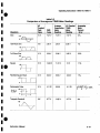
Comparison of Ave rage and TR MS Mete r Readings ......... ........... ....... ...... ..... ... ..................2-20
Function/ Range v.s. Range Numbe r ............... ....... .... ... ........... ........... ... .. . . .. ... ..................3-24
E rro r Query and Status Information ................................ ... ........... ....... ..... . ..... ... . .. ..... ...........3-32
Detailed Error L isting .. ... .... ......... .... . .......... ....... ............................ .....................::.......... .......3-33
1
1
ι
ι
ι
ι
ιι
DM 5110/DM 511
O perators Safety Summary
ι
The general safety information in this part of the summaη is forboth operating and servicing personnel. Specific
wamings and cautions will be found throughout the manual where they apply and do not appear in this summary.
TERMS
In t h is Manual
CA UTION statements i de ntify conditions o r practices t hat could res u lt in
p roperty .
d amage to t he e qu ipment o r ot h e r
WA RN I N G stateme nts i de n tify cond itions or p ractices th at coul d res u lt in pe r so n al i njury or loss of live.
As Mar ke d on Eq u i p men t
ι
ιι
ι
ι
ι
I
CA U TIO N i n dicates α pe rso nal i nj u ry h aza rd n ot imme diately accessible as one reads th e markin gs, o r α
haza rd to p roperty i ncluding th e i n st rume n t itself.
DA N G ER ind icates α pe rsonal injury hazard immediately as one reads th e mark i ngs.
SYMB O LS
In Th is Manual
Th is symbol in d icates where applica b le ca u tionary or oth e r i nformation is to be found.
T h is symbol in d icates static sensitive devices, t hat are subj ect to be damaged by static
elect r icity.
As Marked on Equi pment
DA N G ER - H ig h voltage
Protective grou n d (earth ) terminal .
&
Instr u ction Manual
ATTENTION - Refer to manu al.
DM 5110/DM 511
Safety Sum mary (con t.)
P O WER
CO N DITIO N S
U se th e Proper Power Cord
U se only t he powe r co rd and con n ector as specified fo r t h e i nst r ument .
Power Source
Use t h e pro p er p ower so u rce . Before switc h in g on, make s ure t h e i n st ru ment is set to t he voltage of t h e
powe r so u rce . Th is pro du ct is inte nde d to op erate from α power so ur ce t hat will n ot apply more t han 250
Volts RM S betwee n th e su pply con n ecto rs or b etwee n eit he r su pply connecto r an d g round. Α protective
gro und con n ectio n b y way of t h e gro u n d i n g co n necto r n t h e power cord is essential for safe op eratio n .
i
Grou ndin g the Product
Th is p rod uct is g ro und ed t hrou gh th e gro un din g co n nector of the powe r cord. To avoid elect rical shock ,
pl u g t h e p ower co rd into α p roperly wired receptacle b efore mak i ng any connections to th e product i n p u t
or outp ut te r minals . Α protective g round co n nectio n by way of th e g round co n nectio n is esse ntial fo r safe
ope r atio n .
Danger Ar ising from Loss of Ground
Up on loss of t h e protective-g ro u n d connection, all accessible co ndu ctive p arts ( i n clud ing knobs a nd
contr ols t h at may a ppear to be i nsulated ) can render an electrical s h ock.
U se t he Proper Fuse
To avoid fi re h aza rd , u se only t he fu se sp ecified fo r t h e i nstru me nt i n t h e i n stru ment part list. Α rep laceme n t f use m ust meet th e type, voltage rati ng, and current rati n g specificatio ns fo r t he f use t hat it replaces .
G ENER AL
Do Not Op erate in Explos ive Atmospheres
To avoi d exp losio n s, do not operate t h is instrument i n an atmosphe re,of ex p losive gasses.
Do
Not Remove Covers or Pa nels
To avoid pe rso n al i nj u ry, t h e instru ment covers or pan els sh o u l d only be removed by q u alified service
p e rsonnel . Do not ope rate t he i n strume n t wit h ou t cove rs and panels p ro pe rly i n stalled .
ν
Instruct ion Manual
Spec ifications - DM 5110 / DM 511
Secti on 1
S PECIFICATION
Introduction
Th is section of the manual contains α general
description of the Tektronix D M 5110 Programmable
Digital Multimeterand the DM 511(Νοη Programmable)
Digital Multimete rand complete electrical, mechanical,
physical and environmental specifications.
Stand ard accesso ries are also liste d.
-
In strument Description
T he setti ngs of the GPIB address and .terminator are
initiated by the frοntpanel keys.
-
Α BEEPER mode, wh ich sou n ds t h e beepe r when
α measurement is beyond u ser selectable HI and
LO L IM ITS.
FAST and N OR MAL mode measurement . (3.5 and
4 .5 digit)
50 and 60 Hz measurement modes.
The Tektronix DM 5110 is α p rogrammable six
Α manually op erated switc h can select α fr ont o r rear
function autorangίηg dίgital m ultimeter. At 4 1/2 d igitti
connecon toe
th LOW and Voltsempnputs.
/Ω /T
i
resolution, the LED
counts
display can present +/- 19,999
The DM 5110 /DM 511 can make the following basic
This switch is not ope rated via the ΙΕΕΕ-488.1 bus, but
α query is available in the comma nd set to monitor the
setting.
WARNING I
measurements:
10
ι
ι
ι
ι
ι
ι
ι
ι
-
DC voltage measurements up to 1000 V with
maxim um resolution of 10 mV.
Resistance measuremen ts up to 20 ΜΩ with
maxim um resolutio n of 10 mΩ
TRMS AC voltage measurements up to 500 V with
maxim um resolution of 10 mV.
DC current measu rements up to 2000 mA with
maximum resolution of 10 πΑ.
TRMS AC current measurements up to 2000 mA
with maximum resol ution of 10 ηΑ.
Tem perature measureme nts from -62 to + 240 °C.
(Tektronix Ρ6602 temperature probe required.)
All measurement f unctions can be set to either manual
o r auto-ranging exce p t for t h e tem p eratu re
measurement having just one range .
Besides the led's showi ng the measured val ue, 5
ad ditional indicators show NULL, H OLD and AUTO
and t he GPIB functions ADD R and REM .
The DM5110/ DM 511 has the following functions :
-
Additional d Bm and d BV ranges, which aresoftware
calculated versions of the AC voltage ranges.
Α NULL fu n ction to make measurements with an
offset value.
Α HO LD mode and α T RIGG ER function.
Α COMPARE mode, com p aring the measurement
with user selectable HI and LO L IMITS .
Instruction Manual
The maximum voltage that can be applied to the rear interface connection is limited because of safety
requiremen ts.
The DM511 has the same specs. as the DM5110, but
is not GPIB programmable, so all items in this manual
concerning the IEEE- 488 .1 bus do n ot apply to the
D M511 .
CAUTION
Turn the power OFF before inserting the DM51 10.
Otherwise arcing may occur at the rear interface
connectors and damage may be done to the plug-in
circuitry.
WARNING
Do NOT operate this product without covers or panels
installe d.
Do 'NOT, apply powe r to the plug-in via a plug-in
extender.
.
Do NOToperate this product with distorted covers.
To avoid fire hazard, only use the fuse specified in the
parts list.
The maximum frontpanel inpu t voltage is 1000 V peak,
so the in put connectors, and t herefore all mainboard
circuitry and part of the GPIB board , may be floati ng up
to 1000Volts.
1 -1
Ε
Specifications - DM 5110 / D M 511
IEEE 488 .1 Function Capability
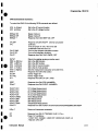
1 GPIB Reference Guide DM5110 ... ...070-7559-χχ
1 Instrument Interface Guide
DM 5110 .......................................:..... .070-7560-χχ
The built- in IEEE- 488 .1 interface makes the
DM 5110 instrument remotely p rogrammable via the
IEEE- 488 .1 bus as specified in
IEEE Stand ard 488 .1 - 1987, "Standard Digital
Interface for Programmable Instrumentation" .
In this manual the interface is called the General
Purpose Interface Bus ( GPIB ).
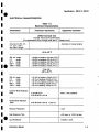
IEEE - 488 .1 INTERFACE FUNCTION SUBSETS
IEEE Standard 488 .1-1987 identifies the interface
function repertoire of α device on the bus in terms of
interface function s ubsets . These subsets are defined
in the standard . The subsets that apply to the DM 5110
are listed below.
Table 1-1
IEEE- 488 .1 INTERFACE FUNCTION SUB SETS
Note
The test leads ΡL260 (196-3212-χχ) are rated for
1000 V, based on UL evaluation.
Optional Accessories include :
Temperature Probe ....... ........... ....... .... . Ρ6602
H igh Voltage Probe ....... ....... .... ....... ..... 010-0277-χχ
RF Probe ........................... .. ..... . ....... . .. . Ρ6420
Service Manual .......... ...................... ..... 070-7479-χχ
Option
Option 02 : DM5110 (or DM511) calibrated with α
temperature probe P6602.
Performance Conditions
SH1
ΑΗ1
Τ6
Source h andshake. Complete capability.
Acceptor handshake . Complete capability.
Untalk if MLA
The characteristics in this specification are valid
with t he following conditions:
L4
Unlisten if ΜΤΑ
Service request . Comp lete cap ability .
Remote Local. Completecapability inclu ding
local lockout.
-
The instrument must h ave been calibrated at
an ambient temperature between + 22 ^C and
+24 ^C.
ΡΡΟ
Parallel Poll. Does not respond to parallel
poll
Device clear. Complete capability .
Device trigger with G ET
Non controller function
Open collector d rivers
-
The instrument must be in a non-condensing
environment whose limits are described u nder
Environmental .
-
Allow 30 minutes warm-up time for o peration
to the specified accuracy, and 1 h our after
exposure to or storage in h igh humidity
(condensing ) env ironment.
SR1
RL1
DC1
DT1
CO
Ε1
IEEE- 488.1 BUS ADDRESS AND TERMINATOR
T he GPIB address and terminator are stored in
EEPROM .
The address and terminator are set via the front panel,
as described in chapter 2.
Accessories and Options
Standard Accessories Included
1 DM5110 Operators Manual ........ .. 070-7478-χχ
1 Pair of test leads .............. ............. 196-3212- χχ
1-2
Specifications are valid only with t hose
connecti6ns to the instru ment that are required
to verify each specification .
Items listed in t he Performance Re q uirement column
of the following tables are verified by completing
the Performance Check in t he Service Manual .
Items listed in the Supplemental Information column
may n ot be verified in the manual ; they are
ex plainatory n otes for which no limits are specified .
Instruction Manual
Specification - DM 5110 / D M 511
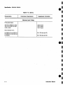
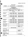
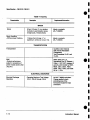
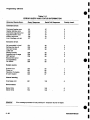
ELE CTR ICA L
CHARACTER ISTICS
Table 1-2
E lectrical Characteristics
Characteristics
Perfor ma n ce Requ irements
Supplemental Information
DIRECT VOLTAGE (DV)
(4.5 d igit, front and rear panel inpu ts)
[For specifications of t h e 3.5 digit mode, add +/- 1 d isplay count.]
'
ι
+18 to +28 °C
ι
lie
200 mV
2V
20 V
200 V
1 000 V
ι
range
ran ge
range
range
range
ra n ge
range
range
range
range
Common Mode Rejectio n
Ratio
N or mal Mode Rejection
ι
Ratio
'
"
t
t
t
t
t
(0.05%
(0.05%
(0 .05%
(0.05°/ο
(0.05%
of
of
of
of
of
reading +0 .015% of F.S.)
reading
reading
reading
read ing
+0.01% of F.S.)
+0.015% of F.S.)
+0.01% of F.S.)
+0.02% of F.S.)
0 to +18,
+28 to +50 °C.
200 mV
2V
20 V
200 V
1000 V
'
ι
Automatic o r manual ranging
Accu r acy for 200 m V,
2 V, 20 V, 200 V,
and 1000 V ranges
t
t
t
t
t
(0.15% of reading +0.04% of F.S.)
(0.1 % of reading +0.02% of F.S.)
(0.15% of reading +0.025% of F .S.)
(0.1% of reading +0.02% of F.S.)
(0.1% of r eadi ng +0.02% of F.S.)
z100 dB atDC
z 80 dB at 50 or 60 Hz
Wit h α 1 kΩ unb alance
z50d B at50or60 Hz (t0 .2 Hz)
Maxim um Resol utio n
10 μV
Step Response Time
< 50 msec. to 0.05 °/ο of ste p
Input Resistance
10 M O hm i 0.5%
Instruction Manual
1-3
Specificatio n -
DM 5110 / DM 511
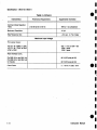
Ta b le 1-2 (Co nt .)
Ch aracter istics
Performance Requirements
Supplemental Information
Maximum Input Voltage
Front-panel inputs:
VOLTS Al /TEMP to LOW
VOLTS /Q /TEMP to GNb
LOW to GND
1000 V peak
1000 V peak
1000 V peak
Rear interface Conn.:
Pin 28Β (H i) to p i n 28Α (Lo)
Pin 28Β (Hi) or pin 28Α ( Lo)
to Chassis
60 V (DC plus pk AC)
60 V (DC plus pk AC)
Instruction Manual
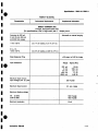
Specification - DM 5110 / DM 511
Table 1-2 (font.)
Performance Requirements
Characteristics
1
ι
Supplemental Informat i on
ALTERNATI NG VOLTAG E (AC coupled)
(Tru e RMS )
(4.5 digit, front and rear panel inputs)
[For pecifications of the 3.5 digit mo de, add +/- 1 disp lay count.]
s
Automatic or manual ranging
Accuracy for 200 mV
2 V, 20 V, 200 V an d
500 V ranges
+18 to +28 °C
1
200 mV to 200V Range
20 H z to 100 Hz
100 H z to 10kHz
10 kHz to 20kHz
20 kHz to 50kHz
i 0
ι
t
t
t
t
(0 .8%
(0.3%
(0.6%
(1 .0%
of
of
of
of
reading
read ing
read ing
read ing
+0 .05%
+0.05%
+0.05%
+0.05%
of
of
of
of
F .S.)
F.S.)
F .S.)
F.S.)
Input
Input
Input
Input
> 200 counts
> 200 counts
> 500 counts
>2000 co unts
t
t
t
t
(0.8%
(0.3%
(0.6%
(1 .0%
of
of
of
of
reading
rea ding
readi ng
rea d ing
+0.05%
+0.05%
+0.05%
+0 .05%
of
of
of
of
F.S .)
F.S.)
F.S.)
F .S.)
Input
Input
Input
Input
>
>
>
>
500V range
20 Hz to 100
100 Hz to 10
10 kHz to 20
20 kHz to 50
Hz
kHz
kHz
kHz
50 counts
50 counts
250 counts
500 counts
0 to +18,
+28 to +50 °C
200 mV to 200V Range
20 Hz to 100 Hz
100 H z to 10 kHz
10 kHz to 20 kHz
20 kHz to 50 kHz
t (1 .1 %
t (0 .6%
f (0 .9%
t (1 .3%
of
of
of
of
reading
read ing
read ing
read ing
+0.075%
+0 .075%
+0 .075%
+0 .075%
of
of
of
of
F.S.)
F.S.)
F.S.)
F.S.)
I n put
Inpu t
I n put
Input
> 200 counts
> 200 counts
> 500 counts
>2000 cou nts
t
t
t
t
of
of
of
of
rea ding
readi ng
reading
reading
+0.075% of
+0.075% of
+0.075% of
+0.075% of
F.S.)
F.S.)
F.S.)
F.S.)
Input
Input
Input
Input
>
>
>
>
500 V range
ι
ι
ι
ι
20 Hz to 100 Hz
100 Hz to 20 kHz
10 kH z to 20 kHz
20 kHz to 50 kHz
I nstruction
Manual
(1 .1%
(0.6%
(0.9%
(1 .3%
50 counts
50 counts
250 counts
500 cou nts
1- 5
Spec ification - D M 5110 / D M 511
Table 1 -2 (Cont.)
Character i stics
Performance Requ i rements
Commo n Mo de Rejection
Ratio
z 60 dB at 50 or 60 Hz
Supplemental Information
With α 1 kΩ unbalance
Maximum Resolution
10 μV
Step Response time
< 0.3 sec. to 1 % of step
Maxim u m Input Voltage
Front-panel in puts :
LOW
VOLTS / Ω / TEMP to GND
LOW to GND
VOLTS / Ω /TEMP to
500 V rms or 600 V DC
1000 V peak
1000 V peak
Rear interface Conn.:
.
_
. .
. .
.
.
.ι
ι C plus pk AC)
. ι V (DC plus pk AC)
Crest Factor
1- 6
Instruction Manual
Specificatio n -
D M 5110 / DM 511
Table 1-2 (Cont.)
1
1
ι
ι
ι
Characteristics
Per formance Requirements
Supplemental Informatio n
DECIBELS (AC coupled)
(True RMS )
(4.5 d igit, front and rear p a n el inputs)
For p ecifications of the 3.5 d igit mode, add +/- 1 d isplay count.
s
Acc uracy for d BV/dBm
00.00 d Bm= 1 mWatt in α 600 Ω load
00 .00 d BV =1 V RMS
Automatic or manual
r anging
+18 to +28 °C
Accuracy for d BV
(autoranging)
t 0.3 d B from -34 d BV to +54 d BV
t 0.6 dB from -54 d BV to -34 d BV
t 1 .0 dB from -60 d BV to -54 d BV
F requency 20 Η.τ to 20 kHz
F requency 20 Hz to 10 kHz
Freque ncy 20 Hz to 10 kH z
Accuracy for dBm
(autoranging)
t 0.3 d B from -32 dBm to +56 dBm
t 0.6 dB from -52 dBm to -32 d Bm
t 1 .0 d B from -58 d Bm to -52 d Bm
Frequency 20 Hz,to 20 kH z
Frequency 20 Hz to 10 kHz
F requency 20 Hz to 10 kHz
0 to +18,
+28 to +50 °C
ι
ι
Acc u racy fo r dBV
(autoranging)
t 0.4 d B from -34 dBV to +54 d BV
i 0.8 dB from -54 dBV to -34 dBV
t 1 .5 dB from -60 dBV to -54 dBV
Frequency 20 Hz to 20 kHz
F requency 20 Hz to 10 kHz
F req uency 20 Hz to 10 kHz
Accuracy for dBm
(autoranging)
t 0 .4 dB from -32 d Bm to +56 d Bm
i 0.8 d B from -52 dBm to -32 d Bm
t 1 .5 dB from -58 dBm to -52 d Bm
F req uency 20 Hz to 20 _kHz
F req uency 20 Hz to 10 kHz
Frequency 20 Hz to 10 kHz
Maximum Resolutio n
0.01 d B
Step Response time
< 0.3 sec. to 1 % of step
In put Impe dan ce
2 ΜΩ *1%
paralleled by < 50 pF
Maximum Input Voltage .,
Front-panel inputs:
VOLTS / Ω /
TEMP to L OW
VOLTS / Ω / TEMP to GNO
LOW to GND
Ι
500 V RMS or 600 V DC
1000 V peak
1000 V p eak
Rear interface Conn.:
Pin 28Β (Hi) to p in 28Α (Lo)
Pin 28 Β (Hi) or pi n 28Α (Lo)
to Chassis
ι
Instruction Manual
60 V (DC plus p k AC)
60 V (DC plus pk AC)
1-7
Specification - DM 5110 / D M 511
Table 1-2 (Cont.)
Character istics
Performance Requirements
O H MS
T
S upplemental Information
(4.5 d igit, front and rear panel inputs)
[For s pecifications of t h e 3.5 d igit mode, add +/- 1 d isplay count.]
Accuracy for 200 Ω, 2W,
20 W, 200 kΩ, 2 ΜΩ
a nd 20 ΜΩ ranges
Automatic or manu al
Ranging
+18 to +28 °C
Source cur. V max. at full scale
200 Ω
2 kΩ
20 kΩ
200kΩ
2 ΜΩ
20 ΜΩ
range
range
ra nge
range
range
range
t
t
t
t
t
t
(0.05%
(0.05%
(0.05%
(0.05%
(0.1 °/ρ
(0.1%
of
of
of
of
of
of
reading +0.02% of F.S)
reading +0.01% of F.S)
reading +0.02% of F.S)
reading +0.01 % of F .S)
reading +0.02% of F.S)
read ing +0.01% of F.S)
1 .0
1 .0
10
10
0.1
0.1
mA
mA
μΑ
μΑ
μΑ
μΑ
0.2
2.0
0.2
2.0
0.2
2.0
V
V
V
V
V
V
0 to +18,
+28 to +50 °C
So u rce cur. V max. at full scale
200
2
20
200
2
20
Ω
kΩ
kΩ
kΩ
ΜΩ
ΜΩ
range
t (0.25%
t (0.25%
range
t (0.25%ρ
range
t (0 .25%
range
1
t(
%
range
1
t(
%
ran ge
Step Response Time
of reading +0 .04% of
of reading +0.03% of
of reading +0.04% of
of rea ding +0.03% of
of rea ding + 0.04% of
of reading + 0.03% of
F .S)
F.S)
F.S)
F.S)
F.S)
F.S)
1 .0
1 .0
10
10
0.1
0.1
mA
mA
μΑ
μΑ
μΑ
μΑ
0 .2
2 .0
0.2
2.0
0.2
2.0
V
< 0.2 sec:
200 R to 2 ΜΩ ranges
< 2 sec: in 20 Mil range
Maximum in put voltage
any range (front)
300 V peak
M aximum input voltage
any range (rear)
60 V pea k
Maximum Resolution
10 ma
M aximum ope n circuit
voltage
<11 V
1- 8
V
V
V
V
V
Instruction Manual
Specificat ion - D M 5110 / D M 511
Table 1-2 (Cont.)
Characteristics -
Performance Requ i rements
Supplemental informat i on
DIRECT C U RRENT (DC)
(4.5 digit, front panel inputs only)
[For specificatio ns of the 3 .5 digit mo de, add +/- 1
d isplay count.
Automatic or manual ranging
Accuracy for 200 μΑ,
and 2000 mA rangesA
1
1
ιι
ι
ι
ι
ι
ι
I
+18 to +28 °C
Ι
t (0.1 % of readi ng +0.01 % of F .S.)
Oto +18,
+28 to +50 °C.
Ι
t (0.3 °/ο of reading +0.025 % of F.S.)
Step Res ponse Time
I
(
I nput resistance
I
I
< 50 msec. to 0.06 % of step
Ra nge
200
2
20
200
2000
μΑ
mA
mA
mA
mA
Approx.Res.
1 .0 kΩ
100 .0 Ω
10.2 Ω
1 .2 Ω
0.26 Ω
Maximu m Op en Ci rcuit
In put Voltage (mA to ιοωΙ
Ι
250 V peak
Maximum Inpu t Current
1
1
2 Α any range
I
, 1
Maximum floati ng voltage
mA to GND
LOW to GND
Maximum resolution
Instructi on Manual
1000 V peak
1000 V peak
10 ηΑ
1- 9
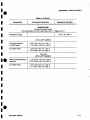
Specification - DM 5110 / DM 511
Table 1-2 (Co pt.)
Characteristics
Performance Req uirements
Supplemental Information
ALTERNATING CURRENT (AC coupled)
(True RMS )
(4 .5 d igit, front p anel inputs only)
[For specifications of the 3.5 digit mode, add +/- 1 d isplay count.]
Accuracy for 200 μΑ,
2 mA, 20 mA, 200 mA
an d 2000 mA r anges
Automatic or manual
ranging
+18 to +28 °C
+/-(0 .8% of reading +0.05% of F .S .)
+/-(0 .3% of reading +0.05% of F.S .)
20 Hz to 100 Hz
100 Hz to 10kHz
In put > 200 counts
Input > 200 counts
0 to +18,
+28 to + 50 °C
20 Hz to 100 H z
100 Hz to 10kHz
Ι +/-(1 .1 % of reading +0.075% of F.S.) Ι
+/-(0.6% of reading +0.075% of F.S.)
In p ut > 200 counts
Input > 200 counts
Crest F actor
/
1
3 : 1 for 0.1 °/ο add . error
Step Res ponse Time
I
Ι
< 0.3 sec. to 1 °/ο of step
Input Impedance
I
I
Range
200
2
20
200
2000
Maximum Open Circuit
Input Voltage (mA to LOW)
Maximum Input Current
Approx . Imp .
μΑ
mA
mA
mA
mA
1 .0
.kΩ
100.0 Ω
10.2
Ω
1 .2
Ω
0.26
Ω
250 V peak
1
1
2 Α any range
Maximum floating voltage
mA to GND
LOW to GND
M aximum Resolution
1- 1 0
_
I
1000V peak
-- 1000V peak
10 ηΑ
Instruction Manual
Specification -
D M 5110 / D M 511
Table 1-2 (Cont.)
Characteristics
I
Performance Requ irements
I
Su pplemental Information
TEMPERAT URE
r n t pa nel i n pu ts)
(4 .5 digit, f o
[For specificatio n s of t he 3.5 digit mo de; add +/- 1 display co unt.]
Temperatu re range
I
'
Ι
Ι
-62 ^C . to + 240 OC .
+18 to +28 °C ambient
n st ru me n t calib rated
to Ρ6602 p ro be
t 0.6 ^C f r om -62 ^C to +150 ^C
t 1 .6 OC f rom +150 cC to +240 ^C
An y Ρ6602 Pro be
t 3.5 OC f rom -62 *C to +150 ^C
t 6 oC from +150 oC to +240 cC
.
0 to +18,
+28 to +50 °C ambient
l
.
Ρ6602 Pr ob e calibr ated to
inst ru ment
t 1 .5 cC from -62 oC to +150 *C
t 2.5 *C f rom +150 ^C to +240 ^C
Any Ρ6602 Prob e
t 4.5 °C from -6 2 °C to +150 oC
f 7 cC from +150 cC to +240 cC
1
ι
ι
ι
ι
ιι
ι
ι
Instructio n Manual
1 -11
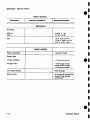
Specification - D M 5110 / DM 511
Table 1-2 (Co pt.)
Characteristics
Perfomnaηce Regυirernents
Supplernentel
information
M ECHANICA L
N et Weig ht
DM5110
DM511
2.45 l bs. (1 .1 k g)
2.2 lbs. (1 .0 k g)
Size
2.63 in . (66 .8 mm) W χ
11 .240 in . (285.3 mm) D χ
4.961 in. (125.9 mm) Η.
MISCELLA NEOUS
Power Consumption
Less than 10 watt
Rea d ing Rate
4.5 digit (NORMAL)
> 3 times per second
3.5 d igit (FAST)
> 25 times p er second
except 20 MOh m range
(10 times per second)
Over- range Indicatio n
blinking d isplay
Warm-up Time
30 minutes (60 minutes after
sto rage in h igh humidity
environment)
1- 12
Instruction
Manual
Specification - D M 5110 / DM 511
ι
ι
ι
ι
ι
ιι
ι
ENVIRON MENTAL C HARACTERISTICS
Table 1-3
E nvironmental Characteristics (with power module.)
Characteristics
Desc ription
Supplemental Information
T EMPERATURE
Meets or exceeds
MIL-Τ-28800D, class 5.. with
0 oC to +50 ^C
exceptio ns.
Non-Operating
- 55 oC to +75 °C
HUM IDITY
H umidity
5 95°/ε RH, 0 ^C. to 30 °C
5 75% RH 30 °C to 40oC
5 45% RH a bove 40oC
Meets or exceeds
M IL-Τ-28800D, class 5,
non-condensing .
ALTIT UDE:
4 .6 k m (15,000 ft.)
Non-Operating
Meets or exceeds
MIL-Τ-28800D, class 3.
15 km (50,000 ft.)
I
ι
ι
ι
ιι
ι
ι
VIBRATION
Vibratio n
Instru ction Manual
0.64 mm (0.025") peak-to-peak, .
5 Hz to 55 H z, 75 minutes .
<Refer to ΤΜ500 (DM511)
or TM 5000 ( ΡΜ5110) power
module specifications .>
M eets or exceeds M IL-Τ-28800D,
class 3, wh en installed in powe r
mod ule.
1-13
Specification- D M 5110 / DM 511
Table 1-3 (cont.)
Characterιsfics
SupplementalInfom ιetion
Descrlption
S HOCK
Shock
Bench Han d ling
<Withou t p owe r module.>
30 g's (1 /2 sine) 11 ms. duration,
3 shocks in each d irection along
3 major axes, 18 total shocks.
12 drops from 45 degr., 4" or
equilibrium, whichever occu rs first .
Meets or exceeds
ΜΙL-Τ 28800D .
Ι Meets or exceeds
MI L-Τ 28800D .
TRANSPORTATION
Transportation
Qualified und er National
EMC
Within limits of F .C.C.
Regulations P art 15, Sub part J,
Class Α ; VDC 0871 category Β
and M IL-461 Β (1980) for RE01,
RΕ02, CE01, CΕ03, RS01,
R S03, CS01, CS02, and CS06.
30 H z -1 GHz
Safe Transit Association
Preshipment.
Test Procedures 1A-B-1 and
1 Α-Β-2.
(System p erforma nce
s ubj ect to exceptions of
power module an d/or ot h er
plug-ins.)
ELECTRICA L DISCHARG E
E lectrical Discharge
Operating
1- 1 4
Ope rating Maximum Test Voltage :
20 kV, 150 pF throug h 150 Ω.
No MIL-T-28800 equivalent.
Charge applied to each
p rotruding area of the
front-panel except the input
con nectors .
Instruction Manual
ιι
ι
ι
Section 2
Ope rati ng Instructions - DM 5110 Ι DM 511
OP E R ATI N G I N ST RU CTIO N S
Int roduction
Power Up Sequence
T h is section provides installatio n a nd operati ng in-
When powered on, the DM 51101511 's micιoprocessors perfo rm α diagnostic routi n e (self test) to ch eck
the functionality of the EEPRO M and the DM5110
tests the communication between the GPIB board
mic rop rocesso r an d t he microprocessor of the mai nb oard.
The instrument will start in the DC Voltage, autoranging, 4.5 d igit acc uracy mode.
Th e LO LIMIT a n d ΗΙ L IM IT are set to zero.
The NULL, BEEPER and COMPARE mode are off .
If no EEPRO M errors are fou nd, the microp rocessor
goes on to c heck t he f unctionality of t h e ot h er instrument h ardware.
structions for t he DM 5110 / 511 an d d esc ribes t h e
functions of the front-pa nel controls and connectors .
T h e information i n t his section assumes the instrument
is not connected to the GPIB.
Complete informatio n fo r programming the DM 5110
via the GPIB (General Purpose Interface Bus) is in t he
Programmi ng sectio n of this manual . (see sectio n 3)
Installation and Removal
NOTE
The DM 5110 is designed to operate in αTM 5000 series power module.
The DM 511 ίs designed to operate ίη α ΤΜ 500- s471100
module and also in α TM 5000 - series powermodule .
The DM 5110/ DM511 are calibrated an d ready for use
when received. It operates in one compartment of α
power - module ( TM 5000 or ΤΜ500 is depe nding on
t he type of in strume nt, DM 5110 or DM 511) .
Refer to the manual of your power module for line
voltage re quirements and power module operation .
ι
CAUTION
To prevent damage to the DM5110 /DM 511, turn the
power module offbefo re installation or removal.
Do not use excessive force to install or remove.
B efore installing the instrument in the power module,
align t he instrument chassis with the u pper and lower
g u ides of the selected compartment. Press the instrument in and firml y seat the circuit b oard in the interconnecting jack.
To remove the instrument, pull the release latch (located in the lower left cor n er of the fro nt p anel), until
the interconnecting jack disen gages and the instrument sli des out.
Ch eck that the instrument is fu lly inserted in the power
mo dule .
Instru ction Manual
If an EEPROM error is found , an erro r code "ΕΕrr" is
d isplayed in the front-panel display for about α second. In t h at case, t he IEEE address is t h e n set to 15
and the line frequency to 60 H z.
If the internal mic roprocesso r communicatio n test fails,
the instrument - reacts like α DM511 . This can be
checked by p ressing the INST ID key ; α DM511 will
n ot show α GPIB ad dress. Also t he internal d iagnostic
LED on the GPI B-board of α DM5110 will n ot blink in α
constant rate with α one second repetition time.
When errors like described above occur, send you r
in strument to the nearest Tektro nix Service Center.
WA RNING
Dangerous arcs of an explosive nature in a high
energy circuit can cause severe personal injury or
death.
If the meter is connected to α high e nergy circuit
when set to α current range, low resistance range or
any other low impedance range,the meter is virtually shorted.
Dangerous arcing can also result when th e meter is
set to α voltage range if minimum voltage spacing is
reduced, or ifmaximum input voltages are exceeded.
The maximum input common- mode voltage(the voltage between the LOW, V/Ω/ΤΕΜΡ, mA - inpu t and
chassis ground) -4A00 V peak. Exceeding thίs
value may create α shock h azard.
Ι
ι
Operating Instru ctions - DM 5110 / DM 511
Repackagi ng for Sh ipment
It is recommended that t h e or igi n al carton an d packi n g
mater ial be saved i n the eve nt it is necessary fo r the
i n st rument to be res hipped to α Tektro nix Service
Cente r, usi n g α commercial tra n s port carrie r. If the
o riginal mate rial is unfit or not available, t h en repac k age the instrument u si n g the followi n g proce dure :
1.
2.
3.
Completely wrap t he i n st rume nt with polyeth yle ne sh eeting or equivalent to protect th e outsid e finish and prevent e ntη of h armf u l s ubsta n ces i nto the i nst ru ment .
4.
Cu s h io n th e in strument on all si des u sing eig h t
cm of paddi ng mate rial or urethane foam, tig htly
packed between t h e carton and t h e i nstru ment.
U se α co rru gated cardboard sh ippi ng carton
h avi ng α test st rength of at least 125 kilo an d
wit h an i n side d ime nsion of at least fiftee n cm
large r th an the instru me n t d imension s.
If t h e instr u ment is goi n g to be sh i pped to α
Te kt ronix Service Ce n ter , enclose the following
i n for mation :
Seal the carto n wit h an i n dust rial stapler o r
s h ippi n g tap e.
6.
Ma rk the add ress of th e Tekt ron ix Service Cente r and also yo ur own address on the s hip ping
carton in two prominent locations .
- The ow n ers add ress, n ame, pho ne number of
α contact pe rso n .
- Type, optio n nu m ber and se rial number of the
i n strume nt, reason for ret urning and α complete descri ption of the service re qui red .
1
ιι
ι
Α
ι
ι
ι
ι
2-2
Instruction , Manual
ι
ι
O perat ing Instructions- D M 5110 Ι D M 511
ι
ι
ι
ι
ι
ι
ι
ι
ι
ι
ι
ι
ιι
ι
ι
r- X60100~~00
R
~i~ia
ADDIt
ο
_ _ ι
,
YW~iLLZS.J~'~
_ι. 1_1. 1_1. d
Λ[Λ
Yll
___
~~
UΓG
~
W.u,tl.
k
V
t~ι~
Ή
Ιί
Ιί
ο
ο
ο
2
π ί~ί
' ΟίΈ9ίΟm,
~..._....~.._
iι
k t - ίι , ιι rκ
Ή
.._._ =.
ιιιr~ι"~.
~τ
τ
91ro
f,
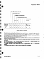
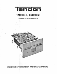
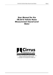
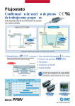
Fig.2-1 F ront Panelcontrols, con nectorsand indicato rs.
Instruction Manual
2-3
Operati n g Instructions - DM 5110 Ι DM 511
Controls, Connectors and I ndicators
All cont rols, connecto rs a n d i ndicato rs required for
operation of the i n strume nts αιe located οη the front
pan el. Fig 2.1 s h ows the location of all cont rols, connecto rs and indicators .
dB
Illu minated w h en un its are in d eci Bells.
oC
Ο
P
ο
Display
olarity
LE D readout indicating t he polarity of the
measureme nt.
u mi nated w h en un its are
Ill
Celsi us.
in degrees
( Dio de )
41/2 - digit LE D readout with properly
position ed decimal poi n t.
Ill u mi nate d in 2 kΩ, 200 kΩ and 20 Mil
ran ges, in dicati ng d iode measurement
capabilitity i n t h ese ranges .
Ω
Ν (
Ill uminated whe n un its are in Oh ms.
. 112
Il u mi n ate d whe n un its are in k iloOhms.
Nrl
Illu minated w h e n un its a re i n M egaOh ms.
Beeper
Illu minated w h en the i n st rument is i n
the Beeper mode.
Beeper soun ds when t h e measure me nt is
below the LO limit or above the HI limit .
Ill u mi nated wh en u nits are i n μΑ.
ηιΑ
Ill u minated whe n un its are in mA.
Sinewave )
Illuminated in AC measuring mo des.
Up
Primary level:
Selects the n ext hig her measu reme n t
range. Pushing UP an d DOWN simultaneo u sly selects au toranging .
Seco n dary level:
Changing setti ngs.
Down
Pr imary level:
Selects the n ext lower measurement
range. Pus hing UP an d DOWN simultaneo u sly selects autoranging .
Seco ndary level:
Changi ng setti ngs.
H O LD
Primary level:
Ill u minate d when units are in Vohs or
combine d with d B for dBV.
m
Ill uminate d whe n units are in mVolts
(10 -α ) or combine d with dB for dBm .
2- 4
Pressing t h e key sets th e instr ument in
t he HOL D mode. T h e H O LD led is on.
Also i ndicati n g t hat the second ary fu nctio n s fun ctions can be u sed .
Seco ndary level:
Pressin g t h e key sets th e instr u ment i n
th e RUN mo de and ret ur ns the k eyboard
f unctions to the p r imary level.
I n str u ction Manual
Operati n g Inst ruction s -
ι
DM 5110 / DM 511
0
'
19
INST ID
OHMS
Primary level:
Pressing the key makes the instrument
s how h is primary address on the display .
Releasing the key makes the inst rument
return to the original state.
Secondary level:
Pressing the key sets the instrument in
the GPI B settings mode.
Primary level:
Pressing the key sets the instrument in the
Oh ms f unctio n.
Secondary level:
Pressing the key sets the instrument in the
Temperatu re function .
DCV
Primary level:
Pressing the key turns the NULL mode on
or off .
Secondary level:
Pressing t h e key sets th e i nstrument i n t h e
LO LIMit setting mode.
Primary level :
Pressing the k ey sets the instrument in
the DC voltage mode.
Secondary level :
P ressing the key triggers the instrume nt
21
l ie
DCA
Primary level:
P ressing t h e key sets the instrument in the
DC current function.
Secondary level:
Pressing the key will set th e in strument
in the 50 or 60 Hz setting mode.
NULL
dBm
Primary level :
Pressing the k ey sets the instrument in the
dBm function.
Secon dary level:
Pressing the key sets the instrument in the
COM Pare setting mode.
dBV
ι
ι
ι
ι
Primary level :
Pressing the k ey sets the instrument in the
AC current fu n ction.
Secondary level:
Pressing the k ey sets the instrument in the
3.5 or 4.5 digit setting mod e.
ACV
Primary level:
Pressing the key sets the instrument in the
AC voltage function .
Secondary level:
Pressing the key sets t he in strument in the
Beeper setting mode.
Primary level:
Pressing the key sets t he in strume n t in t h e
dBV functon.
Secondary level:
Pressing the key sets the instrume nt in the
H igh LIMit setting mode.
mA (Input)
Te rminal u sed in conjunction with the LOW
input connector for curre nt measu rements.
LOW
Common terminal for all types of measurement.
V/11 /TEMP(Input)
Terminal used in conjunction wit h the LOW
input connector for voltage, resistance and
tempe rature measureme nts.
Instruction Manual
2-5
Operating Instructions - DM 5110 / DM 511
32
Ground Terminal
REM ( led )
Chassis ground terminal .
Illuminate d w hen the instrument is in the GPIB
remote state .
AUTO ( led)
Illuminated in A U TO ranging .
Note :
This led is blinking constantly, when the inter
nal jumper is in the CAL position. TAKE CAREII
The instrumentcan now easily be recalibratedifil
Contact qualified service personnel!
H OLD (led)
Illumi nated when the H OLD mode is on and also
in d icating secondary keyboard level.
n
36
ADDR (le d )
Illuminate d when t he instru ment is bei ng GP I B
' addressed to talk o r listen.
INPUT (switch)
Selects the F RONT or REAR connection of the
LOW and VOL TS /Ω /TEMP inputs. In the REAR
position the front-pan el mA, LOW a nd
VOLT /Ω /TEMP - jacks are disconnected from
the instrument .
NULL (led)
Illumi nated when t he NULL mode is on.
2-6
In st ruction Manual
Operating Instructions - DM 5110 / D M 511
FRONT P ANEL O PERATION
General
In this section of the manual you will find α description of the front-panel operation of the DM 5110.
(See Fig . 2-1 )
The name of keys that are to be pressed are surrounded by square brackets [ ] wherever possible .
Example : the H ol d key would be written as [HOLD] .
Display
ι
ι
ιι
ι
ι
ι
The DM 5110 u ses α 4.5 digit LED 7 segment d isplay, combined with 17 separate LED's .
The display can have the following information :
The current (or last) read ing .
If an error situation occurs, the display will
show an error message for α short period of
time .
If the ID button is pressed , the GPIB address
and terminator are d isplaye d as d escribed on
page 2.9
If one of the set modes is selected, the display
will hold the value to be changed or other
information /prompts, needed to complete the
information transaction with the instrument .
GPIB Indicators
T here are two GPIB indicators on the front p anel:
The remote indicator . This indicates when t he
instrument is in remote state (REM) .
The addressed in d icator. This indicates when
the instrument is b eing ad dressed to talk or
listen (ADDR) .
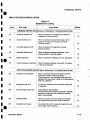
PRIMARY LEVE L FUNCTIONS
F rom the "RUN" mode the following functions can
be selected by h itting just one key
MEASUREMENT FUNCTIONS
Function
Key-sequence
Display
DCV
DCA
[DCV]
[DCA]
mV or V
μΑ o r mA
ACV
[ACV]
[ACA]
1~. and mV or V
- and μΑ or mA
OHMS
dBV
[Ω ]
[dΒV]
Ω, !Ω or ΜΩ
dBV an d
d Bm
[ d Bm]
dBm and
ACA
General
In all the functions, α measurement can be done in
manual or the autoranging mode.
In the display, the autoranging mo d e will be indicated by the "AUTO"-led.
The front-panel of the DM5110 h as twelve "soft" keys that enable the operator to select functions and
ranges of the DM .
An additional switch below the L OW and Volts /Ω /
TEMP jacks, selects the FRONT'or REAR connection of the LOW an d Volts/Ohms inputs.
The first time an [UP] or [DOWN] key is h it in t he
autoranging mode, the DM will r emain in the current
r ange, but the autoranging mode is turned off.
In this manual ranging mod e, the [DOWN] key selects α more sensitive range, and t he [UP] key will
make the DM c hange to α larger range.
FRONT PANEL CONTROLS
'
In the REAR position of the switch, the mA - j ack is
disconnected from the instrument, but the diode
bridge clamping circuitry, in series with t he fuse,
remains connected between the frontpanel LOW and
mA - j acks. This prevents that pushin g the FRONT/
REAR switch opens α circuit in which α currentmeasurement is taken. The switch can not b e controlled by the GPIB - bus. Α q uery in t he IEEE- 488 .1
instruction set is provided to r ead the status of the
FRONT/REAR switch.
Most function a nd range settings of the DM5110
can b e d one by single key operations. (PRIMARY
FUNCTIONS). These functions are indicated by α
large b lack texture above the keys .
By selecting the "HOLD" mode, another set of functions becomes available to the operator . (SECONDARY FUNCTIONS) . These functions are indicated
by text beside the keys.
Instruction Manual
the
2-7
Operating Instructions - DM 5110 / DM 511
Return to the autoranging mode is possible b y pushng the [UP] and [DOWN] k ey simultaneously .
Overrange is ind icated by blinking of the display.
At α reading of 20000 counts or more the d isplay will
show 19999.
Resistance [Ω ]
i
DC
V oltage
In the Resistance (Ω) mo de, six ranges, full scale,
are available :
200
2
[DCV]
20
200 .
In the DC V oltage (DCV) mode, five ranges , full
2
scale, are availab le :
200
2
20
200
1000
20
mV
V
V
V
V
Ω
kΩ
kΩ
kΩ
ΜΩ
ΜΩ
In the 2 W, 200 kΩ and 20 ΜΩ range, the output
voltage at full scale is 2 Volts, enabling the u ser to
make d io de measurements . Therefore, the diode
symbol is "on" in t hese three ranges.
D BM [dΒV] / [dBm]
DC Current [DCA]
DBV or
In the DC Current (DCA) mode, five ranges, full
scale, are available :
The DBV and DBM ranges are recalculated versions
200
2
20
200
2000
of the ACV measurements . Therefore, the five ranges
are also 200 mV, 2 V, 20 V , 200 V and 500 V true
RMS, full scale.
In the dBV mode these ranges are :
μΑ
mA
mA
mA
mA
-60 .0 ...... .......,.
-40 .0 .. .............
-20.0 .. ... .... ......
0 ........ ....... ... ...
+20 .0
AC Voltage [ACV]
In the AC Voltage (ACV) mode five ranges, full scale,
(true RMS), are available :
200
2
20
200
500
mV
V
V
V
V
-57 .78 ..............
-37 .78 .......... ....
-17 .78 ... ....... ....
+2.02 .:......... . ....
+42 .22 ......... .....
In the AC Current (ACA) mod e, five ranges, full
scale, (true RMS), are available :
μΑ
mA
mA
mA
mA
'
2- 8
-11 .76
+ 8.24
+28 .24
+48 .24
+56 .20
',
dBV
dBV
dBV
d BV
d BV
(00 .00 dBV equals α voltage of 1 V RMS)
In the dBm mode these ranges are:
AC Current [ACA]
200
2
20
200
2000
-13 .98
+ 6.02
+26 .02
+46 .02
+53 .98
ι
ι
ι
ι
ι
d Bm
dBm
d Bm
dBm
dBm
(00.00 dBm equals 1 mWatt in α 600 W load
(0 .775 V R MS)) .
It is advisable to use the dB ranges in autoranging
mod e, to insure measurements are taken in α range
where the best accuracy is achieved.
If α measurement is less then 1 °/ο of full scale, and α
more sensitive range is available, the u ser is notified
b y blinking of the sign le d . Overrange in the dB
ranges is shown by the blinking maximum value of
that range. Α zero counts measurement is converted to α -199.99 reading .
Instruction Manual
ί
ι
ι
ι
ι
ι
Operati ng I n structi ons. - DM 5110 Ι DM 511
'
NUL L Mod e
I N ST ID
To p rovide the ability to make relative measurements, the NULL mode is made available in all functions.
Το use the NULL mode , first select the desired function and range, then apply the offset measurement
to the instrument, and press the [NULL] k ey.
The present reading will become the null value.
The "NULL" led will indicate that the display-value is
relative .
Α special situation exists, when the NULL mode is
used in the d BV a nd d Bm function .
The V or m led is blanked indicating that α relative
measurement is made.
After selecting the NULL mode each range can be
selected, even autoranging .
Pressing the [INST ID] key will make the DM s how
it's primary address on the display and, if U SER has
been e nabled, generate α Service Request (SRO)
the G0113
.
The far right decimal point lights if the LF/ΕΟΙ mes'j" terminator is selecte d; decimal point does n ot
sage
light for ΕΟΙ ONLY selection .
R eleasing the key w ill make the DM5110 return to
the original state . The DM511 will n ot react to the
[INST ID] switch.
NOTE:
The absolute ηυΙΙ value will be subtracted from the
actual measureme nt. Blinking of the display, meant
to sho w overrange, is still determined by the actual
measurement value.
The NULL mode will not be accepted when the instrument is in overrange condition . (The d isplay will
briefly show "????")
When the p resent reading, pushing the [NULL] key,
is zero, the NULL f unction will not react.
If the result of the NULL function calculation exceeds the 45
. digit capabilities of that specific range ,
the decimal point will be shifted one position to the
r iht
g , an d th e least s ign ifit
g t w ηο longere
can diiill
b
shown in the display .
I
Example :
Suppose the NULL mode was set in the 2000.0 mA
DC Current range at +1900 .0 mA.
When t he same current in the opposite direction is
measured, (-1900.0), the display will show -3800
mA
'
,,r
During the N ULL mode the [HOLD] and [TRIG]
mode will still function. Any k ey except [UP], [DOWN],
[ID] or [HOLD] will make the instrument leave the
NULL mode, and t he null value will be lost.
H OLD Mode
At power up the instrument will be measuring constantly .
By pressing the [HOLD] key once, the instrument
stops measuring and displays the last measurement .
The "HOLD" - led will show that the instrument is in
the H OLD mode.
Pressing the [HOLD] k ey α second time will make
the instrument return to the RUN- mode. (secondaη
function [RUN])
The H OLD mode is also u sed as an entry to the
SECONDARY LEVEL.
When α k ey, that is not defined as α secondary
level, is pressed, the instrument will n ot react.
S ECONDARY LEVEL FUNCTIONS
Ι
Introduction
Except for Trigger and the selection of the Temperature function, all secondary level keyboard func-
tio ns are settings. In general, the function keys give
the ability to show settings on the d isplay . Changes
to settings can only be made with t he [UP] and
[DOWN] keys.
Changing from one setting to another can only be
done by leaving and re-entering the "HOLD" mode
(with most of the functions) .This is done to prevent
settings to be changed erroneously .
An exception is made for the BEEPER, COMPARE,
LO L IM IT and HI L IMIT settings. For ease of operation, it is possible to change from one of the settings
mentioned above, to one of the other t hree immediately.
Instruction Manual
2- 9
Operating Instructions - DM 5110 / DM 511
In DCV, DCA, d BV, d Bm and TEMP the limits can
h ave positive or negative polarity.
When the instru
ment is in the H OLD mode, the u ser
In
ACV, ACA and O HMS the limits can only be
can make one meas urement and return to the H O LD
positive.
mode automatically, just by pressi ng the "TRIG" key
on ce .
Beeper Mode
Trigger
Limits
'
The DM5110 h as an u ppe r (ΗΙ L IM IT) and α lower
limit val ue. (LO L IM IT)
At power-up, these will b oth be set to the zero
position . (0.00 °C, 0.00 d Bm or d BV) .
Related to the " limits" are the BEEPER and COM PARE mode.
Note :
There is only ONE upperand ONE lowerlimit, which
(once set) are related to the function in which they
were set
The settings remain stored in memory until, in α
function other then the one in which the current
limits were set, the limits are changed, or the COMPARE or BEEPER mode is chosen .
E xample :
An ope rato r wants to make measurements on 1 °/ο
10 kOhm resisto rs.
After selecting the 20 kOhms range the LO and HI
limits can be set to 9.900 and 10.100 k Ohms in the
secondary functions LOLIM and H ILIM .
After selecting the COMPARE mode, the [RUN] key
will enable the operato r to make measurements .
If an interruption occurs, he still can make oth er
measurements like voltage, current, temperature or
nor mal mode resista nce measureme nts, with out
distu rbing the limits, and afterwards return to measure
10 kΩ resistors immediately .
As soon as the limit setting, COMPAR E or B EEPER
on/off functions a re selecte d in α function d ifferent
then O h ms, bot h limits will be reset to their defa ult
value 0000.
It is possible to set the LO and HI limits in two
d iffe rent ranges of the same function and use the
COM PARE or BEEPER mode in autoranging.
2- 1 0
If the instrument is in t he BEEPER mode, indicated
by t he " ))))) " led, the beeper will sound when the
measurement is below the LO L IM IT or above the HI
L I MIT. An exception is made in the Ohms mode,
when t he HI L IM IT is set at 19999 in t he measurement r ange, and the instrument is in overra nge.
Selecting the BEEPER mode can be done b y first
pushing the [BEEP] key, wh en in HO LD mo de.The
d isplay will show "beep" .
The Beeper-mode can be switched on o r off, by
p ressi ng [UP] o r (DOWN] key.
All t he other keys except [UP], [DOWN] , [RUN],
[CO MP], H I LIM] and [LOL IM] will b e ignored.
The last measurement that was made before the
H OLD mode was entered , will be recalculated.
If the BEEPER mode was turned on, and t he value
is beyond t h e limits t he bee per will sou nd for α
moment.
When the key - sequence h as been completed, t he
instrument is still in the H OLD mode (indicated by
the H OLD led).
Only after pressing [RUN] the instrument will make
n ew measurements.
Selection of α different measurement function will
automatically turn off t h e BEEPER mode.
Continuity Measurement.
Whe n th e limits are set in α function different from
Ohms, and the Beeper mode is turned on while
measuring Oh ms, the limits will not return to the 0.0
settings. In that sp ecial case, the LOLIM IT will be
set to 10.00 Ω and the H ILIM IT to 19.999 ΜΩ.
Th is feature will only ap ply to keyboa rd commands
while the instrument is not in the remote state . (applies to DM 5110 only)
From t he power up condition, the contin uity mode
can be entered by pus hing [OHMS], [HOLD], [BEEP],
[UP ],an d [RUN] . In this setting the B eeper will sound
when the measurement is less than 10 Ω.
Instruction Manual
Ope rati ng Instructions - DM 5110 / DM 511
Setti ng
'
L imits
L IMIT setti ng can b e d one in the following way :
Press the [HOLD] key followe d by the [ΙΟL1Μ]
key to reac h the LO L IMITsetti ng mode.
The d isplay will show the cu rre nt LO L IMIT value.
'
l ie
Th e limit value will be in the same range and function in which t he instrument Was set befo re entering
the H OL D mode.
If limits were availa ble in memory of α completely
diffe rent fun ction, b ot h limits will be reset to ze ro,
the very moment the limit setting mode is entered.
Βγ using the [UP]- and [ DO WN]- k eys, t h is value
can be incremented or decreme nted.
The counting of t h e limit val ue will speed up as the
user h olds the [UP] - or [ DOWN] - k ey.
T h e DM 5110 will n ot allow the L O L IM IT above the
HI L IM IT or t he H ILI MIT below t h e LO L IM IT.
When, for instance an "up" goi ng LO LIM IT reaches
the H ILIMIT value, the HI L IM IT will also be incremented in t he same rate as the LO L IM IT.
T he user will be n otified by α "beep" from the bee per.
E xamp le:
ι
If the limits are to b e set from d efa ult value to 10 and
12 kΩ, it is efficie nt to set t he lo-limit to 10 kΩ first .
Th e n th e Hi-limit just h as to be changed from 10 to
12 kΩ..
Wh en th e d esired setti ng is reached, exit from the
L O L IM IT function is possible by p ressing :
[HI LIM]
[COMP]
[BEEP]
[RUN]
to set HI L IM IT,
to the COMPARE mode,
to th e BEEPER mode setti ng,
retu rn to previo usly selected function.
Other keys do not react.
The u ser can also start with the HI L IMIT setting by
p ressing [HOLD] and t he [H ILIM] k ey and afterwards
adju st the L O L IM IT.
Du ring all these procedures, the inst ru ment will b e
in H OLD mode, and this will be s hown by the
"HOLD" - led in t he disp lay area.
E very time the fu n ction is changed within the H OLD
mod e, th e last measurement that was made before
the H OLD mode was entered, will be recalculate d.
Instructi on Manual
The d isplay reading value is adju sted to the new
settings.
Only after pr essi ng [RUN], the inst ru me nt will make
new measureme nts.
To ch a n ge t h e range, the 50/60Ητ, the 3.5D/4.5D
or the IEEE settings, the user h as to leave the HOLD
mode first (RUN-key) . The reason is, to p revent settiηgs to b e changed e rroneously.
Com pare
Another feature, related to the limits, is the COMPARE mode, wh ere th e display will s h ow "HI", "L O"
and "PASS":
"LO" is shown when the measurement is b elow the
LO L IM IT,
"Hi" is shown when the measureme nt is more than
t h e HI L IMIT.
In all other cases the display will show "PASS".
During positive ove rrange the "Hl" will
negative overrange the "LO" will blink.
b link, during
Selecting the COMPARE mode can be achieved by
first pushing the [COMP] key, when in H OLD mode .
The d isplay will show "Comp".
Th e CO MPA RE mode can be turned "ON" o r"O FF"
with the [UP] and [DOWN] keys. When the COMPARE mode is turned "ON", t he last measu reme n t
that was made before the HOLD mode was entered,
will b e recalculated, and the dίsρΙαy reαdίηg ωίΙΙ be
"HI", "L O" or "PASS".
If the COMPARE mode is turned "OFF", th e reading will return to the normal decimal val ue.The instrument is still in t h e H OLD mode (indicated by the
HOLD led). Only after p ressing [RUN] the instrument will make new measurements in either the
COMPARE mode or t he 6ormal m ode.
During t h e COMPARE setting mode the following
modes are available by pressing:
[LOLIM]
[HILIM]
[BEEP]
[RUN]
to set LO LIM IT
to set HI L IMIT
to the BEEPER mode setting,
continuous measurement
Ι
-
Other keys do n ot react.
2- 1 1
Operating Instructions - DM 5110 / DM 511
To change the range, the 50/60Hz, the 3.5D/4 .5D or
th e G PIB setti n gs, th e u ser has to leave t h e H OLD
mode first ([RUN] - k ey) . This is to p revent settings
to be changed erroneously.
After pressing [RUN], any primary level key, (except
[HOLD, UP, DOWN o r I NST ID]), will make the instrume nt leave the COMPARE mode automatically .
If the COMPARE mode is combi ned with the beep
mod e, the beeper will sou n d at "H I" and "LO".
If the COMPARE mode is combined with t he NULL
functio n, the limits are compare d with t he resulting
val ue .
The [RUN] key will make the instrument leave the
3.5/4.5 set mode and proceed n the selecte d resolution .
Any other key d oes not react.
Th e 3.5 digit mode enables faster response
measurement. It is made visible as the least significant digit is b lan ke d .
In the 3.5 d igit mode COMPARE, NULL a nd BEEPER
modes are still valid.
Temperature Measurements
Pressing the [HOLD] and t he [G PIB] k ey will make
the instrument show the primary GPIB add ress setting in the d isplay [Adxx] .
The [UP] and [DOWN] k eys enable t he user to increme n t a nd decreme nt to an alternative add ress setting.
The other keys that will react, are:
Pressing the [HOLD] and [TEMP] key will put the
instrument in the tem perature measuring function .
In this case the DM5110 will n ot remain in the HOLD
mo de, but will automatically go to the RUN mode.
The temperat ure mode h as just o ne range.
The read ing is in deg rees Celsi us, from - 62.0 °C to
+240.0 °C with α 0.1 degree resolution.
The d isplay will s h ow "Open" w hen overrange
( > 250 .0 °C ) occurs and α b linking - 62.0 °C
reading, when t he temperature is exceed ing the
minimum val ue. Also when α valid measurement is
taken above the maximum temperature of the Ρ6602
cable (+230 °C), the d isplay will b link.
DM M Settings
Pressing t he [HOLD] and [50/60Hz] key will make
the instrument show the 50 or 60 H z setti ng in t he
d is p lay. The setting can be changed with the [UP]
and [DOWN] keys.
The [RUN] key will ma ke the instrument leave the
50/60 Hz setting mode and store the new value in
EEPRO M .
Any other key d oes not react.
i
GPIB Setti ngs
[RUN], to save the corrected GPIB add ress, or
[G P IB], to procee d to th e next GPI B fun ctio n;
the LF/ΕΟΙ setting . In this function, the display will
show "LF" or "ΕΟΙ " in t he d isplay.
The setting can be changed with the [UP] and
[DOWN] keys.
The other keys functio ning, are ;
[RUN], to save all GP IB settings in EEPROM, or
[GPI B] to return to the address setting mo de.
Α G P IB message can be terminate d in two
ways :
- ΕΟΙ Mode .
only.
d ifferent
The instrument terminates on ΕΟΙ
- LF Mode . When the instrument is in the LF mode,
α LF or ΕΟΙ in the input stream will terminate the
message .
At power-up the D MM will be in the 4.5 digit mode.
Pressing the [HOLD] an d t he [3.5/4.5] key will make
the instrument sh ow 3.5 or 4.5 in the display.
The setting can be changed with t he [UP] and
[DO WN] keys.
2- 12
Instruction Manual
ι
ι
ι
ι
ι
Operating Instructions - D M 5110 / DM 511
'
I *
θ
θ
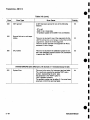
Summary of
Keyboard
Functions
The followi ng keyboard sequences start from the normal "RUN" measuring mo de.
Table 2:1
Su mmary of Key b oard
Fu nctio n s
Sequence of keys to be pressed
Function
I
B asic measurement functions Resista n ce
[Ω]
DC Voltage
[DCV]
AC Voltage
[ACV]
AC Voltage dBm
[dBm]
AC Voltage dBV
[dBV]
DC Current
[DCA]
AC Current
[ACA]
Te mperature
[HOLD], [TEMP] .
Autoranging O FF
[UP] or [DOWN]
More sensitive range
[DOWN]
H ig h er
[UP]
ra
n ge
-
Autoranging ON
[UP]and [DOWN] simultaneo usly.
Stop measuring
[HOLD]
M ake one measu rement
[HOLD], [TRIG].
ι
ι
I nstru ction
Manual
2- 13
Operating Instructions - D M 5110 / DM 511
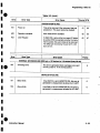
Summary of
k eyboard functions ( Cont. )
Table 2.1 ( Cont . )
Function
Ι
Sequence of keys to be pressed
DMM setting functions
Set linefreq. ,to 50Hz
[HOLD], [50/60 Ητ], [UP] or [DOWN], [RUN].
Set linefreq. to 60Ητ
[HOLD], [50/60Hz], [ UP ] or [DOWN, [RUN] .
Select 3.5 digit mo d e
[HOLD], [3.5/4.5], [UP] or [DOWN], [RUN] .
Select 4.5 digit mode
[HOLD], [3.5/4.5], [ UP ] o r [DOWN, [RUN] .
NULL mo de ON
[NULL]
NULL mode OFF
[NULL] or any Function Key
Set LOLIMIT
[HOLD], [LOLIM ], [UP] or [DOWN], [RUN] .
Set H ILIMIT
[HOLD], [HILIM], (UP ] or [DOWN], [RUN] .
COMPARE-mode ON
[HOLD], [COMP], [ UP ] or [DOWN], [RU N].
COMPARE-mode OFF
[HOLD], [COMP], [UP] or [DOWN], [RUN] or any Function Key .
BEEPER-mode ON
[HOLD], [BEEP], [ UP ] or [DOWN], [RUN] .
BEEPER-mo de OFF
[HOLD], [BEEP], [UP] or [DOW N], [RUN] or any Function Key.
-
GPIB setting functions (DM5110 only)
GPIB Service Request
[INST ID]
Select GPIB address
[HOLD], [GPIB], [ UP ] or [DOWN], [RUN].
,
Select GPIB ΕΟΙ - only setting
Select GPIB LF/ΕΟΙ setting
2- 1 4
[HOLD], [GPIB], [GPIB], [UP] or [DOWN], ,[ R UN].
[HOLD], [GPIB], [GPIB], [ UP ] or [DOWN, [RU N].
Instruction Manual
ι
ι
Operating I n st r uctions - DM 5110 / D M 511
ι
B ASIC ME AS UREMEN TS
The followi n g p arag raph s descr ibe t he basic p rocedu res fo r ma k i ng voltage, resistance, cu rre nt, and
dB measu reme nts.
'
For detailed ex plan atio n of G P I B commands, see
t h e Prog rammi n g sectio n .
I
ι
'
ι
Hig h Energy Circu i t Safety Preca u tions
To o ptimize safety wh en meas ur ing voltage i n h ig h
ene rgy dist r i bu tion circu its, read a n d use t h e d i r ectio ns i n t he followi n g warn in g.
WARNING
Dangerous arcs of an explosive nature in α high
energy circuit can cause severe personal injury or
death.
If the meter is connected to α high energy circuit
when set to α current range, low resistance range or
any other low impedance range, the circuit is virtually shorted.
Dangerous arcing can also result when the meter is
set to α voltage range if minimum voltage spacing
is reduced, or if maximum input voltage limits are
exceeded.
Whe n makin g measu r ements in h ig h en ergy ci rc u its
u se test leads th at meet th e following re q uirements :
-
1
ι
Test lead s sh o uld be fu lly ins u late d.
O n ly u se test lead s t h at can b e co nn ecte d to
t he ci rcuit (e.g. alligator clips, spad e l ugs, etc .)
for h an d s-off meas ure m e n ts.
Do not u se test leads t h at d ecrease voltage
s pacing . T h is d iminis h es arc p rotection and
creates α hazardou s con d itio n .
Use th e followi n g se qu ence w h e n testing powe r circu its :
1 . De-e ne r gize t he ci r cu it u sin g the reg u lar installe d co nn ect- d iscon n ect device suc h as th e
circ u it b rea ker, mai n powe r switc h , etc .
2. Attach th e test leads to t h e ci rc u it u n d er test .
U se ap p ropriate safety rate d lea ds fo r t h is
application .
3. Set t h e D MM to t h e pro p er function an d ran ge.
Instruction Manual
4.
5.
6.
En e rgize th e ci rc u it usi n g th e i n stalled con nectd iscon nect device an d make measureme nts
with ou t d isco n necti n g t he DM M.
De-e ne rgize th e ci rcu it usi n g t h e i nstalle d
con nect-disco n nect device .
Disco nn ect t he test lead s from th e ci rcu it und er
test.
WARNING
The maximum common-mo de input voltage (the voltage between input LO and chassis ground) is
1000 V peak. Exceeding this value may create α
shock hazard.
Warm Up Pe r iod
The DM 5110 / DM 511 is usable i mmediately wh en
it is first t u rn e d on.
However, the in st ru me n t m ust be allowed to warm
up for at least 30 minutes to ac h ieve rated αεcυ
racy.
Null
Th e null feat ure serves as α mea n s of baseline supp r ession by allowi ng α sto re d offset val u e to be
s ub tracte d from s u bsequ ent read ings. When t he
[NULL] key is p resse d th e instru ment ta kes t he cu r
rently dis p laye d read i n g as baseli ne val ue. All sub- .
se qu e n t read i n gs re p rese nt t he diffe rence between
th e applie d sig n al level and the stored baseli n e.
Α baseli ne level can be establish ed (via in put levels
o r remotely entered valu es) fo r only o n e meas u rement function at α time.
O nce α baseli ne is establis h ed fo r α meas u rement
fun ction, t hat sto red level will b e the same regar dless of wh at range t h e DM 5110/511 is i n .
Fo r example, if 1 V is establis h ed as th e baselin e
on t h e 2 V range, th en t he baseli ne will also be 1 V
on t h e 20 V t hro u g h 1000 V ra n ges .
Α NULL baseli n e level can be as large as full ra n ge .
NOTE :
The following discussion on dynamic range is based
on α display resolutio n of 4 1/2 digits. At 3 1/2 d
resolution, the number of counts would be reduced
by α factor of 10.
2- 1 5
Operating Instructions - DM 5110 / DM 511
By design, the range of the DM 5110/511 dis p lay,
Baseline Levels
is +/- 19999 counts .
With NULL enabled in DCV or DCA, with α maxiB aseline val ues can be establis hed b y eit h e r applymum NULL value of 20000 co u nts, the reading that
ing b aseline levels to the instrument or, (D M 5110
is to b e displaye d does n ot match t he cap abilities of
οηΙγ) by setting baseline val ues with t he G PI B bus.
the display in part of the range.
An applicatio n could be AC measureme nt in ampliThen
t he resulti ng reading is show n wit h r educed
fiers
or filters, when t he level of the input sig nal is
resolutio n, to increase d isplay range. (The decimal
nulle d in α dB fu n ction .
point is s hifted one p ositio n to the right)
Measureme nt of gai n or attenuatio n in d B's can
then d irectly b e made at the, o utput of the device
It is imp orta n t to n ote that the increased display
under test.
range does not increase the maxim u m allowable
To establish α baseline level by ap plying α level to
input level to t h e in strument.
the DM 5110 / 511, p erform the following steps:
For example, on the 2 V range, th e DM 5110/511
will always overrange when more th an 1 .9999 V is
1.
Disable NULL, if presently enabled, by pressco n necte d to the input.
ing t h e [NULL] key.
The NULL indicato r will turn off .
E xam p le :
2.
Select α function and ra nge t hat is appropriate for the antici pated meas urement.
The instrume nt is set to the 2V DC range and α
3.
Connect the desired baseline level to the
maximum - 2.0000 V is established as the NULL
input of the DM 5110 / 511 and note that level
value.
on the d isplay .
When -1 .0000 V is connecte d to the input of the
4.
Press the [N ULL] key. The display will NULL
D M 5110/511, t h e display will read + 1 .0000 V.
and the NULL ind icator will be en abled. The
When +1 .0000 V is connected to t h e inp ut, the
previously dis playe d reading will be the sto red
display will read +3.000 V.
baseline.
NULL Correction
Α range in which the NULL correctio n is ofte n u sed,
is in the 200 Ohms ran ge, compensating the r esista n ce of the test lea ds.
To u se NULL for NULL correctio n , perform the following ste ps:
1.
2.
3.
4.
5.
2-16
Disable NULL, if presently enabled, by pressing the [NULL] key.
Th e NULL indicator will turn off.
Select the 200 O hms range.
Connect the test leads to the D M 5110 / 511
input and s hort them together.
P ress the [NULL] key. In t he display the
"NULL"- sign will be lit .
Remove the short and connect the test leads
to the resistance to b e measured .
WA RNING
λ
With NULL enabled, α hazardous voltage baseline
level (+/- 40 V or more), not displayed, may be present on the input termina ls. if not sure what is applied to the input, assume that α hazardous voltage
is present
5.
,
Disconnect the stored signal from the input
and connect the signal to be measured in its
place. Subseque n t readings will be the d iffer
ence Oetwee n the stored value and t he applied signal .
Instr u ction Manual
ι
ι
ι
ι
ι
Operating Instructions - D M 5110 / DM 511
"
DC Voltage Measurements
The DM 5110/511 can be u sed to make DC voltage
measurements up to to +/- 1000 V with α maxim u m
resol utio n of 10 μV. U se the following procedure to
make DC voltage measurements:
1 . Select the DC volts function by pressing the DCV
key.
2. Select α range that will cover the expected voltage b y pressing the [UP] or [DO WN] ra nge key
or p ress bot h keys sim ultaneously to u se autorange .
3. Connect the sign al to b e measured to the LOW
and. VOLT/ Ω /TEMP input terminals.
4. Observe t he read ing from the display.
Resistance M eas urements
The D M 5110/511 can make resistance measurements up to to 20 ΜΩ with α max. resol ution of 10
mΩ. To2
make resista nce measureme nts, p roceed
as follows :
ΝΟΤΕ:
Typical open circuit voltage is 11'V.
GPIB ra nge n u mbe r shown in pa renth eses.
Sending Range 0 mea ns Auto R ange..
Table 2-2 shows the current output for eac h resistance range. It h elps to shield α resistance >100 kΩ
to ac h ieve α stable read ing.
Place the resistance in α shielded enclosure and
- electrically connect the shield to the LO input termiηαΙ of the instrument.
Diode Test
Because of their 2 V fullscale voltages, the 2 kΩ,
00 kΩ and ~0 Mil range can b e used to test d iodes
(indicated b
-~+
n t he display)
Testing d iodes can be done as follows :
i
1 . Select the 2 kΩ range.
. Forward bias th e d iode b y connecti ng t h e red te rminal of the DM5110 /511 to the positive side of
the d iode. Α good d iode will typically measure
1 . Select th e ohms function by pressing the [Ω]
between
300 Ω a nd 1 kΩ (0.3 -1 .0 Volts at 1 mA) .
lie
key.
3. Reverse b ias t he diode by reversing the connec2. Select α ra n ge co nsistent with the expected
tions on the . diode. Α good diode will overrange
resistance or use autorange .
the dis play.
3. Co n nect the resistance to the L OW and
VOLT/Ω/ΤΕΜΡ te rminal of the instrume nt.
Insulation Resista nce Measurements
------------
The maximum inp ut voltage between the'
VOLT/12/Temp and LO input terminals is 1000Vpeak.
Do not exceed these values or instrument, damage
may occur.
4. Observe the r eading f rom the display.
1
TABLE 2-2
RESISTANCE RANGES
ι
ι
ι
ι
(1)
(2)
(3)
(4)
(5)
(6)
Range
4 1/2d
N ominal
F ull scale
Resolutio Output Curren Vo ltage
200
2 k
20 k
200k
2 Μ
20 Μ
10 m Ω
100 m Ω
1
Ω
10
Ω
100
Ω
1
kΩ
Ω
Ω
Ω
Ω
Ω
Ω
Instruction Manual
1 .0
1 .0
10
10
0 .1
0 .1
mA
mA
μΑ
μΑ
μΑ
μΑ
200 mV
2
V
200 mV
2
V
200 mV
V
2
Measurement of h igh resistance values can be done
by u si ng the 10 Mil input resistance of the
D M5110 /511 in the DCV ranges, together with α
DC Voltage supply.
This can be d one as follows :
1 . Select the DCV function by pressi ng the DC V
key.
2. Select autora nging .
3. ~Pres's the NULL key W ith ope n D M inputs . The
NULL indicator will turn on and t he display will
null. In this way, possible leakage of the DM
inputs is comp e n sated .
4. Connect the DM5110 /511 VOLTS /Ω /TEMP
terminal in series with t he r esistance that is to
be measured and connect them to α DC Voltage
of (for instance) 10 V. Con nect t h e Low terminal
to chassis ground a nd to the Low terminal of the
DC voltage .
2-17
Ι
Operating Instructions - D M 5110 Ι DM 511
Leakage currents through t he resistance to b e
5.
measured will cause α voltage across the
10 ΜΩ input of the DM5110 / 511 .
Α 1 GigaOhm resistor at 10 Volts will give α read ing
of :
10 ΜΩ χ
10V
=100 m V
1 GΩ (10'2 Ω)
Α read ing of less then 0.1 mV will indicate that the
resistance under test has α h igher impe dance then
1000 GigaΩ.
TRMS AC Voltage Measurements
The instrume nt can make TRMS AC voltage meas-
urements up to to 500 V with α max. resolution of
10 μV.
To measure AC volts, proceed as follows :
1 . Select the AC volts function b y pressing the [ACV]
key.
2. Select α range consistent with the expected voltage or use autorange.
3. Connect the signal to be measured to the LOW
and VOLT/Ω /TEMP input terminals .
4. Observe the reading from the display .
,
The settling time is 0.3 sec to within 1 °/ο of change in
reading . This time specification is for analog circuitry to settle and does not include Α/D conversion
time.
ΝΟΤΕ:
See TRMS Considerations.
Current Measurements (DC or TRMS AC)
The DM 5110 /511 can make DC or TRM S AC
current measurements up to 2000 mA with α max.
resolution of 10 ηΑ. . U se the following procedure to
make current measurements:
1 . Select the DC current or AC current function by
pressing the [DCA] or [ACA] key respectively .
2. Select α range consistent with t he expected current or use autorange.
2- 18
3. Connect the signal to be measured to the L OW
a nd mA -input terminals .
4. Observe the read ing from the d isplay .
dB Measurements
T he dB measurement mode enables you to com-
press α large range of measurements into α much
smaller scope .
AC- dB measurements can be made with the instrument in the dBV o r d Bm function The relation
ship between dB and voltage, can be expressed by
the following equation :
Vin
dB = 20 log --Vref
dBV is defined as decibels above or below α 1 V
reference .
The instrument will read 00.00 d B when 1 V is applied to the input.
00.00 dBm eq uals 1 mWatt in α 600 Ohms load
(0.775 V RMS) .
Reference levels other than 1 V and 0.775 V can be
established using the NULL feature. This simply
consists of ap plying α signal to the instrument and
pressing the [NULL] key. The suppressed level is
the dB reference (0 - d B point).
Another method is to enter the desired reference
value over the GPIB bus (DM5110 only) .
The following p roced ure explains h ow to use the
NULL feature to establish α reference :
1 . Select the [dBm] or [dBV] function by pressing
the dBm or d BV key respectivel y .
2. Select α range consistent with the expected voltage ΟgηαΙ or use autorange.
3. Apply α voltage signal, that is to be used as the
dB reference, to the input of the DM 5110.
4. Press the [ NULL] key.
The NULL indicator will turn on and t he d isplay
will null. The reference is now whatever t he applied signal is.
5. Disconnect the signal from the instrument .
6. Connect the signal to be measured to the input of
the D M 5110/511 .
7. Take the d B reading from the display.
Instruction Manual
Operating Instructions - DM 5110 / DM 511
WA RNING
With NULL enabled, α hazardous voltage baseline
level (+/- 40 V or more), not displayed, may be
present on the input terminals. If not sure what is
applied to the input, assume that α hazardous voltage is present.
TRMS Considerations
M ost DMM s actu ally measure the average val ue of
an input wavefo rm, but they are calib rate d to read
its RM S equivalent. This poses no problems as long
as the waveform being measure d is α pure, lowdistortion sine wave .
For complex, n o n sinusodial wavefo rms, h owever,
measurements made with an averagi ng type mete r
can b e grossly inacc urate.
B ecause of its TRMS measuring capabilities, the
DM 5110 /511 p rovides accurate AC measureme n ts
for α wide variety of AC i nput wavefo rms.
TRMS Measurement Comparison
T h e RM S value of α pure sine wave is equal to
0.707 times its peak valu e.
Th e average value of such α waveform is 0.637
times the peak value. So, for an ave rage-responding meter, α correction factor m ust be d esigne d in.
Th is correction factor, (Κ), can b e fo un d by dividing
the RM S value by th e ave rage value as follows :
Κ =0.707/0.637
-1 .11
By ap plying this correction factor to an averaged
reading, α typical meter can be desig n ed to give the
RMS eq uivalent.
This is doi ng fine as long as the waveform is α pure
sine, but the ratios betwee n t he RMS and average
values of d ifferent waveforms can vary considerably .
Table 2-3 shows α comparison of co m mon ty pes of
waveforms .
For reference, the first waveform is an ordinary sine
wave with α peak amplitu de of 10 V.
The average value of the voltage is 6.37 V, while its
RMS value is 7 .07 V.
Instruction Manual
If we apply t h e 1 .11 co rr ectio n facto r to the average
reading, you see that both meters will give the
same read ing, resulting in no error in the average type meter reading.
The situatio n chan ges wit h the h alf-wave rectified
sine wave.
As before, the p eak value of the wavefo rm is 10 V
but the average value drops to 3 .18 V.
The RMS value of this wavefo rm is 3.86 V but the
average resp ond ing meter will give α read ing of
3.53 V (3 .18 χ 1 .11 ), creating an error of 11 °/ο.
Α similar situatio n exists for the r ectified squa re
wave, which has an average value of 5 V and an
RM S val ue of 5.0 V.
The average resp ond ing mete r gives α TRMS reading of 5.55 V (5 χ 1 .11 ), while t he DM5110/511
gives α TR MS reading of 5 V.
Other waveform comparisons can be found in Table
2-3 .
Crest Factor
Th e crest facto r of α wavefo rm is the ratio of its
peak value to its RM S value. So, th e c rest facto r
s pecifies the d ynamic range of α TRM S instrume nt.
For sinusoidal waveforms, the crest is 1 .414.
Fo r α symmetr ical square wave, t h e crest factor is
t
1.
T h e c rest facto r of other waveforms will, of course,
depend on the wavefo rm in q uestio n because t h e
ratio of peak to RMS val ue will vary.
For example, the crest factor of α rectangular pulse
is relate d to its duty cycle ; as the duty cycle decreases, t h e crest facto r increases .
The DM5110 / 511 h as α maximum crest factor of 3,
wh ich means the instrument will give accurate TRMS
measurements of rectang ula r waveforms with d uty
cycles as low as 10% .
2- 19
Ι
Operating Instructions - DM 5110 / DM 511
Measurements
dB A p plications
Temperature
Measuring Circuit Gain/Loss
In combination with the Tektronix Ρ6602 temperatune-probe the DM51101511 can measure temperature from -62 .0 °C up to + 240 .0 °C .
The Ρ6602 probe is especially designed for temperature sensing on electronic components, because
t he tip has α minimal thermal leakage .
This enab les the user to accurately measure the
temperature of small size components.
The NULL function can be used efficiently when a
raise in tem perature of p arts nee ds to be measured .
The procedure to make tem perature measurements
'
is
Any point in α circuit can be established as the 0 dB
point. Measurements in t hat circuit then are referenced to that point and expressed in terms of gain
(+d B) or loss -dB).
To set the null dB point proceed as follows:
1 . Set the DM 5110/511 in d Bm or dBV mo d e.
2. Connect the DM 5110 /511 to the desired location
n t he circuit .
3. Press the NULL key . The d isplay will read 0 d B.
4. Gain / loss measurements can now be ma de
referenced to the 0 dB point .
i
Measuring Bandwidth
The DM 5110 /511 can be u sed to
bandwidth of an amplifier as follows :
determine the
1 . Connect α signal generator a nd α frequency
counter to the input of the amplifier .
Set
the DM 5110 /511 to d Bm or dBV a nd au2.
toιange.
3. Connect the DM 5110 /511 to the load of the
amplifier.
4. Adjust the frequency of the signal generator until
α peak voltage reading is measured on the
D M5110 /511 . This is the center frequency .
5. Press the [N ULL] key. The 0 dB point is now
established .
6. Increase the frequency input u ntil the
DM5110 /511 reads -3.00 dB.
The frequency measured on the frequency
counter is the high-end limit of the bandwidth .
7. Decrease the fre q uency input until the dB reading again falls to -3.00 d B. The fre q ue ncy measured on t he signal generator t hen is the low-end
limit of the ban dwidth .
'
1 . Connect the Ρ6602 to the LOW and V/Ω/Temp
input jacks.
2. Select the temperature measurement mode, pressing the [HOLD] and [TEMP] keys .
3. Allow t he Ρ6602 some time to adjust to ambient
te mperature .
4. Push the [NULL] k ey, to set the ambient temperature as baseline level.
.
5 Now α relative temperature measurement can be
made .
,
ι
ιι
ι
1
2- 20
Instru ction Manual
Operati n g I nstru ctions- DM 5110 Ι DM 511
Ta b le 2-3
Co mparison of Average an d T RM S
ι
ι
Waveform
AC
Couple d
Peak
Value
Si ne
10 V
Half- W ave Sin e
10V
RMS
Value
7.07 V
3.86
V
Meter Rea d ings
Average
Respo nding
AC Couple d
TRMS
Rea d ing
Read i ng
Meter
7.07 V
3.90 V
Averagin g
Mete r
Percent
Meter
Ι
7.07 V
Error
Ι 0%
Ι 3.86 V
Ι 1%
Ι 3.08 V
Ι 3.2%ε
+10
0
Fu ll- Wave Si n e
10 V
3.08 V
Squ are
10V
10.00 V
11 .10 V
Ι
10 V
Ι
10 V
5.00 V
5.55 V
Ι
5.00 V
Ι 11%
10 V
10A
22 .2Κ
10V
5.77 V
. 5.55 V
+1 ο
+1 ο
2.98 V
11%ε
ο
ι
Rectified Sq uare Wave
0
Rectangular Pu lse
D= χ / Υ
Κ = D-D°
+10 Τ
x
0
~_
__ γ --.-
Tria n g u la r Sawtooth
ι
ι
~ 2.22Κ!j- Ις ] χ 100%ο
l<
+1 ο
Instruction Manual
Ι
5.77 V
Ι 4ο/ο
2-21
Operating Instructions - DM 5110 / D M 511
DM 5110 / 511 Dis play
E rror R eporting
Except t h e errors
that can occ ur only during calibration
procedures, which are described in the service manual,
the followi ng messages can be shown on the
DM5110 / 511 d isplay:
- Α consta nt blinking of the "AUTO"-led .
This meansthatthe internal calibration-enable jumper
is in th e "CA L"-positio n!!
The instr ument can now easily be recalibrate d.
Contact α q ualified service p erso n !
- T he d isplay shows EEr r briefly.
This can happen n the followi ng cases:
i
- At powe rup when the contents of the E EPROM
are checked.
2- 22
When an attempt is made to change an
EEPRO M related setting, and reprogramming
the EEPROM with the new setting fails .
(50/60 H z or GP IB address and LF/ΕΟ1 setting)
Se nd your D M to the nea rest TEKTRON IX Service
Center!
- Α constant b linking of the two least significant d igit of
the reading.
This means that the calibration-setti ngs as stored in
E EPROM are improper and the DM5110/511 returne d to default cali bration -settingslll
Alt hough the instrument is still measuring, the reading is likely to be very inaccurate (+/- 2%) .
Send your D M to the nearest TEKTRONIX Service
Cente r!
Instruction Manual
Section 3
Programming - DM 5110
PROG RAMM I NG
( This section does not apply to the DM511)
Introduction
This sectio n of the manual p rovi d es information for
prog ramming the DM 5110 Programmable Digital
Multimeter via the IEEE - 488 .1 d igital interface .
The IEEE - 488 .1 i nterface function s ubsets for the
DM 5110 are listed in Table 1-1 in Section 1 .
'
The DM 5110 can be ope rate d by remote control
over the digital bus as specified in IEEE Sta n d ar d
488 .1-1987, Standard Digital In terface for Program
mable Instrumentation, and is commonly called the
General Purpose Interface Bus (G P IB).
'
The infor mation in t his section assumes that the
rea der is knowled geable in GPI B bus com m u n i cation and has some ex perience in programming the
..
system
'
ι
ι
ι
ιι
ι
TM 5000 programmable instruments con nect to the
GPIB th rough α TM 5000 power module . Refe r to
the Operati ng In structio ns section for n stalli ng the
instr ument in t he power module.
.
i
The DM 5110 is d esigned to operate in α single
com p artmen t of α TM 5000 series (IEEE-488 .1 compatible) power mod ule.
The DM 5110 is connected to the bus through α
p assive connector system in th e p ower mo dule.
All b uffering is contained in t he instrument.
IEEE- 488 .1 BUS ADDRESS AND TER MINATOR
i
The GPIB a ddress an d terminato r are stored n
EEPRO M.
The address and te rminator are set via the front
TM 5000 instruments are d esigned to communicate
panel,
, as d escribed in Section 2, Table 2- , ( GP IB
any bus-compatible controlle r that can send1
Setting Functions).
and receive ASCII messages (commands) ove r t he
IEEE-488.1 bus. These commands program the
At shi p ment, the DM 5110's GP IB ad d ress is fac
instr uments or req uest i nformation f rom the instrutory- set to 16; t h e te rmin ato r is set fo r ΕΟΙ only.
ments.
T he G P I B ad d ress and terminator can be changed
Recommended controllers for use in programming
as indicated in Section 2, Table 2-1 , u nder GPIB
the DM 5110 are ΙΒΜ ® PC-com p atible controllers,
Setting Functions.
such as the Te ktronix PEP 301, ΡΕΡ303 with the
Te ktro n ix GURU (GP IB User's Resource Utility for
the ΙΒΜ ® P C) software and G P IB interface card ,
a n d th e 2402 TekMate .
Commands for TM 5000 p rog rammable instruments
are designed for compatibility among . instrum ent
ty pes. The same comman ds are use d in d ifferent
instruments to control similar fu nction s.
After t he DM 5110 is set to the remote mo de by α
system controller, its op erating modes an d frontpanel setti ngs can be set and rea d by programming
mnemonics sen t to it in ASCII over the bus.
Operating modes and f ront p anel settings can be
read by the controller in eith e r t he local or r emote
state.
Instruction Manual
3- 1
Programming - DM 5110
D M5110 RES PO N S E TO IN T ERF AC E CO NTRO L MESSAG ES
MESSAG E A ND CO MMUN ICATIO N PROTOCO L
I n trodu ction
Th e last
D M 5110 is controlled by t he fron t p a n el keys o r
data byte; ot hers use only the LF ch aracte r as α
via commands received f rom t h e co nt roller . Ther e
terminato r . Th e inst ru me n t can b e set to accept
are fo u r types of comma nd :
either te rmi nato r.
-
Measu reme n t Settin g commands ; Cont rol
i nstru me n t settings.
U ser Interface Setting Com man ds ; Control
t h e G P I B interface setti n gs a nd the front pan el .
Qu e ry / Out put ; Req uest data.
Op eratio n al ; Cause α particu la r action .
When t h e inst ru ment is i n th e remote state, it p rovides α r esponse or execu tes all command s as αρprop riate.
In th e local state , only qu e ry / out put command s a re
exec u te d ; setti ng and ope ration al command s generate erro r respo n ses, since th e i n stru me nt fun ctions are un d er f ront panel co ntrol.
Th e D M 5110 accepts ab breviate d commands li k e
ot h e r p rod u cts in th e TM 5000 se r ies.
Command Se parator
Α message consists of one command o r α series of
comman d s, followed by α message ter mi n ato r.
Messages consisting of mu ltiple commands m u st
h ave th e comman ds sepa rated by semicolons. Α
semicolon at t he end of α message is option al.
Fo r example, each lin e below is α message .
-
ΙΝΙΤ
T E ST?;I N IT; R QS ON; U S ER OFF;ID?;S ET?
T E ST?;
Message Termi n ator
M essage may be termi n ated wit h ΕΟΙ or the ASCII
line feed (LF) c h aracter .
Some co n tr ollers assert ΕΟΙ concur rently wit h t he
3- 2
'
W it h ΕΟΙ ONLY selected as t he terminato r , th e instru ment interpretes α d ata byte received with ΕΟΙ
asserted as t h e end of t he in put message ; it also
asserts ΕΟΙ concu rrently wit h t he last byte of th e
o u tpu t message .
Wit h th e LF/ΕΟΙ setti ng, t he i nstrument i nte rpretes
t he LF ch a racte r witho ut ΕΟΙ asserted (o r any data
byte received with ΕΟΙ asserte d) as th e end of an
inpu t message ; it t ransmits carriage return (C R ) followed by t he lin e feed (t h e LF with ΕΟΙ asserted ) to
ter mi n ate ou t put messages .
Refe r to Section 2, Table 2-1 fo r i n formatio n on
setti n g the message te r minato r.
ΤΜ 5000 i n st ru me n ts a re shipped with ΕΟΙ ONLY
selected .
Formatting α Message
Comman ds sent to ΤΜ5000 instrume nts m u st have
th e p rope r fo rmat (syn tax) to be u nde rstood; however , t h is format is flexible, so ma ny variations are
acceptable. Th e followi n g descri bes t h is fo rmat an d
the acceptable variatio n s.
The i nst ru men ts ex pect all comma nd s to b e en
code d in ASCII ; howeve r , t hey accept both u ppe r
an d lower cAse ASCII ch aracters. All data out put is
i n u pper case.
Α comman d consists of α h eader an d , if n ecessary,
followe d by arg ume n ts.
Α comman d wit h arg u ments must have α heade r d e- .
limiter t h at is t h e space ch aracte r (S P) between t he
header a nd th e argument.
T h e sp ace c h aracter (SP ), carriage ret ur n (C R), a nd
line feed (LF) are sh own as s ubscri pt in th e followi ng examp les .
Instru ction Manual
ι
ι
ι
ι
ι
Programming - DM 5110
Number F ormats
RQSSP ON
If ext ra fo r matting characters SP, C R and LF (the LF
cannot be u sed for format in the LF/ΕΟΙ terminato r
mode) are ad ded betwee n th e h eader d elimiter and
the argument , they are ignored b y the instrument .
E xample 1 : RQSSPON
The instru ment accepts the followi ng k i nds of numbers for any of the numeric arguments .
Signe d or u nsigned integers (including +0
and-0) . Unsigned integers are interpreted as
positive .
E xample 2 : RQSSP SΡΟΝ
E xample 3 : RQS SP εα ιF SP V ON
Example 3 works only if the GP IB terminator is set
to ΕΟΙ only. If set to ΕΟΙ / LF, t hen t he LF will be
treated as the en d of the message, and α comma nd
error will b e retu rned. ( M issi ng arg ument)
In general, these formatting characters are ignored
after any delimiter an d at the begi nning and end of α
message .
'
8Ρ
ι
ι
ι
"
RQS
8Ρ
ΟΝ ; CR
-
SP U SER,P OFF
In the comman d list, some h eaders an d a rguments
are listed in two forms, q full-le ngth version and an
abb reviated version .
Th e i nstrument accepts any header or argument
contai ning at least th e c h a racters listed in the short
form ; any character added to the abbreviated version m ust be those given in the full-length version .
For documentation of programs, t h e u ser may add
alpha characters to the full-lengt h ve rsio n.
Alpha characters may also be added to α query
h eader provi ded the q uestio n mark is at the end .
,
U SERE?
U S ERE Q?
USERE QUE ST?
M ultip le arguments are separated by comma.
2,3
2,SP3
NOTE :
In th e last example, the space is treated as α format
characte r because it follows the comma (the argument delimiter) .
Instruct i on Manual
Sig ned or unsig ned decimal numbers. Unsigned decimal nu mbers are interprete d to
be p ositive.
E xamples :-3 .2, +5.0, 1 .2
Floating poi nt numbers expressed in scientific
notation .
-
Examples: +1 .ΟΕ-6, 1 .ΟΕ-2, 1 .Ε-2, 0.01 Ε+Ο
ιF
U SER?
ι
E xample : +1, 2, -1, -10
The largest acceptable number for an arg ument is
+/-99999 Ε+99 .
Message Protocol
As the instrument receives α message it is store d
n the inp ut Buffer, processe d and executed.
Processing α message consists of deco d ing comma n d, detecting delimiters an d c hecking syntax .
For setti ng commands, the inst rument then stores
the indicate d c hanges in the Pending Settings B uffer.
If an error is detecte d during processi ng, t he instrument asserts SRO, ignores the r emainder of the
message and resets the P ending Settings Buffer.
Resetti ng t he Pend ing Settings Buffer avoids undesirable states that could occur if some setting commahds are executed while others in the same message are n ot.
Executing α message consists of performing the actions specified by its command(s) .
For setting commands, this involves updating the inst ru men t setti ngs a n d sto res t hese updates i n the
i
C u rrent Settings
Buffe r.
Th e setting commands are executed in gro ups ;
that is, α series of setting commands is p rocessed
an d stored in the P en d ing Settings buffer before
execution takes p lace.
3-3
P rogrammi n g - DM 5110
Th is allows t he use r to specify a new instrument
state wit h o ut having to co n si d e r w h et h e r α particu la r
seque n ce wo u l d be valid .
Execution of t h e settings occur s w h en t he i n st r ume n t processes the message ter minato r , α qu ery o utpu t comma nd, or an op eration al comma nd in α
message .
Whe n th e inst ru me n t processes α q u ery-o utput command n α message, it exec utes a n y p reced in g setti n g comma n ds to upd ate th e state of t h e i n stru me nt. It th e n execu tes t h e qu ery-o utp ut command
b y ret rievi n g t he a pp ropr iate data an d pu tti n g it in
t h e O u tp u t Buffer. T h e n , processi n g a nd execu tio n
co n tin ue for t h e remainder of t h e message . Th e
data is se n t to t h e controller wh e n t h e instr u ment is
made α tal ker.
Wh en th e i nst rum ent p rocesses an op e ratio nal comma n d in α message, it executes any precedi n g setti n g commands befo re executi ng t h e op erational comma nd .
i
Mu ltip le Messages
The Input Buffer has fi n ite capacity (about 50 bytes)
and α single message may be long en o u g h to fill it.
In th is case, α portion of t he message is processed
before the i n st ru me n t accep ts ad ditio n al input.
During comma nd p rocessing t h e instrument h olds
off additio n al data (by asse rti n g NRF D) until space
is available in t he b u ffe r.
Wh e n space is available, t h e i n strumen t can accept
α seco n d message, b efo re th e first has been p rocessed. H oweve r, it h old s off ad ditio n al messages
with NRF D, until it completes processi ng the first .
Afte r t he i n st ru ment executes α query-output comma nd n α message, it h ol ds th e response i n its
Out pu t Buffe r until th e controlle r ma kes t he inst rument α tal ker. If t h e i n stru ment receives α n ew message b efore all of t h e output from the p r evio u s message is r ead, it clears the Outpu t Buffer before execu ting th e n ew message . T his prevents t h e cont rolle r from getting unwanted data from old messages .
'An oth er situatio n may cau se the i nstru me nt to delete o utpu t.
Th e executio n of α lo ng message mig ht cau se bot h
t h e I n pu t andi
O utput bu ffers to become full (outp u t
buffer > 28 bytes) . When th is occ u rs, th e inst rument
can n ot finis h exec uti n g t h e message because it is
i
3-4
waitin g for th e cont r oller to read t h e data it has
generated ;
but t h e co ntroller cannot read th e d ata because it is
waiti ng to finis h sendi ng its message . B ecau se t he
i nstru ment's I nput buffer is f ull and it is h ol di ng off
th e rest of t he cont r olle rs message with NR FD, t he
system is hung up wit h t h e cont rolle r and in st ru me n t
waiting fo r eac h oth e r. When t h e i n stru ment detects
th is cond ition, it gene rates an e rror , asserts S R O,
and deletes th e data i n the O utput buffe r. T h ese
actio n s allow t he co n tr oller to transmit the rest of
th e message and infor ms th e co n t roller that th e
message was exec u ted and th at th e o utput was deleted .
Α ΤΜ 5000 instru ment can be mad e α tal k e r wit h o u t
havi n g received α message t h at s pecifies what it
s h o uld ou tpu t. In th is case, acq u isition inst ru ments
(counters and multimeters) ret urn α measuremen t if
one is ready. If no meas uremen t is ready, t hey
retu rn α single byte message with all bits equ al to 1
HEX FF)(wit h message termi nator as the" talke d
wit h n oth i ng to say" (TWN TS)); othe r TM 5000 in
stru ments will return on ly t h is message .
I n st r ument Res p onse to IEEE-488.1
Messages
Interface
I n terface messages an d th eir effects on the i n st ru ment's i nterface functions are defined in IEEE Sta nd a rd 488 .1-1987 .
Abb reviations from t h e standard are u sed in t h is
d iscussion, w h ic h descri bes the effects of i nterface
messages on i n st ru ment ope ration .
UNL Unlisten
UNT Untalk
ment's listener fun ction goes to its idle state (u nadd ressed) .
In t h e id le state, t h e instru ment will not acce pt i n st ru ment command s from the G P I B .
Th e tal ke r fu nction goes to its idle state w h en th e
n st ru me n t receives t h e UN T comman d. In t h is state,
the inst ru me n t ca nn ot out p u t data via t he G P I B .
I nstruction Manual
'
ι
ιι
ι
ί
i
ι
ι
ι
ι
I
ι
Programming - DM 5110
The ADDR light is off when both t he talker a nd
listener f unctions are idle. If the instrument is either
talk addressed or listen addressed, the light is on.
DCL Device Clear.
This message restarts device de pendent message
processing, resets the input and o utput buffers, clears
any buffered settings waiting for t he GET message,
'
and clears the instrument status, exce pt
power - on status.
for the
DCL and SDC do not reset the instrument to the
power-on state. Use the ΙΝΙΤ command to reset the
instrument to the power on state.
"
respon ds
SPD Serial Poll Disable
The SPE message enables the instrument to output
serial poll status b ytes when it is talk ad dressed.
The SPD message switches the instrument back to
its normal operation of sen d ing the data from the
Output Buffer.
This causes the instrument to go to α local state.
This state is described un d er Remote-Local F unctions .
The instrument responds to GTL only if it is listen addressed .
L ockout .
This command causes the instrument to go to the
Local With Lockout State ( LWLS) or t he R emote
With Lockout State (RWLS) if REN is asserted.
(See Remote-Local Function Operation) .
If REN is true, the instrument goes to α remote state
(from Ι-OCS to REMS or from LWLS to RWLS) when
its listen address is receive d . REN false causes α
t ransition from any state to L OCS ; the instrume nt
stays in LOCS as long as REN is false .
IFC Interface Clear.
MILA My Listen Address
ΜΤΑ My Talk Address
'
GTL Go-To-Local .
REN Remote E nable.
S PE Seri al Poll Enable
.'
If DT is on, and GET is received, while listen addressed, α trigger is created and t he conversion sequence is started.The GET message is ignored and
an SRO generated , if the DT function is disabled
(DT OFF), the instrument is in the local state, or if α
message is b eing processed when GET is recei ved .
LLO Local
SDC Selected Device Clear.
Same as DCL message . The instrument
to SDC only, if it is listen addressed .
GET Group E xecute Trigger .
The p rimary listen addresses are established by the
instrument's GPIB address.The current setting is
d isplayed when the ID button is pressed. When the
instrument is addresse d to talk or listen, the frontp anel ADDR indicator is illuminated .
Pulsing IFC is the equivalent of sending LINT, UNL, .
SPD . The message buffer will NOT b e cleared so
that input or output operations can be continued
with no loss of data .
-
Digitally signed by
http://www.aa4df.com
Instruction Manual
3- 5
t
Programming - D M 5110
ASCI & GPI B COD E C H ART
υ
NUL ο ) ό
9670
1
LLo
τιΙ
SO ~ 2τ ' DC7
,
, 11
17
β,
142
82
α
,αα
0100
45
0101
25
46
28
47
%
&
5165
5
911105
37136
else
591 45
221 108
88 36
7167
54 48
231107
55
47
110
48
111
49
Ε
33
ο
15
D
VT4 ESC
1, 1 Β
~34
F
G
FF
CR
12110
95
Ι
19 1D
FS
GS
4Β
114
28
40
291115
29
β1
4D
11 βαε
ΚΕΥ
octal
hex
3-6
UN IVERSAL
COMMANDS
25
15
LISTEN
ADDRESSES
7, 57
Η
Ι
1
Ν
8
89
26
89
105
111133
90
27
8Α
153
751 5Β
121134
91
28
78 SC
131135
Μ
87
104
δΑ
L
Χ
167
24 150
77 5Μ
. 141138
78
z
\
ASCII c h aracters
NAΚ ]ASCII
decimal
Fig. 3-1 ASCII and IEEE (G P I B) Code Ch art
θ
., β
20
t
77
γ
ω
170
119
24
78
120
25
79
172
108 Ι 7Α
11 173
122
27
βΒ
164
107 7Β
129
28
92
29
80
155
108170
19 1175
194
29
93
_SD
158
10
152
ή
SE
167
12
m
n
109
174
7D
}
14 178
110 17E
151177
ι
ι
ι
118
23
121
28
OF
TALK
ADDRESSES
,1 τ
,00 74
,,
_
β
5i185
21
U
75
117
22
ISO
as
73159
101132
Κ
W
r
α 1 184
κ
as
code
21
d
4
72
76
127
ADDRESSED
COMM AND
b
Ρ
α7 71
2 1βτ
70
β 130
113
27
64
145
5
α
09
112
Β
14
,β
ο ISO
140
DL E 1 β
ι
ι
έ
125
30
Ν
Dει
128
(RUΒOUT)
111 7F
SECONDA RY ADDRESS ES
OR COMMANDS
REF: ANSI STD Χ3.4-1977
ΙΕΕ STD 488-1978
ISO STD 646-1973
I nstru ction Manual
ι
P rogramming - D M 5110
REMOTE - LOCAL FUNCTION O PERATION
Introduction
1
ι
ι
ι
'
The R emote-Local functions of the DM 5110 are
controlled by the system controller and the front
panel controls . There are four states associated with
t he Remote-Local functions of the DM 5110 , two
"local" states and two "remote" states :
-
L ocal State (LOCS)
Remote State (REMS)
Local With Lockout State (LWLS)
Remote With Lockout State (RWLS)
Local State (LOCS) .
1η L OCS, the front panel controls are u nder the
control of the operator ; the front panel settings can
not be change d via setting commands from the bus .
H owever, the instrument will r espon d to query commands via the GPIB bus (REN bus line n eed not be
asserted) .
In α "local" state, all front panel controls are operational.
If α remote command cannot be executed because
t he instrument is in α "local" state, an execution
error will b e reported to the controller (error 201).
Remote State (REMS) .
When t he DM 5110 receives its listen a ddress, with
the REN bus line asserted, and rtl is false, it enters
the Remote State and the REM indicator light is illuminated. While in REMS, the instrument responds
to and executes all setting comman ds, queries, and
nterface messages . For all commands having corresponding front panel controls, the front panel is
updated to d isplay the new settings as the commands are executed.
If the DM 5110 is in REMS, there are three conditions under which it will return to the Local State
(LOCS):
i
'
-
-
If the REN bus line becomes υη-asserted
(false) .
NOTE.
The DM 5110 can be in either the Local State (LOCS)
or Remote State (REMS) when the Local Lockout
(LLO) interface message is received. If in LOCS
and REN is asserted, it will enter the Local With
Lockout State (LWLS) o r if in REMS, it will enter the
Remote With L ockout state (RWLS) when LLO is
received.
The LWLS and RWLS state transitions are completely controlled by the controller .
Local With Lockout State (LWLS) .
If the DM 5110 enters the Local With Lockout State,
the REM indicator light will not be lit and t he instrument operates exactly as in t he L ocal State (LOCS).
R emote With Lockout State (RWLS).
While in RWLS, the REM indicator will be illuminated, all setting comman ds, queries, interface
messages will be executed and all front-panel
controls, except INST ID will be ignored .lf the GTL
message is received while in RWLS, the instrument
goes to the Local With Lockout State (LWLS).
NOTE.
The DM 5110 returns to the Local State (LOCS) any
time the REN bus line becomes υη -asserted (false) .
when any key, except INST ID is depressed
by the operator,
when t he instrument receives the Go To L ocal
(GTL) interface message, or
Instruction Manual
3-7
Programming - DM 5110
DEVICE DEPENDENT CO M M AND SET
In t roduction
The remote control messages for the DM 5110 are
device-dependent messages on the GPIB.
As such, they a re n ot specifie d n IEEE Standa rd
488 .1-1987 .
H owever, the Tektronix Sta ndard Codes and Formats specifies the syntax, delimiters, a n d c ha racters allowed for h ig h -level p rogramming of
TEKTRON IX instruments.
Symbols not enclosed by < > are terminals or liter
als.
All fr ont-panel functions are also GPIB controllable,
except for t he FRONT REAR NPU T switch, 50/60
H z setting, the GPIB add ress and LF/ΕΟΙ setti ngs.
E ach DM 5110 comma nd, like those in all TM 5000
in struments, b egi ns with α h eader, which is α word
or acronym th at describes the function implemented.
Description Of The Syntax Diagrams
Following the header, many comma nds require an
i
I
The syntax in t h e section b elow is descri bed in α
BNF format . The symbols used in th e syntax definitio ns are d escribed below .
Symbol Descriptio n :
< >
Define d element.
. .=
Is d efi ne as
-
()
Explanation
-
{}
Gro uping of a rguments and variables.
Do not include the braces in the message.
Optional data. Do n ot in clude the data
in the message .
-
[]
Spaces in α definition are for formatting
part of th e defi n ition.
a nd are not
DM5110 Detaile d Comman d Set
argument, which is α word or nu mber t h at specifies
t he desired state for the function .
The commands are presented alphabetically on the
following pages.
Wh en abbreviation of the h eader is allowed, the optional part is printed in lower case.
Excl usive OR. Α vertical line is u sed in
α series of two or mo re units ; a ny one
unit must be selected and sen t as part
of the command message . Do not in
clude the line in t he message .
<NRF> ::= < NR1 > Ι < NR 2> Ι < NR 3>
(Any of the three number types)
Is u sed by the DM 5110 to accept or
transmit α numbe r . Numbers may be
NR1 (integer), NR2 (decimal) and NR 3
(with exponent) format.
3- 8
Instruction Manual
ι
'
'
Programming - DM 5110
GPIB Command Set Summary
To control the DM5110 the following GPIB command s are d efined:
ACA [< Amps>]
ACV [<Volts>]
Set to the AC current function
Set to the AC voltage function
BEEper ON
BEEper OFf
ΒΕΕρeι ?
Beeper mode on
Bee per mode off
CALEN?
CAL
Response from DM : BEEP ON I OFF
'
CALC CMPr
CALC OFf
CALC ?
ON J OFF [internal cal j um per)
[calibrate]
If not cal-jumper in "CAL" then error 260
If calibration fails then error χχχ
T urns on the compare calculation function
Turns off all calculator functions
Response from DM: CALC CMPR Ι OFF
'
DATA?
DBM [< dBm's>]
DBV [<dBV's>]
DCA [<Am ps>]
DCV [< Volts>]
DIGit [ <Digits>]
DIGit ?
DT OFf
DT T RIg
DT?
Return the r ea d ing causing α monitor event.
Set to the dBM function
Set to the d BV function
Set to the DC current function
Set to the DC Volts function
Sets the measurement resolution of the DM 5110.
Response from DM : DIGI 3.54 .5
Device Trigger off
Device Trigger mode
Res ponse from DM : DT OFF Ι T RIG
ERR?
EVent ?
Response from DM: ERR <NUMBER>
Response from DM: EVENT <NUMBER>
FUNCT DCV
FUNCT ACV
FUNCT DCA
FUNCT ACA
FUNCT O HMS
FUNCT DBM
FU NCT DBV
FUΝCΤ ΤΕΜΡ
FUNCT?
DC Voltage M easurement
AC Voltage Measurement
DC Current Measurement
AC Current Measurement
Ohms M easurement
d Bm Measurement
.
d Bm Measurement
Temperature Measurement
Res ponse from DM : FUNCT DCVIACVIDCA JACA J OHMSIDBMI DBVITEMP
HELp ?
Returns all instrument commands
'
'
'
'
Response CALEN
t
Response from DM: ID ΤΕΚ/DM5110,V81 .1,FVx .x
Power "on" conditions
- FUNCT DCV RANGE 3 U SER O FF MODE RUN DIGIT 4 .5
- ROS ON O PC OFF
Instruction Manual
3-9
Programming - DM 5110
GPIB Command Set Summary (Co t.)
p
LIMits<high limit>,<Ιοω limit>
LIMits ?
LINEFreq ?
MODE RUN
MODE T RIG
Set limit values
Returns the state of the limit function
Response from DM: L INEF 50 160
MODE?
MONitor ON
MONitor OFf
MONitor ?
RUN mode
TRIG mode (HOLD)
Response from DM: MODE RUNITRIG
Monitors the H IGH LOW limits and set SRO is out of limits
Turns off the monitor function
Response from DM: M ONITOR O N OFF
NULL [<ΝυΙΙ value>]
NULL ?
Turns on the null function and set the null value
Returns the state of the null function .
OHMs [<Ohms>]
OPC ON
OPC OFf
OPC ?
OVEr ON
ΟVΕι OFf
OVEr ?
Set to the Ohms function
OPC r eporting on
OPC reporting off
Response from D : OPC ON OFF
OVER reporting on
OVER reporting off
Response from DM : OVER ON Ι O FF
RANge <Range number>
RANge ?
ROS ON
RQS OFf
RQS?
Res onse fro D M: RANGE <0..6>
Enable RQS
Disable RQS
Response from DM: ROS ON OFF
S ENd
S ET?
J
M
p
J
m
J
SOURce ?
Res onse <READING DATA>
Returns the co plete state of the instrument
Response from DM : SOURCE FRO T Ι REAR
TEMP [< °C>]
T EST?
Set to the temperature function
Start self test
U SER ON
U SER OFf
U SERre ?
Enable INST ID Service request
Disable INST ID Service request
Response from DM : U SER O N OFF
p
q
3- 1 0
m
N
J
Instruct on ΜαηυαΙ
i
Programming - DM 5110
DETAI LED
ι
I
ACV
(AC Voltage Function),
Type :
Setting
/
Type :
Setting
Setting Syntax :
ACA [<number>]
Setti ng Syntax :
ACV [<num ber>]
Exam ples :
Range Selected :
Ι
Exam p les :
Range Selecte d :
ACA 18 Ε-3
20 mA
ACA 500 Ε-3
2000 mA
ACA
No
No range, Auto ranging
ACV 15
ACV 15 Ε-2
ACV
20 V
200 mV
range, Auto ranging
Discussion :
Discussion
number : := <NRF> (valid cu rrent to the instrume nt)
number ::= <NRF > (valid voltage in put to the instrument)
Th e arg ument is u sed to select the range .
If there is no argument, t h e range is set to auto range, starting in t he h ighest range .
If the argument is α valid current reading, the instrument round s the argument up to the first full scale
value, an d selects that specific ran ge.
If the argument is above t h e h ighest range, the inst ru ment ge nerates an execution e rror (and asserts
SRO if ROS is on) .
200
2
1
ι
ι
L IST
ACA
(AC Current Fu nction )
Th is command will set the instrument to the ACcurrent function.
Also sets the ra n ge of the AC- current function.
ι
COMMAND
μΑ
mA
20
mA
200 mA
2000 mA
Th is command will set the instrume n t to th e AC
voltage function .. Also sets the range of the ACvoltage function .
The argument is used to d etermine the range.
If there is no arg u ment, the range is set to αυtorange, starting in the h ighest range.
If the arg ument is valid , the instrument rounds the
argument up to t he first fu ll scale value, and selects
that specific range.
If t he arg ument is above the h ighest range, the in
strument generates an executio n error (and asserts
S RO if ROS is on) .
R anges :
200
2
20
200
500
mV
V
V
V
V
ι
Instruction Manual
3- 1 1
λ
ι
Programming - DM 5110
BEEper
CA L C
(Com pare
M ode)
Type :
Setti n g or Qu ery
Type :
Setti ng o r Query
Setting Syn tax :
ΒΕΕρeι ON I OF f
Setting Syntax :
CAL C CO M p ~ OFf
CALC C MPr ~ O F f
Query Syntax :
BEEp er?
Qu e ry Syntax :
CAL C?
Que ry Response :
BEEP ON Ι OFF;
Query R esponse:
CA L C C MPR Ι OFF;
Examples
CA LC CM PR
CA LC OFF
CA LC COM P
Discussion :
Th is B E Ep er ON Ι OFF comma nd enables or d isables the BEEPER m ode.
Th e beepe r mode works on all fun ctions and ma k es
t h e b eeper so u n d if t he r ea di ng is below t he low
limit or ab ove t he h ig h limit, with an exceptio n w h en
t h e instru ment is in t h e Oh ms mode, in ove rrange,
and th e ΗΙ LIMIT is set at 19999 i n th e measurement
range.
:
Discussion :
Wit h the CA L C C MPR command th e i nstr u me nt
will display HI if th e reading is h ig h er than the
HI L I M IT, LO if the readi n g is less than t h e LO W
L I MIT o r P ASS in all other cases .
The value of the limits is set b y t h e L IMITS comma nd.
Over t he G P I B-bu s, t he S EN D command will make
t h e D M 5110 outp ut the following results:
1 . fo r L O,
2. for P ASS,
3. fo r HI
+1 E+99 or -1 E+99 for overrange.
Th e OFF a rg u me nt turns off t he com pare fu n ction .
3-12
Inst ru ction Manual
ι
ι
ι
ι
ι
ι
*I
ι
ι
ι
ι
ι
ι
ιι
ι
ι
Programming - DM 5110
D B M [<n um ber>]
DATA?
(dB Milli
Type :
Query
Type :
Setti ng
Syntax :
DATA?
Setting Syn tax :
D BM [<number>]
Response :
< nu m ber >
Discussion
Discussion :
ι
J*
ι
ι
ι
ι
ι
ιι
ι
Watt Function ) .
This comman d returns o ne of the responses liste d
below.
1)
After power on, retu rns 0 until α read ing is
availa ble.
2)
If α MON ITOR S RO h as occurred, DATA
returns the measureme nt causing the SRO .
3)
If neit her of the above condition is true, DATA
return s the most recent reading. DATA will
return the same reading until the next con
ve r sion is t r iggere d an d α new reading is
available .
It does not trigger α conve rsio n no r wait to return α
ne w reading as the SEND command d oes.
This command will set the instrument to the DBM
fu nctio n . Also sets the range of the DΒΜ function .
The D BM function is α recalculated version of the
ACV ranges.
Th e r ead i ng is converted to dB with α 1 m W reference (.775 Volt).
If there is no arg ument, the range is set to αυtorange, starting in t h e high est range.
If the argument is valid , the instrument r ounds the
argumen t up to th e fir st fu ll scale value, and selects
that s pecific range.
If the arg u ment is above the highest range, the instrument generates an execution error (an d asserts
S RO if ROS is on) .
n umber ::= <NRF> (valid dBm to the instrument)
Ranges
-57 .78
-37 .78
-17 .78
+ 2.02
+42 .22
.. ........... ......-11 .76
. . . . ............... + 8.24
.. .............. ... +28 .24
..... .... ....... ...+48 .24
........ ...........+56.20
d Bm
d Bm
dBm
d Bm
dBm
(00 .00 dBm equals 1 mWatt in 600 Ω load
(0.775 V RMS )) .
Instruction Manual
3- 13
Programmi ng - D M 5110
DBV [<number>]
(dB Voltage F unction )
DCA [<n umber>]
(DC Current Function )
Type :
Setting
Typ e :
Setti ng
Setti ng Syntax :
DBV [<number>]
Setti ng Syntax :
DCA [<ηumber>]
Discussion
Exam p les :
Range Selected
This command will set the i n strument to t h e D BV
fu nction . Also sets the r ange of the DBV function .
The D BV f un ction is α r ecalculated version of the
ACV ranges .
Th e rea ding is converte d to d BV (1 volts reference).
The arg ument is use d to determin e th e range.
If there is no argument, the range is set to αυtoran ge, starti ng in t he highest range.
If the argument is valid , the instrument rounds the
argument up to the first full scale value, and selects
t h at specific range.
If the argument is above the highest range, the instrument generates an executio n erro r (and asserts
SRO if RQS is on) .
DCA 18Ε-3
DCA 500Ε-3
DCA
20 mA
2000 mA
No range, Auto r anging
numbe r : := <NRF> (valid dBV to the instrume nt)
Ran ges
-60 .0 . . .................-13.98 dBV
-40 .0 . ........ .......... +6.02 dBV
-20 .0 ........ ...........+26.02 dBV
0 .. ......................+46.02 dBV
+20 .0 .... .... ....... ....+53 .98 dBV
( 0 d BV e quals α voltage of 1 V RM S )
3- 1 4
Discussion :
This command will set the instrument to the DC
curre nt function. Also sets the range of the DC
current function .
Th e arg ument is u se d to d etermine the range.
If there is no ar gument, th e range is set to αυtorange, starting in the h ighest range.
If t h e a rg ument is valid , the instrument rounds the
argument up to the first f u ll scale value, and selects
that specific range.
If the argument is above the h ighest range, the instrument gen erates an execution e rror (and asserts
SRO if ROS is on) .
number : :- <NRF> (valid c urre n t in put to t h e i n strument)
Ranges :
200
2
20
200
2000
μΑ
mA
mA
- mA
mA
Instruction Manual
ι
ι
ι
ι
t
ι
ι
Programming -
D M 5110
W
I
'
DC V [<num ber>]
(DC V oltage Function )
DIGit [<number>]
(Digital R esolution )
Type :
Setting
Type :
Setting or Q uery
Setting Syntax :
DCV [<number>]
Setting Syntax :
DIGit [<numbe r>]
E xamples
Range Selected :
Query Syntax :
DIGit?
Query R esponse :
DIG 3.5 1 4.5 ;
Examples
R esolution Selected:
:
DCV 15
20
V
DCV 15Ε-2
200
mV
DCV
No range, A uto ra nging
I
Discussion
'
This comman d will set the instrument to the DC
voltage fu nction . Also sets t he range of the DC voltage function.
The argu me nt is used to d ete rmine t h e range.
If there is no arg ument, the range is set to αυtorange, starting in th e h ig h est ra n ge .
If the argument is valid , the instru me n t rou nds th e
arg ument up to the first full scale val ue, and selects
that specific ran ge.
If the arg ument is above the h ighest r ange, the instrument generates an executio n e r ro r (a nd asserts
S RQ if R QS is on) .
'
I
number : := <NRF> (valid voltage input to th e in strument)
'
Ranges :
ι
ιι
I
200
2
20
200
1000
Instruction Manual
mV
V
V
V
V
:
DIG 3
DIG 4.5
DIG 4
3 .5 digit
4.5 d igit
4 .5 digit
Discussion :
This command selects the conversio n rate .
The arg ument 3 will set the resolution to 31/2 digits,
and t he conversion rate to at least 25 readings per
secon d.
An exceptio n is made for the 20 MO hm range where
the conversio n rate is at least 11 readings p er second .
The argument 4 will set the resol ution to 41/2 d igits,
and the conversion r ate to at least 3 readings per
second.
Number,
ment)
,
< NRF > (Valid setting to the instr u-
3- 1 5
P rogramming - DM 5110
E RRor?
DT TR IG Ι O Ff
(Device Trigger)
(Error)
Type :
Setting or Query
Type :
Query
Setting Syntax :
DT TRIg Ι OFf
Query Syntax :
ERRo r?
Query Syntax :
DT?
Query Response :
ERR,P < number >
Query Response :
DT TRIG Ι O FF;
Discussion :
Discussion :
T h is co m mand e nables or disables the d evice trigger function .
The ERR OR qu ery will return an error message
showi ng the status of the instrument.
ERR OR can be caused by incorrect command
or the use r, pressing the ID button; ove rrange or
other events.
If Device Trigger is e nabled, the <G ET> IEEE- 488 .1
interface message causes the instrument to trigger
t he instrume nt to make α measurement.
If <GET> is received while the message processo r
is b usy or when DT is OFF, the instrument generates an error which n dicates t h e <GET> was ignore d (error 206) .
i
3- 1 6
Instruction Manual
.r
Programming - DM 5110
r
FUNCtion DCV I DCA Ι ACV ACA Ι OHMS Ι D BM
EVent?
Ι DΒV ΙΤΕΜΡ
(
Type :
Query
Type :
Setting or query
Query Syntax :
EVent?
Setting Syntax :
EVENT Ρ < number >
Quer y Syntax :
FUNCtion DCV Ι DCA Ι ACV
ΙΑ CΑΙ OHMS Ι DΒΜΙ DΒV
ΤΤΕΜΡ
FUNCtion ?
Query Response :
r
Function Selection )
,
Discussion :
The EVENT query will return the same information as the ERROR query, except that the response header is EVENT instead of ERROR.
Query Response :
Discussion
FUNC DCV Ι ACV Ι DCA Ι
ΑCΑΙ DΒV Ι DΒΜΙ OHMS
TEMP ;
Ι
The FUNCTION command will set the function of
the D M 5110. When the FUNCTION command is sent,
the range is n ot changed .
DCV
This command will set the instrument to the DC
Voltage function . .
DCA
This command will set the instrument to the DC
Current function .
ACV
This command will set the instrument to the AC
Voltage function.
ACA
This command will set the instrument to the AC
Current function .
D BV
This comman d will set the instrument to the AC Volts
function an d d oes α conversion to DBV .
DB M
1
ι
This comrhand will set the instrument to the AC volts
function and does α conversion to DB M .
OHMS
This command will set the instrument to the
Ohms function .
TEMP
Th is comman d will
mak e th e i n st ru ment meas ure
temp erature . This can be done u sing α special
temperature probe (Ρ6602) connected to the
front panel LOW and V /Ω / Temp jacks.
Instruction Manual
3- 17
P rogra mm i ng - DM 5110
HELp?
ID?
(Identificatio n)
Type :
Query
Type :
Query
Query Syntax :
ΗΕLρ ?
Query Syntax :
ID?
Query Response :
All Commands
Query Response :
Discussion
The HELP? query will return all instrumentcomman ds.
3- 1 8
IDTEK/DM 5110,V81 .1, Fx.x ;
Discu ssion
The 1D? query will ret urn t h e ID st ring for the DM
5110.
The ID query will return t he ID string in the form:
The brea k down of t he st ring is as follows :
ID
::= Command h eader
ΤΕΚ
::= M anufacturer of the instrument
DM5110
::= Model n umber of the instru ment
V81 .1
::= Codes and formats version, this
instrument confo r ms to.
Fx.x
::= Th e firmware version that is used in
this instrument.
Instruction Manual
Programming - DM 5110
L IMits
( L imit Setting)
INIt
( Initiate)
'
I
ιι
ι
ι
ι
ι
ι
ι
ιι
ι
ι
Type :
Operational
Ty p e :
Setting or Q uery
Syntax :
I NIt
Setting Syntax :
L IMits<high limit>,<Ιοω limit>
Discussion
Query Syn tax :
L IMits?
The ΙΝΙΤ comman d will r eset the instrument to the
p ower on state except that α p ower on SRO r ep ort
will not occur .
Query Response : L IMITS<high limit>,< Ιοω limit> ;
The power-on setting list is as indicated below
The instrument will be in t he local state with t he following default settings :
BEEPER O FF
CALC OFF
DIGIT 4.5
DT OFF
FUNC DCV
LI M ITS 0., 0.
MODE RUN
MONITOR O FF
NULL 0.
ΟΡC OFF
OVER OFF
RANGE O
ROS ON
U SER OFF
Instruction Manual
Discussion :
high limit : :_ < NRF> (valid read ing for function)
low limit ::= <NRF> (valid read ing for function less
or equal than high limit)
Units are in Amps, Volts, Ohms, dB's and °C.
T he arguments for this command set the value of
the limits u sed by the CALC CMPR calculation, the
BEEPER mode and the M ONITOR S RO.
Error 232 will occur when :
1) The lo limit argument is above the hi li mit argument.
2) Argument 1 and/or 2 are beyond t he span of the
selected function .
The settings remain stored in memory until the function is changed .
Note, that the front-panel operation is different at
this subject .
3-19
Programming - DM 5110
LINEFreq?
( L ine Frequency)
Typ e
MODE RUN Ι T RIg
(RUN Ι T RIG Setting)
Quer y
Type :
Setting or Query
Query Sy n tax :
L I NEfr eq ?
Setti ng Syntax :
M ODE RU N Ι TRIg
Query Response :
L I NEF 50160;
Query Syntax :
M ODE?
Discussion :
Query Response :
M OD E RUN Ι TR IG;
This command returns the setting of the line freq uency.
Discussion :
:
The mode command will set the trigger/run mode .
If MODE RUN is set, readings are taken continuously.
Th e TR IG argume n t sets th e TRIGG ERED mode.
In th is mode, α trigge r occurs upon receipt of one
of t h e followi ng command s :
Α "S END" command
Α G roup Execute Trigge r <GET> interface
message (Only if Device Trigger is enabled).
If over-range or u nd er-range occurs, or α more accurate range is availab le, while MODE TR IG is enabled and the instrument is in a uto-ranging, it will
change range and output the last stable reading.
This evi dently increases the time it takes to make α
measurement.
If measu ri ng speed is requ ire d , selecting α p rope r
range is advisable.
3-20
I n struction Manual
1
ι
ι
ι
ι
101
1
ί
i
ι
ι
ι
P rogrammi n g - D M 5110
MO Nitor
ι
ι
ι
I
'
ι
ι
ι
ι
ι
ιι
ι
ι
NULL [< ηυΙΙ val u e>]
ΟΝ I OR
Ty pe :
Setting o r Query
Type :
Setti ng o r Qu ery
Setti n g Syn tax :
MO N ίtor ON ( O Ff
Setti n g Syntax :
NULL [< ηυΙΙ val ue>]
MO N itor?
Query Syntax :
NULL?
MO N ITO R ON Ι OFF;
Query Response :
NULL <nu m b er> ;
Query Syntax :
Q uery Response :
.
Discussion
Discussion
Th e MONito r ON Ι OFF comman d en ables or disab les th e MONITOR S RO.
With the MO N ITO R SRO e n abled, t h e instru me nt
saves th e first meas u rement o u tside the limits (set
b y t h e L I M ITS comma nd) a nd ge ne rates an SRO.
SRO's are not ge ne rated fo r su bseq uent measurements (outsi de t h e limits) un til t h e SRO is service d
an d t h e meas u rement is reported to t h e co ntr oller in
response to t h e DATA ? que r y.
null valu e ::= <Ν' RF > valu e fo r th e null calcu lation
(valid rea di n g fo r functio n)
Th is command en ab les th e NULL f unction ; the arg u me nt sp ecifies th e val ue of th e offset.
If no null value argu ment is se n t, t h e NULL valu e is
ac qu i r ed from th e n ext valid read ing .
Th e NULL fu nctio n is disab led wh e n th e meas urement f u nction is ch anged o r w h e n t h e a rg u ment is 0.
(C h an gin g the measu rement fu nction also sets t h e
a rgument to 0 .) If t h e argument is not α valid rea di ng
for t he functio n selected , t h e in st ru ment gen e r ates
α comman d erro r (an d asserts SRO if RQS is on) .
The NULL query returns t h e valu e u sed in th e null
calc ulation . If the nu m be r 0 is retu rn ed, the NULL
fun ction is disa ble d .
If an y ot her value is retu rned, t he NULL function is
ena ble d and set to th e val u e returne d .
Instr uction Manual
3-21
Ι
ι
Programming - DM 5110
OP C ON Ι OR
OHMs [<number> ]
(O hms Function)
(Operation Com p lete)
Type :
Setting
Type :
Setting or Query
Setting Synta x :
OH M S [<number>]
Setting Syntax :
OPC ON Ι O Ff
Examples
Range Selected
Query Syntax :
OPC?
Que ry Response :
OPC ON Ι OFF ;
:
OHM S 18
OHM S 500 .
OHMS 1 .5Ε+7
OHMS
200
Ω
2
kΩ
20
ΜΩ
Auto ranging
Discussion :
Discussion :
n umber ::= <NRF > (vali d o hms to the instrument)
This comman d will enable or disable the reporting of
This comman d will set the instrument to the OH M S
function. Also sets t h e range of the OH M S function .
The argument is u sed to dete rmine the range . If
there is no argument, the range is set to autorange,
starting in the h ighest range. If the argument is
valid , the instrument rounds the argument up to the
first full scale value, and selects that sp ecific range.
If the arg ument is above the h ighest ran ge, th e instrument generates an execution error (and asserts
S RO if ROS is on) .
R anges
200
2
Ω
2
20
ΜΩ
ΜΩ
20
200
3-22
ι
ι
ι
ι
ι
an operation complete event.
If the function is ON and when α readi ng is comp lete, S RO will b e asserte d (if R OS is ON) so that
t he controller can come and get the reading. This
will allow the D M5110 to u se α large delay time to
get α reading an d then report to the controller that
t h e r ea d ing is ready to be tran sfe rred.
If ROS is OFF t he eve nt is r eported using the
EVE NT or ERROR que ry.
ι
ι
ι
kΩ
kΩ
kΩ
Instruction Manual
ι
Programming - DM 5110
OVEr
ON Ι OFf
(Over Range)
'
Type :
Setting or Query
Setting Syntax :
OVEr ON OFf
Query Syntax :
OVEr?
Query Response :
OVER ON O FF;
Discussion :
T he OVER ON command will cause an over range
event to report an error .
'
If RQS is ON
then
u sing the RQS line .
the ERROR will
be re p orted
If RQS is OFF t hen t he ERROR q uery will be used to
re p ort the ERROR.
'
ι
ι
ι
ι
ι
ι
If OVER is OFF, the instrument returns +/-1 .Ε+99
when talke d to indicate over-range ( does not assert
SRO) .
Instruction Manual
3- 23
Programmi ng - D M 5110
R ANge < nu m ber>
( Range Setting)
Type :
Setting or Query
Setting Syntax :
RANge < number>
Query Syntax :
RA N ge?
Query Response :
RAN GE < n u mber>
Discussion
This command will set the range of the DM5110.
If α number is given,the r ange is set accordi ng to Table 3-1 .
N u mbe r :: _ < NRF > (Vali d ra n ge to the instrument )
Table 3-1 .
Function Ι Range v.s. Range number
F ull Scale val ue of range
DCV
5
6
1
ACV
DCA
AUTO
AUTO
AUTO
200
mV
200 mV
2
ν
ν
20
V
-20
200
V
Ι
Ohms
Ι dBV/d Bm
Ι
Ι
AUTO
Ι AUTO
Ι-62 to +240 -C
1200 mVAC
1-62 to +240 -C
ACA
Ι AUTO
TEMP
PA 1 200
μΑ 1
200
2
mA 12
mA Ι
2
kΩ
12
VAC Ι -62 to +240 -C
V
1 20
mA Ι 20
mA
20
kΩ
1 20
VAC
1 200
V
1 200
mA 1 200
200
kΩ
1200
VAC 1-62 to +240 °C
1000
V J 500
V
2000 mA2000 m
--Α 1_'-2
.~ ΜΩ
500
VAC --62 to +240 ~C
1 000
V
V
2000 mA
ΜΩ
~ 500
VAC 1-62 to +2 40 °C
1 500
1 200
Ι
1
mA 1
2000 MA Ι
20
0
-62 to +240 0C
Note : Wh e n internal cal-jumper is in Cal positio n, ra n ge 0 generates error 205 .
3- 24
Instruction Manual
ι
ιι
ι
ι
I
P rogramm i n g - DM 5110
R QS ON Ι OFf
( Request Service)
Type :
Setting or Q uer y
Type :
Ou tpu t
Setting Syntax :
RQS ON Ι OF f
Syntax :
SΕ Nd
Query Sy n tax :
' R QS?
Discussion
Query Response :
RQS ON Ι O FF;
Disc u ssion :
T h is comma nd enab les the instr ument to ge nerate
any service req uests.
Th e O FF arg u ment disa b les all service re q u ests.
'
ι
ι
ι
ι
ι
ιι
ι
ι
S ENd
See Stat us an d Error Rep orting in this sectio n for
f u rt h e r info rm ation .
T h e i n stru ment t rigge rs α meas u reme n t a n d th e n
outp uts it.
If th e CO MPARE calcu latio n is e n able d (CALC
C MPR) th e i nstru ment ou t pu ts one of t he followi n g
numbe rs wh ich i ndicate t h e relatio n s h ip betwee n
the input and the limits set by th e LI M ITS
comma nd
3. ; if t h e input is above bot h limits.
2.; if th e i np ut is between o r equal to one of
t h e limits .
1 .; if t he in p u t is below b oth limits .
+1 . Ε+99 ; or -1 . Ε+99 ; if over- ranged .
If t h e p eriod, waiting for t h e n ew reading is longer
than t h e timeo ut of t h e DM5110 (5 sec.), t h e D M 5110
will se nd th e "tal ked wit h noth ing to say" respo n se.
.("FF"- byte)
Instruction Manual
3-25
Programming - D M 5110
S ET?
(Function toSet all Commands in α String)
SO UR ce?
(Returns the p osition of the In put Switch)
Type :
Que ry
Type :
Query
Query Syntax :
SET?
Q uery Syntax :
SOURce?
Query Response :
SOURCE FRONT Ι REAR
Disc ussion
The
S ET query will return t he res ponse to all
settable comman d s in one st ri ng .
Disc ussion
The fo r mat is
T he SOURCE? query
<FUN C?> <RANGE?> <LIMITS?>
<CALC?>< NULL?> <DIGIT?>
<MODE?> <BEEPER?> <DT?>
<MONITOR?> <OPC?> OVER?>
< USER?> < RQS?> .
3- 26
input switch.
returns the p ositio n of th e
Instruction Manual
Programming - DM 5110
.
ι
I
TEMP [-cnumber>]
(Temperat u re F unction)
T EST?
Typ e :
Setting
Type :
Query
Setti ng Syn tax :
TEMP [<number>]
Ouery Syntax :
T EST?
Query Response :
T EST <problem number> ;
Discussion :
This command will set the inst rument to the temperat ure function .
If the arg ument is above the maxim u m of the tempe r ature range, the instrume nt generates an executio n error (a nd asserts SRO if RQS is on) .
ι
ιι
ι
ι
ι
ι
ι
ι
ιι
ι
ι
number ::_ < NRF > (valid tem perature to the instrument)
Range :
Discussion
The TEST query command is u sed to cause α self
test to occur and report the results . The problem
n umber can be eit her 0, if no erro r h ave occurred, o r
302 if the test has failed.
-62 oC to +240 oC
Instruction Manual
3-27
P rogrammi n g - DM 5110
US ER re q
ΟΝ (
OR
Type :
Setting or q uery
Setting Sy n tax :
U S ER req ON Ι OFf
Query Sy n tax :
U S ERre q?
Query Respo n se :
US ER ΟΝ J OFF;
Discussion :
Th is comma n d en ables o r d isables th e I NST ID bu tton service request .
If e nabled , the instru me n t asserts S R O whe n th e I N ST ID bu tto n is pr esse d .
3- 28
Instru ction Manual
ι
ιι
ι'
'
Programming - DM 5110
CALIBRATION COMMANDS
L IST
CA L
(Calibration Com mand Function)
CA LEN?
Type :
Operational
Type :
Query
Syntax :
CAL
Query Syntax :
CALEN?
Response :
CAL <erro r n u mbe r>
Query Response :
CALEN ON I O FF
( Retur n to N ormal O p eratio n F unction)
I
ι
ι
Discussion
Discussion
T his command will start the calibration of the
instru ment and reports the result.
This query will return the state of the calibration
jumper .
NOTE:
lf the CAL command is used when the voltage reference is n ot set up the calibration of the instrument can be affected.
If CALE N ON; is returned then the jumper is set
to enable the calibration of t h e instrument.
If t he cal j um p er is set for calibration disable,
and the CAL comman d is sent, error 260 is returned .
If the deviation between the refe rence voltage
and th e p redicted calibration readi ng is to great
then e rror 655 is r eturne d . Other errors that can
occur are numbers 651 - 654 .
The error query responses and status information is
as listed below:
'
Calib r ation ste p done
Calib ration sto p ped
Calibrate LO VAC first
Unstable measurement error
E eprom error
Calibration beyon d bounde ries
:
:
:
:
:
:
If CALEN O FF; is returned then t he jumper is set to
d isable t h e calibration of the instrument.
If CALEN OFF; is retu r ned, t h e n t h e CA L command
will cause an error if it is sent (error 260).
455
651
652
653
654
655
F or more information on th e calibration proce dure,
ι
ι
see the Service Manual .
Instruction Manual
3- 29
P rogramming - DM 5110
POWER-ON / INITIAL CONDITIO NS
STATUS AND ERROR REP ORTING
At p ower up, t he DM5110 will be set in the following
m ode :
-
T h e conve rsion rate is set to 4.5 d igit in the
-
Th e function will start at the 1000 Volt DC
r ange, autorangi ng.
RUN mode.
The instrument will be in the local state with the following settings:
-
i
Through t h e Service Request f u n ctio n (define d n
the IEEE-488 .1 standard), the instrument may alert
the instrument that it n eeds service . This service
Primaryre
a dd ress, LF/ΕΟΙ setti ng as sto red
quest is also α means of indicati ng that an e vent
in EEPROM .
(α c hange in status or an error) h as occured.
To service α req uest the controller performs α Serial
Poll; n response th e i nstrument returns α Status
Byte (STB), wh ich ndicates whether it was requesting service or n ot.
Th e ST B ca n also provide α limited amount of information abo ut the request.
The format of the information is structured as shown
in Fig .3-2 .
B ecause the STB conveys limited information about
an event, the events are divided n classes : the
Status Byte reports the class .
The classes of events are defin ed as follows :
i
i
i
BEEPER OFF
CALC OFF
DIGIT 4.5
DT OFF
FUN C DCV
CO M MAND ERROR
L I M ITS 0., 0.
Ind icates t h e i nstrument has received α
MODE RUN
command t hat it cannot und erstand.
MO N ITO R OFF
NULL 0.
EXEC UTION ERROR
OPC OFF
ndicates that the instrument has receive d α
OVER OFF
command
that it cannot execute .
-
-
I
RANGE O
R CS ON
U SER OFF
I NTERN AL ERROR
I nd icates the instrument has detecte d α hard-
ware condition or firmware problem that prevents operation.
SYSTEM EVEN TS
E vents that are common to instruments in α
system . (e.g. Power on, U ser Request, etc.) .
I NTERNAL WARN ING In te rnal warning
in
d icates that the instrument h as d etected α
p roblem .
The instrument re mains operational but t h e
problem shoul d be corrected.
DEVIC E STATU S
Device d ependent events.(see F ig. 3-2)
3- 30
Instruction Manual
ι
ιι
ι
ι
ι
ι
ι
Programming - DM 5110
i
If 0, STB ndicates event class
If 1, STB indicates d evice statu s
1 if req uesting service
1 ind icates an abn ormal eve nt
1 if message processo r is bu sy
Define Events
Stat us B yte
( E xam ple)
P ower
On
Ι
8
_~
'
Ι
7
0 t 1
Ι
1
6
Ι
1
5
Ι
1
4
Ι
1
3
Ι
1
2
Ι
1
1
Ι Not
1 Busy l Bu sy
Χ
Ι
0
Ι
0
Ι
0
Ι
1
Ι 65
Ι
81
F ig .3-2. Definitio n of STS b its .
l ie
'
D E CI M A L
DATA B ITS
T h e instrument can provid e a dditional information ab ou t man y of t h e events, particu la rly th e e rr or s reported in
th e Status B yte . After d ete rmining th at t h e i nstru ment re qu este d service, ( by examini ng t h e ST B), t he cont rolle r may req uest the addition al info rmation b y se nd i n g e r ro r q uery (ERR?) . In response, th e inst rumen t returns α
code wh ich defi n es t h e event. These cod es are desc ribed i n Tab le 3-2 .
All events and erro r s have α pr iority assigned to th em .
If more t h an one e rr or or even t is p ut into t h e Queu e an d RQS is ON t h en t he oldest error is retu rned first and
t he h ig h est priority is retu r ne d next.
If more t h an on e erro r o r event is p ut in to t he Q u e ue and RQS is O FF th e n the h ig h est prio r ity erro r will be
ret u rned fi rst.
Only o ne e rro r is stored at each prio r ity level. If an er ror of α certain prio r ity is queued and anot h er error
with th e same prio rity occu rs t h e n ew er ro r is discarded.
If α message bei ng sent to the inst ru me n t h as an e rror in it, t h en all message u nits up to the erro r , a re
h andled.
-,
.
T h e message u nit wit h the e rror i n it an d all remaining message un its are d isca rde d .
1
ιι
ι
I nstructio n Manual
3- 31
Program ming - DM 5110
Ta b le 3 -2
ERRO R Q UERY A N D STAT US I NFO RMATIO N
A bno r mal Eve n ts Error:
Serial Poll Res p onse:
Pr iority Level:
97
97
97
97
97
97
2
2
2
2
2
2
98
98
98
3
3
3
98
98
98
3
3
3
98
98
3
3
99
65
66
67
4
1
6
5
601
102
6
701
703
193
195
Ouery Res p onse:
Comman d errors
Comman
d heade r error
101
H eader
102
delimite r erro r
Comma nd argu me nt err or
103
A rg u ment delim . e rror
104
Missi n g arg u me nt
106
ΙηναΙ. message un it del .
107
Exec u tion erro rs
Not executable in local
201
Settings lost d ue rtl
202
Input and o utp ut
203
bu ffer f ull
Setti n gs conflict
204
Argume nt out of ra n ge
205
G ET ig n ored
206
Beyo n d limit set o r
null capab ilities
232
Cal
loc k ed
260
System eve n ts
System
302
Er ro r
Power on
401
Ope ratio n Comp lete
402
ID user req uest
403
I n te r nal warn ing
Over ra n ge e rro r
Device statu s
Below limits
Above limits
θξΜθΒ(ς
3- 32
°
If t he message processor is busy ser ial poll - r espo n se retu r n s 16 high e r.
Instruction Manual
ι
Programming - DM 5110
D M5110
DETAI LE D ERR OR LISTI NG
ι
Table 3-3
Detaile d E rror
E rror Cause
Error Type
COMMAND ERR ORS (100) SRO
Command head er error
H ea d e r delimiter err or
Command
l ie
arg ument e r ror
L isting
byte :
Priority
97 decimal or 113 decimal (busy bit set)
When the keyword of α comman d is unknown or
miss pelled . (Incorrect syntax .)
delimiter between t h e h eader a nd t he
arg u ment is missi ng or the wrong character.
(Incorrect syntax .)
Wh en t he
Wh e n t h e sy n tax of t h e arg ument is wrong .
02
(Incorrect syntax .)
02
104
A rgument delimiter error
When the delimiter betwee n a rg uments is the
wrong character. (Incorrect syntax .)
02
106
Missing arg ument
When α comma n d is missing one of its a rg ume n ts.
02
107
Invalid message u nit d elimiter
When the d elimiter betwee n comman ds is missing
or th e wr on g character.
02
.η
E XEC U TIO N ERRORS (200) SRO byte = 98 d ecimal or 114 decimal (busy b it set)
'
201
Command n ot executable
When α comman d cannot be executed while the
instrume nt in local is under local control.
Th is incl udes all of the comman ds that control the
settings of the instrument. It does n ot include que ries,
R OS ON, U S ER ON .
202
Settings lost due to rtl
If α butto n is pressed while α command is bei ng set
or executed.
03
nput and output buffer full
Out put d ata has been deleted.
The instrument cannot finish executing th e message
because it is waiting for the controller to read the
d ata it has generated.
03
203
ι
I
'
Ι
I
204
Settings conflict
This error occ urs if you try to execute α command
that conflicts with t he current mo de of ope ration .
03
205
Argument out of ran ge
You will get this error if α numerical argument is out
of the range of t h e instrument.
03
I nstruct ion
Manual
3- 33
Programm ing - DM 5110
Table 3-3 (cont.)
Error
206
E rror Type
GET ignored
E rror Cause
Priority
Α GET has been ignored for o ne of the following
reasons:
03
- DT is off.
- DM5110 is in local state
- Α h ardware update of the D M 5110 is not finished .
232
Beyond limit set or null capabilities .
This error is returne d if one of the arguments for the
L IMITS command is out of range, or when the lo limit
argument is above the hi limit argument .
This error is also returned if the argument for NULL
command is out of range.
03
260
CAL locked
T his error is returned if the calibration jumper is not
03
SYSTEM ERRORS (300 )
302
3- 34
System Error
set to the calibration position and the CAL comm and
is sent to the D M 5110.
S RO byte = 99 decimal or 115 decimal (busy bit set)
This error is the return if α instrument test has failed.
The results are re ported by sending TEST and α
number representing the error type.
The response to the TEST? q uery is
TEST <problem number> ;
The problem number can be either 0, if no error have
occurred, or 302 if the test h as faile d .
04
Instru ction Manual
P rogramming - D M 5110
Table 3-3 (cont .)
Error
ι
ι
ι
ι
Error Type
1priorityl STB
SYSTEM EVENTS (400)
401
Power on
This will be returned if the instrument has just
01
65
402
Operation complete
New measurement available
06
66
403
U ser Request
If U SER ON is set an d the front p anel ID button
is pushed, SRO is asserted and after t he nstrument is p olled, this event code will be returned .
The SRO byte returned by the poll is 67 or 83
(busy b it on) .
05
67
Error
ιι
ι
Error Type
powered on . This event cannot be masked .
i
E rror Cause
Priority
INTERNAL WARNINGS (600) SRO byte ο 102 deci mal or 118 decimal (bu sy bit set)
601
Overrange error
This error is generated when overrange occurs and
the CAL jumper is in t he normal position.
6
DEVICE STATUS (700)
Below limits
A bove
ι
ι
ι
ι
Error Cause
'ROW ,
limits
Instructi on Manual
If the DM5110 is set in MON I TOR ON, this error is
generated If α measurement is above the HI L IMIT.
If t h e D M 5110 is set i n
M ON ITOR ON, t h is error is
below t h e LO L I M IT.
gen erated if α measureme nt is
6
6
3- 35
WARNING
THE FOLLOWING SERVICING INSTRUCTIONS
ARE FOR USE BY QUALIFIED PERSONNEL
ONLY . TO AVOID PERSONAL INJURY, DO NOT
PERFORM ANY SERVICING OTHER THAN THAT
CONTAINED IN OPERATING INSTRUCTIONS
UNLESS YOU ARE QUALIFIED TO DO SO .
REFER TO OPERATORS SAFETY SUMMARY
AND 'SERVICE SAFETY SUMMARY PRIOR TO
PERFORMING ANY SERVICE.
Maintenance - DM 5110 / DM 511
Sectio n 4
MAI N TEN AN CE
Int roduction
Cleaning Inst ructions
Th is sectio n of t he manual p rovides i n fo rmation on
ch an gi n g t he inte rnal fuse an d also on gene ral
mai ntenance of t h e D M 5110 / D M 511 .
T h is inst rument shou ld b e cleaned as ofte n as
op eratio n co ndition s re qu ire . Accum u lation of dirt
on compo n e n ts may act as an i n sulati ng blanket
and prevents efficie nt h eat d issipatio n that can ca use
ove rheating and comp o n e n t b reakdow n .
Recali b rat i on / Adjustment
To ass ure acc u rate meas u rements, c h ec k t h e
calibration of t h e i n strument eve ry 6 mont h s o r afte r
1000 h o u rs of u se,w h ic h ever occurs fi r st.
ι
Adju st ments of i n ternal ci rcu its to specifie d accu racy,
an d / o r calib ration c h ec k sh ou ld be p erfo r med at
t h e factory or α Te k t ronix Service Center.
U se α non-residue type of cleane r; prefe rab le
isopro pyl alco hol or d e n atured et h yl alco h ol.
Before u sing any ot he r type of clea ner consult yo u r
Te ktro n ix Service Cente r or represe ntative.
Exte rior :
Befo re return ing t h e i n st ru ment for any servici n g,
please co n tact your nea rest Te kt ro n ix Service
Cente r.
10
I n ternal Fu se Re p laceme nt D M 5110 / 511
Α fuse is locate d on t he left sid e of t he i n st ru me n t,
on the main boa rd just beh i nd t he f ro n t panel.
( As yo u face the f ro nt of th e i n stru ment)
'
Th e side cove r can be loose n e d by turnin g t he
plastic sc rew at th e end of t he cover, wit h α coin o r
screw driver . T h e cove r can be remove d now .
lo remove the fu se, ca ref u lly pull it out of t h e
f u se h old er.
ι
_
CA U TION
WA RNING
To avoid fire hazard, use only the fuse of correct
type, voltage rating, and current rating as specified
on the ίηstrument and in the fuse replacing
instructions below.
L oose d ust acc u m u late d on t he fro n t
can be remove d by α soft clot h or α small
bru s h . Dirt th at remain s on t he front can
be removed wit h α soft cloth dampened
wit h α mild detergent and wate r solution.
Do not use abrasive cleaners.
I nterior :
It is recommended t h at i n clea n ing th e
i nterio r th at t h e acc u m u lated dust be fi rst
blow n off wit h dry low pressu re air, t h en
use α soft b rus h to remove any remaining
dust .
CAUTl0Ν
This instrument contains electrical components that
are susceptible to damage from static discharge.
Discharge the static voltage from your body by
wearing an approved wrist strap and pad connection
while cleaning the interior of the instrument 11
-
If th e fu se is b lown , re p lace it wit h α 2Α, 250 V ,
3 AG, fast blo w fu se .( See Part L ist in th e Service
Manual or contact yo ur Te kt ronix Service Ce n te r .)
After replaceme nt, reinstall t h e si de cover.
Instruction Manual
4-1
Ι
Options / Accessories - DΜ 5110 / DM 511
O PTIO NS A N D ACC ESSO R I ES
'
OPTION 02 adds α TEKTRONIX Ρ6602 t hat has bee n calibrated with the instrume nt.
Information co n ce rning the TEKTRONIX Ρ6602 Temperature Probe can be found in t h e instructio n manu al for
that accesso ry or contact your local Tektronix Service Ce n ter or rep resentative .
ι
Standar d Accessories
1, D M 5110 / 511 Operators Manual . .... .. . ... . .. ,... ....... ...... . . ....
070-7478-χχ
1 Pair of Test Leads... ... ....... . ...... ...... ........... ................. ... ......
196-3212-χχ
1 GPI B Reference Guide (DM 5110 οη 1γ) ....... ...... . ...... ....... ... 070-7559-χχ
1 Instrument Interface G uide (DM5110 only) . ....... ...... ....... .
070-7560-χχ
Optional Accessor ies
l ie
Temperature Pro be . ....... ....... ...... . ...... .... ... .... ... ... ....... ....... .....
Ρ6602 (Te ktronix)
RF Probe . .... ... .... ....... ....... ...... ....... ....... .... ....... ... ... ....... ... .... ..
Ρ6420 (Te ktronix)
Hig h Voltage Probe ... ....... ....... ...... ....... ....... .... ... .......... ....... ... 010-0277-χχ
Service Manual ... .. . ...... ....... .... ... .... ...... .............. ....... ... ....... ... 070-7479-χχ
Instruction ΜαηυαΙ
5-1
MANUAL
CHANG E
I NFO RMATION
At Te ktronix, we co nti n ually strive to k eep up with latest electronic develo p me n ts
by addi ng circuit and compon ent improvements to our i nstruments as soon as they
are developed an d tested .
Sometimes, due to p rintin g and shi pp ing re quirements, we ca n't get these
c hanges immediately i nto printed manuals. H ence, your manual may co ntain n ew
c hange i nformation on followi ng p ages .
Α si ngle chan ge may affect several sections . Si ncethe change i nformatio n sheets
are carrie d in the manual u ntil all ch a nges are permanently entere d , some
du plication may occur. If no such c hange pages appear following this page, your
ma nual is correct as pri nte d .