1
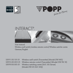
INTERACT3.
User manual
Wireless switch insert/dimmer insert/insert for sun blind
German/English
53912.00.101.01
53913.00.101.01
53914.00.101.01
Wireless switch insert (Actuator) (Model ZW ES 1000)
Wireless dimmer insert (Actuator) (Model ZW EDAN 300)
Wireless insert for sun blind (Actuator) (Model ZW ESJ)
1
INTERACT3.
Dear INTERACT3 user:
You can download this user manual in an appropriately larger
format from our internet website www.popp.eu.
Our service hotline is available for further product-relevant
questions at the service line: +49 (0) 92 73/73-150.
2
INTERACT3.
Index of contents/overview of chapters
1.
General information on “Z-Wave” ........................................5
2. General information ..................................................................8
2.1 LED indication..............................................................................8
3. Before installation/startup .......................................................9
4. Product description ................................................................ 11
5. Network inclusion .................................................................. 15
5.1 Adaptation ............................................................................... 15
5.2 Special adjustments .............................................................. 16
5.2.1 Adjustment of operation times of the window blind ..... 16
5.2.2 Stop-functionality ................................................................... 19
5.3 Synchronization of various devices....................................20
5.3.1 Set up of a 1-way connection .............................................24
5.3.2 Set up of a 2-way connection .............................................25
5.4 Deleting links ...........................................................................25
3
INTERACT3.
5.5 Association of devices without direct radio link
(assigned association) ............................................................27
5.6 Inclusion network devices into the network
of other manufactures ............................................................29
6. Use/handling ...........................................................................30
6.1 Special functions of radio-controlled dimmer .................. 31
6.2 Special function – child protection .................................... 31
7. Reset ...........................................................................................32
8. Electrical connection ..............................................................33
8.1 Switch – 3-way technology .................................................33
8.2 Dimmer – 2-way technology ...............................................33
8.3 Sun blind control .....................................................................35
8.4 Micro-fuse ..................................................................................36
9. Technical Data ..........................................................................38
10. Guarantee ................................................................................42
4
INTERACT3.
1. GENERAL INFORMATION ON “Z-WAVE”:
INTERACT³ is a radio system that is based on Z-WAVE technology. INTERACT³ off ers a varied range of advantages in
comparison to other radio systems:
Safe:
Generally radio systems build a direct link between the transmitter and the receiver. The radio signal is attenuated by every
obstacle along its path (in the household e.g. wall, furniture etc.),
in the worst case the radio system ceases to function. The advantage of the intelligent INTERACT³ system is the so-called routing
function: All devices of INTERACT³ not only act as transmitter
or receiver but also simultaneously as “repeater”. Should a direct
radio link between the transmitter or the receiver not be possible,
communication will be established with the assistance of other
devices.
5
INTERACT3.
6
INTERACT3.
Communicative:
INTERACT³ is a bidirectional radio system. This means that a
signal is not just sent but also a feedback confirming the reception of the signal occurs automatically. The safety of transmission
of the INTERACT³ radio-bus-technology is comparable with that
of a wire-linked bus system. It is likewise possible to determine
the switching status by pushing a button: Has the cellar light been
definitely switched off?
Established:
Although the Z-Wave technology is new, it has already developed to form a technical standard. Renowned manufacturers from
various fields offer solutions and applications that are based on
Z-Wave technology and compatible among one another. This
makes the system fit for the future and promises further upgrade
phases. Further information can be found on www.z-wave.
com.
Trouble-free:
INTERACT³ transmits at a regulated frequency band with a frequency of 868 MHz. Every INTERACT³ network has its own
unique network identification. Therefore, it is possible to operate
two or more independently-operating networks in a room or home
without any interferences. Troubles that can be caused by other
devices, as is the case in open, non-regulated frequencies (e. g.
433 MHz) are excluded.
Dynamic:
INTERACT³ is equipped with a dynamic network structure. Right
from the start, the position of the individual INTERACT³ device
who are supplied with 230 Volts is monitored and automatically
updated in the case of changes. As a means of which it is possible to continuously adapt the network to its individual requirements, wholly automatically without the necessity of any programming tasks.
7
INTERACT3.
2. GENERAL INORMATION:
3. BEFORE INSTALLATION/STARTUP:
2.1 COLOR CODES AT THE EQUIPMENTS:
Please read carefully the enclosed user manual before installation of the radio-actuator, in order to ensure an error-free functioning.
Red:
8
INTERACT3.
Device defective/
Configuration not successful.
Green:
Configuration successful.
Blinking green:
Configuration mode active.
Blinking red/green:
Device not programmed.
ATTENTION: Works with 230 voltage networks may be done
only by authorized technicians under consideration of the
country-specific installation guidelines/norms. Prior to the
assembly of the product, the voltage network has to be switched off and ensured against re-switching.
The product is permitted only for proper use as specified in the
user manual. Any kind of guarantee claim has to be forfeited if
changes, modifications or painting are undertaken. The product
must be checked for damages immediately after unpacking. In
the case of a damages, the product must not be operated in any
case.
9
INTERACT3.
If a danger-free operation of the equipment cannot be assured,
the voltage supply has to be immediately interrupted and the
equipment has to be protected from unintended operation.
NOTE: The actuators are dispatched in the delivery state
“not programmed”. While installation or actuating the pushbutton, this status is showed by a blinking red/ green LED.
INTERACT3.
4. PRODUCT DESCRIPTION:
Wireless switch insert: (Actuator switch)
(53912.00.101.01) (Model: ZW ES 1000)
Wireless dimmer insert: (Actuator dimmer)
(53913.00.101.01) (Model: ZW EDAN 300)
Wireless insert for sun blind: (Actuator Jalousie)
(53914.00.101.01) (Model ZW ESJ)
Support plate for the control
of the compensator
(can be clipped on)
Status LED
UP-button
DOWN-button
Safety
Terminal clamping
10
11
INTERACT3.
Switch/Dimmer: Serves for the switching or dimming of connected lights either via radio signals or directly over clipped-on
radio-rockers.
Sun blind control: The INTERACT³ wireless insert of sun blind is
for the wireless opening and closing of window blinds, shutters,
sun blinds and electronic gates. The wireless sun blind automatically turns off the contact after about 2 minutes (value set at delivery) in order to protect the motor.
The different flush-mounted inserts act as actuators.
INTERACT3.
Installation:
The build-in can be controlled both by using clipped-on rockers,
as well as wireless wall switch or remote control. The assembly
must take place in a voltage-free state by an authorized electrical technician. Turn off the power supply prior to the mounting
and confirm the absence of voltage with a 2-pin voltage checker.
Protect your installation from re-switching. An assembly in built-in
sockets is possible. As a result of the compact design, the wireless switch/ dimmer can be fastened to canopies (depth min. 30
mm), sun blinds and suspended ceilings, etc.. For facilitating this
purpose, the clipped-on switch or base plate may be removed.
NOTE: The use of flush-mounted insert with equipments that
do not comply with the technical standards can cause malfunctioning or damage connected equipments or fl ushmounted inserts.
12
13
INTERACT3.
Typical application:
With the help of a flush-mounted insert, an existing switch installation can be enhanced to a wireless-capable one. The existing
switch is replaced by the wireless insert including support ring
and the radio-rocker. It can also be manually switched as before,
however, it can also be alternatively remote-controlled by means
of a controller (remote control or wall switch).
INTERACT3.
5. FUNCTION/OPERATION:
5.1 NETWORK INCLUSION:
For the network inclusion of the wireless switch/dimmer, you need
a controller (remote control or wall switch).
Press 3 times
in each case
14
Press the “UP” or “DOWN” button on the desired group/scene
of the remote control or the wall switch three times (blinks green)
and then three times on the device to be included: The device is
automatically associated with the selected group/scene or wall
switch.
15
INTERACT3.
NOTE: If a radio link should not be possible while network
inclusion, please bring the controller closer to the radio insert.
NOTE: For the programming, both the controller as well as
the built-in actuator have to be supplied with power.
5.2 SPECIAL ADJUSTMENT
5.2.1 ADJUSTMENT OF THE OPERATING TIMES OF THE
SUN BLIND CONTROL:
If a wireless sun blind control is integrated for the first time into
an INTERACT³ network, it is recommended that an adjustment
of the operating times is undertaken, so that the window blind
control can be included in the scenarios without any difficulty.
Background information: A shutter/window blind does not necessarily have identical operating times in the UP and the
DOWN directions. The window blind control has to be adjusted
to this, so that a desired, preset value (e.g. window blind to 80%)
is attained both in the upward as well as downward motion.
16
INTERACT3.
For the adjustment of the operating times of the wireless sun blind please
follow the below instructions:
NOTE: Please note that you have to possibly remove the mounted rocker of the window blind for this programming step.
NOTE: The window blind must first be driven along the upward
direction up to the end stop. The reduction of the operating time
must be started from the upper maximum position, if not the
programmed values would be falsified.
“UP“ &
“DOWN“
... then ...
“UP“ or
“DOWN“
1. Move the window blind along the upward direction up to the end stop
2. Simultaneously press the “UP” and “DOWN” buttons of the radiocontrolled wireless window blind for 2 seconds, the LED blinks green.
3. Move the window blind with the “UP” or “DOWN” buttons of the
radio-controlled wireless window blind along the intended direction. During this measurement time, the LED promptly blinks green.
17
INTERACT3.
4. Release control in the target position. The window blind stops,
the LED of the control system confirms the successful folding with
a 3 second green light and a failed folding with a red light.
NOTE: The set values remain stored even after a power failure. The adjustment process of the operating times can be
repeated anytime.
NOTE: Should the adjustment of the operating times take place
with the help of the configuration tool of a third-party manufacturer, you can consider the following values as the basis:
Please note that the adjustments should be undertaken only by
well-versed technicians.
0x00
= no interruption/permanent operation
0x01-0x7F = 1 second to 127 seconds in 1-second steps
0x80-0xFE = 130 seconds (0x80) to 1390 seconds
(0xFE) in 10 second-steps
0xFF
= factory settings 120 seconds
18
INTERACT3.
5.2.2 ADJUSTING THE STOP-FUNCTIONALITY:
You can also programm the shutter actuator in a way, that in case
of a press in the apposite direction, the shutter won‘t stop, but
continue directly in the opposite way (Z-Wave conform). Please
proceed as follows:
• Hold the “UP” and “DOWN” button of the shutter actuator
simulaneausly for 5 seconds. Please note, that the devise
nust not be included in the network!
• Alternatively by configuration command (only for adviced
users): Set the configuration value “1” to the value “0” in order to disable the stop-functionality.
In order to onable the stop-functionality, please proceed as follows:
• Hold the “UP” and “DOWN” button of the shutter actuator
simulaneausly for 5 seconds. Please note, that the devise
nust not be included in the network!
• Alternatively by configuration command (only for adviced
users): Set the configuration value “1” to the value “1” in order
to enable the stop-functionality.
19
INTERACT3.
5.3 SYNCHRONOUS SWITCHING OF THE VARIOUS
DEVICES
INTERACT3.
Practical example:
While entering the living room all the lights turn on, however,
later on they can be individually dimmed as desired.
The different build-in offer the possibility to link up to 4 devices
among one another. Thus, several devices can be switched or
dimmed simultaneously. One differentiates between:
Actuator 1
One-way connection: A dimmer passes on a signal to
another (one predominates the other).
Actuator 2
By dimming of the first actuator, for instance, by 10 %, all other actuators are likewise dimmed by 10 %. However, each actuator can still
be manually adjusted.
20
Actuator 3 Actuator 4
REMARK: If the actuators at the radio remote control are divided into different groups, then the manual setting can also be
remotely controlled.
21
INTERACT3.
INTERACT3.
2-way connection: Both are equivalent, it can be controlled
by both one of them as well as the other.
Actuator 1
In contrast to the 1-way connection, an additional feedback
connection is programmed. Thus, all the 4 actuators can be operated irrespective of which one of the 4 actuators. An individual
switching is not possible in the above-illustrated example.
22
Actuator 2 Actuator 3
Actuator 4
Practical example:
In the case of spacious rooms such as offi ce spaces, in which
diff erent lighting regions are allocated to diff erent outer cables.
23
INTERACT3.
INTERACT3.
5.3.1 SETTING UP A ONE-WAY LINK:
TARGET
ACTUATOR
... then ...
“ASSOC.“
1.
2.
3.
4.
... then ...
“INCL.“
SOURCE
ACTUATOR
... then ...
Triple-press “UP“
or “DOWN“
Triple-press “UP“
or “DOWN“
Press the “ASSOC.” button on the controller for two seconds.
Subsequently press the “INCL.” button on the controller.
Target actuator: Triple-press the “UP” or “DOWN” button
on the actuator to be enabled within a span of 1.5 seconds.
Source actuator: Triple-press the “UP” or “DOWN” button
on the actuator to be enabled within a span of 1.5 seconds.
The successful link is signaled by a green light, whereas a failure
is indicated by a red light.
24
5.3.2 SETTING UP A 2-WAY LINK:
For the formation of a 2-way link or to be able to reciprocally
switch the equipments, the programming step of point 5.3.1 has
to be repeated, whereby this time the source and the target
equipments have to be swapped.
5.4. DELETING OF LINKS:
For deletion of links, the link has to be deleted in the case of the
respective source device i.e. in a 2-way link, we have to deal
with 2 source devices, whereby the respective link has to be
deleted.
TARGET
ACTUATOR
... then ...
“ASSOC.“
... then ...
“EXCL.“
SOURCE
ACTUATOR
... then ...
Triple-Press
“UP“ or
“DOWN“
Triple-Press
“UP“ or
“DOWN“
25
INTERACT3.
1.
2.
3.
4.
Press the “ASSOC.” button on the controller for two
seconds.
Subsequently press the “EXCL.” button on the controller.
Triple-press the “UP” or “DOWN” button on the target
actuator within a span of 1.5 seconds.
Triple-press the “UP” or “DOWN” button on the source
actuator thrice within a span of 1.5 seconds.
NOTE: If a link with a wireless wall transmitter has to be deleted, the same has to be present in the direct radio-range of
the receiver.
INTERACT3.
5.5 ASSOCIATION OF DEVICES WITHOUT DIRECT RADIO
LINK (“ASSIGNED ASSOCIATION”):
In some cases, it can happen that the wireless wall switch to be associated is already mounted, but has no direct radio-communication
with the receiver. Thanks to the routing function, a direct radio-communication is not direly needed anymore for switching as the signals
can be forwarded over further devices. In order to associate the
wireless wall transmitter in such a case, you must seek the help of
another controller, with the help of which you can adapt the “out of
range” wall transmitter.
Please take note of the following instructions:
TARGET
ACTUATOR
... then ...
“ASSOC.“
26
... then ...
“INCL.“
SOURCE
ACTUATOR
... then ...
Triple-press “UP“
or “DOWN“
Triple-press “UP“
or “DOWN“
27
INTERACT3.
1.
2.
3.
4.
5.
6.
Go to the desired target actuator with the help of a controller of your choice.
Press the “ASSOC.” button on the controller for 2 seconds.
Short-press the “INCL.” button on the controller.
Triple-press the “UP” or “DOWN” button or the “FUNCTION” button on the target actuator within a span of 1.5
seconds.
Go with the controller in your hand towards the wireless
wall transmitter to be adapted.
Triple-press on the “UP” or “DOWN” button on the wireless wall transmitter within a span of 1.5 seconds.
The successful association is signaled by a green light whereas
a failure is signaled by a red light.
28
INTERACT3.
5.6 INCLUSION OF THE ACTUATOR INTO NETWORK OF
OTHERS MANUFACTURES:
Controller
Third-party
manufacturer
...then...
...then...
Triple-press “UP”
or “DOWN”
Start the inclusion step on the concerned controller of its network and
triple-press the “FUNCTION” button of the equipment to be included
within a span of 1.5 seconds..
Triple-press
NOTE: For information on handling or starting the inclusion step
of products of other manufacturers, please read the documents
of the respective manufacturer.
29
INTERACT3.
6. USE/HANDLING:
The build-in actuator can be operated either over a controller
(remote control or wall switch) or directly by means of a clippedon rocker.
Wireless switch insert: switched on/off by a short press.
Wireless dimmer insert: in the case of dimmer, there is the
additional possibility of dimming UP/DOWN by a longpress of the rocker.
Wireless insert for sun blind: moved UP/DOWN by a short
push. The movement can be stopped by a short pressing in the
opposite direction. A long-press or holding of UP/DOWN directs to the corresponding direction, as long as the rocker is
held.
30
INTERACT3.
6.1 SPECIAL FUNCTIONS OF WIRELESS DIMMER INSERT:
The wireless dimmer insert saves the most recently-set light intensity and automatically switches back to the same level of brightness at which it was switched off..
6.2 SPECIAL FUNCTIONS – CHILD PROTECTION:
If the radio plug adaptor is present in the “child protection mode”
(also see the user manual wireless wall switch or remote control),
this can be disabled by triple-pressing the “FUNCTION” button
within a span of 1.5 seconds. After 5 seconds of inactivity, the
tamper-proof “child protection mode” is automatically reactivated.
KINDLY NOTE: The description for activation or deactivation of the child protection function is described in the user
manual of the remote control/wall switch!
31
INTERACT3.
7. RESET:
8. ELECTRICAL LEADS:
Ausschaltung
Sometimes it might be necessary to reset the device to the factory settings and delete all the programming steps or associations. For resetting, a controller (remote control or wall switch) is
needed.
8.1 SWITCH WITH 3-WAY TECHNOLOGY:
Switching off
L
N
... then ...
“EXCL.”
1.
2.
Triple-press “UP”
or “DOWN”
L = lead-in AC 230V/50 Hz
N = neutral line
= switched line
Press the “EXCL.” button on the controller for 2 seconds,
the LED blinks green.
Triple-press the “UP” or “DOWN” button on the peer to be
reset to the factory settings within a span of 1.5 seconds.
The successful reset operation is signaled by a green light, whereas a failure by red light.
32
Motorsteuerung andere Spannung
g
240 V~
INTERACT3.
NOTE: neutral line is indispensible for the functioning of the
receiver!
Motorsteuerung andere Spannung
Impulsschalter
33
Ausschaltung
L
L
N
N
INTERACT3.
INTERACT3.
L
N
8.2 SWITCH WITH 2-WAY TECHNOLOGY:
8.3 SUN BLIND CONTROL:
Switching off
L
N
COM c
1 (OUT)
2 (OUT)
L (IN)
N (IN)
PE
L
N
=
=
=
=
=
=
=
=
brown or black
blue
switch line-in (voltage-free)
switch contact (line-out)
switch contact (line-out)
brown or black (voltage supply)
neutral line blue (voltage supply)
protection line green/yellow
Motorsteuerung
Motorsteuerung andereMotorsteuerung
Spannung andere Spannung
Impulsschalter
Motorsteuerung andereImpulsschalter
Spannung
Motorsteuerung 220-240
V~
Motorsteuerung
andere Spannung
Motorsteuerung 220-240 V~
Motor control 220 - 240 V
L
N
L
L
N
N
Impulsschalter
Motorsteuerung andere Spannung
Motorsteuerung 220-240 V~
˜
L
N
Motor control other voltages Motor control other voltages
Pulse switch
L
L
N
N
L
L
L
N
N
N
PE
PE
PE
M
L
= lead-in
AC 230 V/50 Hz
N = neutral line
= switched line
M
M
34
M
Motorspannung
dere Spannung
M
M
M
Motorspannung
voltage
M Motor
Motorspannung
35
INTERACT3.
8.4 MICRO-FUSE:
Wireless dimmer insert (53913.00.101.01) T 1,25 A H
(Load 1.25 Ampere, high shutdown capacity) D: 5 mm, L: 20 mm
Wireless switch insert (53912.00.101.01) T 10 A H
(Load 10 Ampere, high shutdown capacity) D: 5 mm, L: 20 mm
Wireless insert for sun blind (53914.00.101.01) T 8,0 A H
(Load 8.0 Ampere, high shutdown capacity) D: 5 mm, L: 20 mm
36
INTERACT3.
NOTE: The micro-fuse deals with a backup for the equipment
that is specifically designed to this radio-controlled wireless
dimmer/ switch. Please use only this fuse type. This microfuse should protect this radio-controlled wireless dimmer/
switch from overload and short circuits. When using another
fuse component there is a danger that the device can be
destroyed. A spare fuse is provided in the fuse holder.
TROUBLE NOTES: All devices of the system have to be included, therefore, all the articles of the INTERACT³ radio system can be combined. The transmission or reception range
is up to 100 m in free field and is dependent on the onsite
prevailing conditions.
37
INTERACT3.
INTERACT3.
9. TECHNICAL DATA:
Wireless dimmer insert (model ZW EDAN 300)
Wireless switch insert (model ZW ES 1000)
Receiving frequency:
868.42 MHz
Receiving frequency:
868.42 MHz
Switching capacity:
bulbs
HV-, NV-Halogen-, incandescent
Switching capacity:
2,300 W, 460 VA, 600 W,
incandescent bulbs
Operating voltage:
230 V, 50 Hz
25 – 300 W, 40 – 300 VA
Operating voltage:
230 V, 50 Hz
Micro-fuse:
T 1,25 A H
Micro-fuse:
T 10 A H
Dimensions (H x W x D): 52 x 52 x 31 mm (without cover)
71 x 71 x 42 mm (with cover)
Dimensions
(H x W x D):
52 x 52 x 31 mm (withour cover)
71 x 71 x 42 mm (with cover)
Operating temperature: 0°C to +40°C
Operating temperature: 0°C to +40°C
38
39
INTERACT3.
INTERACT3.
Wireless insert of sun blind (model ZW ESJ)
Receiving frequency:
868.42 MHz
Switching capacity:
ohmic 1,800 W
460 VA (motors + luminescent lamps)
500 W incandescent bulbs
Operating voltage:
230 V, 50 Hz
Switching time:
2 minutes (time period is factory set)
Micro-fuse:
T8AH
WRONG APPLICATIONS: Do not operate any equipments
that could cause damages while inadvertently turning on
(e.g. disk saw). Operate only equipments that are approved
for operating at 230 V/ 50 Hz. Do not use radio-controlled
wireless dimmer/ switch in security areas (e.g. as emergency switch or alarm). Load the wireless dimmer/switch only
up to the specified maximum load.
Dimensions (H x W x D): 52 x 52 x 31 mm (without cover)
71 x 71 x 42 mm (with cover)
Operating temperature: 0°C to +40°C
All the above-mentioned products comply with the norms only
in indoor use: RTTE 1999/05/EG, EN 60669.
40
41
INTERACT3.
10. GUARANTEE:
The products of the INTERACT³- series are fabricated by means
of modern technology and are subjected to strict quality controls.
Should defects still occur in your equipments, the POPP GmbH
offers guarantee to the following extent.
1. Our guarantee offer comprises the repair or new delivery of
an equipment, if it exhibits a defect in the function or material
composition that can be proven.
2. The guarantee offer is not based upon the natural wear and
tear or transport damages or damages as a consequence of
not paying attention to the installation instructions as well as
improper installation. One automatically loses the claim to
the guarantee offer, if the equipment has been disassembled
after diagnosis of errors.
3. The guarantee term amounts to 24 months from the date of
purchase by the end-user.
42
INTERACT3.
The compliance of the claim period has to be proved by a statement of the purchase date by means of enclosed invoice, delivery note or similar documents.
Batteries, LEDs and rechargeable batteries that are sent along
with the delivery are not covered by the guarantee offer.
The POPP GmbH does not accept claims due to indirect, consequential and property damages.
If defects are observed in the equipment, please send the equipment with enclosed description of the defect to the following
address:
POPP GmbH
Kulmbacher Straße 27
95460 Bad Berneck
53912.14.02
Juli 2008
43
INTERACT3.
INTERACT3.
Disassociate
Press the “ASSOC.” button of the
controller for 2 seconds, subsequently
the “DOWN” button, followed by the
“send Node Info Frame” of the target
equipment.
Start Exclude mode Press “EXCL.” button of the controller for
2 seconds.
Learn Mode
Triple-press “UP” or “DOWN”
button.
Associate
Send Node Info Frame – (Slave) triple-press “UP” or
“DOWN” button
– (Controller) press “INCL.”
for two seconds.
REMARK: Note for well-versed users. All-manufacturer ZWave-compatible programming functions:
Start Include mode
Triple-press “INCL.” button of the
controller.
Press “ASSOC.” button of the controller
for 2 seconds,subsequently press the
“UP” button on the controller followed
by the “send Node Info Frame” of the
target equipment.
Re-include/Replicate Triple-press the “INCL.” button of the
controller followed by the “send Node
Info Frame” of the target equipment.
44
Add node
Triple-press “UP” or “DOWN” button
(inclusion or primary controller).
45
Please visit our website www.popp.eu in the internet and get to
know about further innovative products of the POPP GmbH, such
as e. g. the professional power outlet strip adaptus® INTERACT³
with integrated Z-Wave radio technology.
POPP GmbH
Kulmbacher Straße 27
D-95460 Bad Berneck
www.popp.eu
46