1
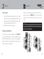
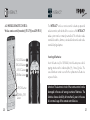
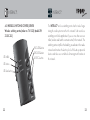
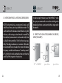
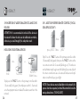
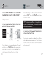
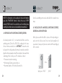
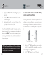
INTERACT3.
User manual
Wireless wall switch/wireless remote control/Wireless switchin centre
German/English
53911.00.101.01 Wireless wall switch (Transmitter) (Model ZW WS)
53915.00.001.01 Wireless remote control (Transmitter) (Model ZW FB 10)
53919.00.001.01 Wireless switching centre (SUC SIS Server)
(Model ZW ZS SUC SIS))
1
INTERACT3.
Dear INTERACT3 user:
You can download this user manual in an appropriately larger
format from our internet website www.popp.eu.
Our service hotline is available for further product-relevant
questions at the service line: +49 (0) 92 73/73-150.
2
INTERACT3.
Index of contents/overview of chapters:
1.
2.
2.1
2.2
2.3
3.
4.
4.1
4.2
4.3
5.
5.1
General information on the “Z-Wave” ..................................6
General information ..................................................................9
LED indication .............................................................................9
Interoperability different devices ........................................10
Improvement of the network quality .................................. 11
Before installation/startup ..................................................... 11
Product description ................................................................. 14
Wireless wall switch ............................................................... 14
Wireless remote control ........................................................20
Wireless switching centre/server .......................................22
Networks without server .......................................................24
Direct inclusion of devices to a group/scene...................25
3
INTERACT3.
5.2 Switching and dimming ..........................................................26
5.3 Status enquiry ...........................................................................27
5.4 Association of devices without direct radio link .................28
5.5 Deleting devices from group/scene ...................................... 30
5.6 Deleting a complete group/scene ...................................... 31
5.7 Removing devices ...................................................................32
5.8 Resetting controller ..................................................................33
5.9. Insertion of additional devices and controllers ..............34
5.9.1 Adding further remote control...............................................35
5.9.2 Associating the network devices with a new or existing
remote control ..........................................................................36
5.10 Inclusion INTERACT³ products into networks of
other manufacturers ...................................................................36
4
INTERACT3.
5.11 Inclusion the products other manufacturers into
an INTERACT³ network ........................................................37
6. Networks with switching centre/server .............................38
6.1 Including a controller into a new network.........................39
6.2 Including a controller into an existing network....................41
7. Special functions – Special applications..........................43
7.1 “Child protection function” –
tamper-proof programming ...................................................43
7.2 “All ON/ All OFF” function ...................................................45
7.3 Synchronization of various devices.....................................48
7.4 Including and operating of battery-operated equipments 52
8. Usage/handling .....................................................................58
9. Technical Data .............................................................................60
10. Guarantee ..................................................................................... 61
5
INTERACT3.
1. GENERAL INFORMATION ON “Z-WAVE”:
INTERACT³ is a radio system that is based on Z-WAVE technology. INTERACT³ offers a varied range of advantages in
comparison to other radio systems:
Safe:
Generally radio systems build a direct link between the transmitter and the receiver. The radio signal is attenuated by every
obstacle along its path (in the household e. g. wall, furniture
etc.), in the worst case the radio-bus-system ceases to function.
The advantage of the intelligent INTERACT³ system is the socalled routing function: All devices of INTERACT³ not only act
as transmitter or receiver but also simultaneously as “repeater”.
Should a direct radio link between the transmitter or the receiver not be possible, communication will be established with the
assistance of other devices.
6
INTERACT3.
Communicative:
INTERACT³ is a bidirectional radio system. This means that a
signal is not just sent but also a feedback confirming the reception of the signal occurs automatically. The safety of transmission
of the INTERACT³ radio-bus technology is comparable with that
of a wire-linked bus system. It is likewise possible to determine
the switching status by pushing a button: Has the cellar light been
definitely switched off?
Trouble-free:
INTERACT³ transmits at a regulated frequency band with a frequency of 868 MHz. Every INTERACT³ network has its own
unique network identification. Therefore, it is possible to operate
two or more independently-operating networks in a room or home
without any interferences. Troubles that can be caused by other
devices, as is the case in open, non-regulated frequencies (e. g.
433 MHz) are excluded.
7
INTERACT3.
Established:
Although the Z-Wave technology is new, it has already developed to form a technical standard. Renowned manufacturers from
various fields offer solutions and applications that are based on
Z-Wave technology and compatible among one another. This
makes the system fit for the future and promises further upgrade
phases. Further information can be found in www.z-wave.
com.
Dynamic:
INTERACT³ is equipped with a dynamic network structure. Right
from the start, the position of the individual INTERACT³ devices
who are supplied with 230 Volts is monitored and automatically
updated in the case of changes. As a means of which it is possible to continuously adapt the network to its individual requirements, wholly automatically without the necessity of any programming tasks.
8
INTERACT3.
2. GENERAL INORMATION:
2.1 COLOR CODES AT THE EQUIPMENTS:
Yellow:
Blue:
Red:
Device/group/scene is switched on.
Device/group/scene is switched off.
Device/group/scene defective/
Configuration not successful/Out of range.
Blinking yellow: Diming up.
Blinking blue:
Diming down.
Green:
Configuration successful.
Blinking green:
Configuration mode active.
Blinking Red:
Child protection active.
Red/green:
Device not programmed.
Red/yellow/green: Resetting.
9
INTERACT3.
NOTE: Combinations are possible within a group. For
instance, an equipment is “failed”, and an equipment is switched off.
2.2 INTEROPERABILITY OF DEVICES DIFFERENT
MANUFACTURERS:
It is possible to integrate devices of different manufacturers and
from various functional groups such as light, multimedia, heating
and air-conditioning. Communication and interoperability of the
different devices is ensured by a common “Speaks Z-Wave”
certification. Please contact the different manufacturer for questions on the presence and nature of interlinked restrictions during
the use of the individual equipments.
10
INTERACT3.
2.3 IMPROVEMENT OF THE NETWORK QUALITY:
In general, every electrically-operated devices serves as an
amplifier for the incoming signals. These are forwarded to the
adjacent device, as a result of which the maximum range of a
communication can be increased. The more devices are present
in a network, the denser the network and higher is the quality of
signal transmission.
3. BEFORE INSTALLATION/ STARTUP:
Please read carefully the enclosed user manual before installation, to ensure an error-free functioning.
11
INTERACT3.
ATTENTION: Works with 230 voltage networks may be
done only by authorized technicians under consideration
of the country-specific installation guidelines/ norms. Prior
to the assembly of the product, the voltage network has to
be switched off and ensured against re-switching.
INTERACT3.
NOTE: The product is dispatched in the delivery state “not
programmed”. While installation or actuating the pushbutton, this status is showed by a blinking red/green LED.
The product is permitted only for proper use as specified in the
user manual. Any kind of guarantee claim has to be forfeited if
changes, modifications or painting are undertaken. The product
must be checked for damages immediately after unpacking. In
the case of a damage, the product must not be operated in any
case.
If a danger-free operation of the equipment cannot be assured,
the voltage supply has to be immediately interrupted and the
equipment has to be protected from unintended operation.
12
13
INTERACT3.
INTERACT3.
4. PRODUCT DESCRIPTION:
4.1 WIRELESS WALL SWITCH:
Wireless wall switch (Transmitter) (761 231) (Model ZW WS)
UP-button
INCLUDE-button
EXCLUDE-button
ASSOC-button
DOWN-button
14
The INTERACT³ wireless wall switch is a battery-operated radiotransmitter, with which all the actuators of the INTERACT³ radiobus-system can be remotely controlled. This includes radiocontrolled switches, dimmers, window blind controls and
radio-controlled plug adaptors.
In simple terms, the INTERACT³ wireless wall switch is a radio
remote control, with which only a single group can be actuated.
The radio-bus-system can be completely enhanced according
to the needs in any possible manner. Any number of radio-controlled wall-mounted switches can be installed, so that even a
more complex 3-way, 2-way or synchronized dimmer arrangements can be realized without considerable difficulty. You can
choose your individual design from the series of switches that
are designated to the INTERACT³ radio-bus-system.
15
INTERACT3.
INTERACT3.
Insertion of batteries:
Click into – a multiple frame as a combination.
Insert both the batteries (2 x LR8D425) into the battery case while paying attention to the indicated plus (+) / minus (-) poles. The
wireless wall switch can now be mounted.
Attention: The electronic circuit of the wall-mounted switch
can be damaged in the case of wrong insertion of batteries.
Stick-on process:
Integration/mounting:
Thanks to the extremely flat design of the INTERACT³ wireless
wall switch, it does not require any substructure and therefore
offers a variety of mounting options on various backgrounds:
Stick on – to smooth surfaces such as glass and tiles with the
help of an adhesive strip.
Screw on – to walls or built-in sockets (switches and hollow wall
sockets).
16
1.
2.
3.
4.
Clean up the mounting surface so that it is dust and
grease-free.
Attach the adhesive strips on to the rear side of the wall
switch.
Stick the wall switch with the upwardly-pointing arrow
(“TOP”) to the mounting surface that is selected by you.
Align the wireless wall switch with only one edge of the
base plate at a plane surface (e. g. spirit level, ruler) and
press it against the mounting surface.
Mount the frame and the rocker.
17
INTERACT3.
Screw-on process:
1.
2.
Fasten the plastic support ring with screws on to a socket
to be built-in or with screws and pegs directly to the wall.
Please pay attention to the fact that the mounting is done
with the upwardly-pointing arrow (“TOP”).
Mount the frame and the compensator.
INTERACT3.
Replace the existing single frame by a double frame with a suitable design, mount an INTERACT³ wireless wall switch and
click the free frame section and the rocker into the wireless wall
switch.
NOTE: Please pay attention to the fact that existing support
rings and base plates flush-fi t with one another in the case
of multi-socket combinations.
Clicking into a multiple frame:
You can enhance an existing installation with an INTERACT³
wireless wall switch without the need for the installation of additional fl ush-mounted sockets. You only need an appropriate
multiple frame with a suitable design for the existing series of
switches and a wireless wall switch.
18
19
INTERACT3.
INTERACT3.
4.2 WIRELESS REMOTE CONTROL:
Wireless remote control (transmitter) (761 279) (model ZW FB 10)
INCLUDE-button
EXCLUDE-button
ASSOC-button
LOW-Batt.-button
UP-/ON-button
DOWN-/OFFbutton
20
Inserting of batteries:
1
2
3
4
The INTERACT³ wireless remote control is a battery-operated
radio-transmitter, with which all the receivers of the INTERACT³
radio system can be remotely controlled. This includes radiocontrolled switches, dimmers, window blind controls and radiocontrolled plug adaptors.
1
2
3
4
Insert the batteries (4 x 1.5V AAA) into the battery case while
paying attention to the indicated plus (+) / minus (-) poles. The
saved functions remain even after the replacement of batteries
or power failure.
Attention: The electronic circuit of the remote control can be
damaged in the case of wrong insertion of batteries. The
batteries have a durability of more than 2 years in the case
of a normal usage of the remote control device.
21
INTERACT3.
INTERACT3.
4.3 WIRELESS SWITCHING CENTRE/SERVER:
Wireless switching centre (order no. 761 323) (model ZW
ZS SUC-SIS)
LED-traffic
INCLUDE-button
EXCLUDE-button
ASSOC.-button
The INTERACT³ wireless switching centre has the task of organizing the radio system or rather the network. Such a wireless
switching centre finds application if you use more than one controller (wireless wall switch or remote control) in the network. The
switching centre simplifies the handling, coordinates in the radionetwork and monitors the battery level of the battery-operated
devices and takes over a multitude of management functions in
the network.
LED-status
LED-low battery
22
23
INTERACT3.
5. 0 NETWORK WITHOUT A SWITCHING CENTRE/SERVER:
NOTE: Each controller (e.g. remote control, wireless wall
switch) has a factory-set unique identification number. This
is attributed to further devices and controllers during their
inclusion, so that a unique, closed network is created. The
first controller (remote control or wireless wall switch) is the
so-called “primary controller”, which has the unique capability of including new device etc. in a network. Each additional controller that is included in this network falls below
this primary controller and becomes a “secondary controller”, with which it can be switched but does not allow the
possibility of the integration of new devices.
INTERACT3.
In order to simplify the daily use of the INTERACT³ radiobus-system, we recommend to use a wireless switching centre
immediately after the second controller that is integrated in
the network.
5.1. DIRECT INCLUSION OF EQUIPMENTS IN GROUP/
SCENE (“INCLUDE”):
...then...
“UP“ or “DOWN”
24
...or...
press 3 times
press 3 times
25
INTERACT3.
Press 3x on “UP” or “DOWN” on the desired group/ scene of
the remote control or the wireless wall switch (blinks green) and
then press 3x on the devices. The device is automatically associated with the selected group/ scene or the wireless wall
switch.
INTERACT3.
5.3. STATUS ENQUIRY:
Press the “STATUS” button of the group to find out the status of
all the equipments in the group.
5.2. SWITCHING AND DIMMING:
Short-press the “UP” button to turn on or long-press to dim up
the group.
Short-press the “DOWN” button to turn off or long-press to
dim down the group.
26
Remark: This option is not possible with the wireless wall switch
(761 231).
27
INTERACT3.
INTERACT3.
5.4 ASSOCIATION OF DEVICES WITHOUT DIRECT RADIO
LINK (“ASSIGNED ASSOCIATION”):
...then...
“ASSOC.”
...then...
“INCL.”
...then
at the
target
WS
...or...
Press
3 times
Press
3 times
Press
3 times
In some cases, it can happen that the wireless wall switch to be
associated is already mounted, but has no direct radio-communication with the receiver.
Thanks to the routing function, a direct radio-communication is
not direly needed anymore for switching as the signals can be
forwarded over further devices. In order to adapt the wireless
wall transmitter in such a case, you must seek the help of another
controller, with the help of which you can adapt the “out of range” wall transmitter.
28
Please pay attention to the following instructions:
1.
Go to the desired target actuator with the help of a controller
of your choice.
2. Press the “ASSOC.” button on the controller for
2 seconds.
3. Short press the “INCL.” button on the controller briefl y.
4. Triple-press the “UP” or “DOWN” button or the
“FUNCTION” button on the target actuator within a
span of 1.5 seconds.
5. Go with the controller in your hand towards the wireless
wall transmitter to be adapted.
6. Triple-press the “UP” or “DOWN” button on the wireless
wall transmitter within 1.5 seconds.
The successful association is signaled by a green light whereas
a failure is signaled by a red light.
29
INTERACT3.
INTERACT3.
5.5 DELETING DEVICES FROM GROUP/SCENE (DEVICE
REMAINS IN THE NETWORK) (“DISASSOCIATION”):
5.6 DELETING A COMPLETE GROUP/ SCENE (DEVICES
REMAIN IN THE NETWORK) (“DISASSOCIATION”):
...then...
“ASSOC.“
...then...
“DOWN“
Press 3 times
...or...
NOTE: In the above-described deletion of equipments from a group/
scene, only the association with the corresponding group/ scene on the
controller (radio remote control/wireless wall transmitter) is deleted, the
equipment retains a network ID and remains in the network and can be
further associated as a router or with another controller.
30
...then...
Press 3 times
Press the “ASSOC.” button for 2 seconds, on the radio remote control (promptly blinks green), then the “DOWN” button on the group/ scene (slowly blinks
green), then triple-press the “UP” or “DOWN” button or the “FUNCTION”
button of the target equipment within 1.5 seconds.
„ASSOC.“
„DOWN“
Press for 10 seconds on the “ASSOC.” button on the remote
control until red/yellow/green is signaled. Then press the
“DOWN” button of the group/scene.
31
INTERACT3.
INTERACT3.
5.7 REMOVING DEVICES (RESET + REMOVE EQUIPMENT FROM NETWORK) (“EXCLUDE”):
...then...
...or...
Press “UP“ or
Press 3 times
“EXCL.”
“DOWN“ 3 times
Press the “EXCL.” button on the remote control for two seconds
(blinks green) and then triple-press the “UP” or “DOWN” button
or the “FUNCTION” button of the target equipment within 1.5 seconds.
NOTE: In the above-described deletion of devices, the device is removed from the network. It does not have a network
ID anymore and can also be included in a new network.
Moreover, the network is not available anymore as a router
in the existing network.
32
5.8 RESETTING CONTROLLER (RESET + REMOVE DEVICE
FROM NETWORK) (“EXCLUDE”):
...then...
“EXCL.“
...or...
Press 3 times
Press “UP“ or
“DOWN“ 3 times
Press the “EXCL.” button for fi ve seconds (red/yellow/green
blink), then press 3 times on the “ALL ON” button (prompt blinking) and 3 times on the “ALL OFF” button. (remote control) ir
3x “UP“ or 3x “DOWN“ (wall switch).
33
INTERACT3.
INTERACT3.
5.9 INSERTION OF ADDITIONAL DEVICES AND CONTROLLERS:
ATTENTION: It is recommended to include all the devices in
the network before the inclusion of additional controllers,
otherwise you would magnify the adaptation work.
INCLUSION OF ADDITIONAL DEVICES:
...then...
“INCL.“
...then...
press „INCL.“ 3 times
...or...
Press 3 times
5.9.1 ADDITION FURTHER REMOTE CONTROL (“INCLUDE & REPLICATION”):
Press “UP“ or
“DOWN“ 3 times
Triple-press the “INCL.” button on the primary controller within
1.5 seconds (blinks green), then triple-press within 1.5 seconds
on to the equipment to be included. The devices are then in the
network.
34
„INCL.“
Triple-Press the “INCL.” button of the primary controller within
1.5 seconds (blinks green), then press the “INCL.” button on the
new remote control for 2 seconds (blinks green). The inclusion
and replication cycle begins and the blinking frequency of both
the remote controls increases. A successful inclusion and replication is confirmed by a green light.
NOTE: If new devices are included later in the network, this
process has to be repeated, so that all the controllers have the
most-updated status. (“RE-INCLUDE”).
35
INTERACT3.
INTERACT3.
5.9.2 ASSOCIATING THE NETWORK DEVICES WITH A NEW
OR ALREADY EXISTING REMOTE CONTROL (“INCLUDE”):
Start the inclusion step on the concerned controller of its network
and press the “INCL.” button on the INTERACT³ controller to be
included for 2 seconds.
Similarly see point 5.1
5.10 INCLUSION OF INTERACT3 PRODUCTS INTO NETWORKS OF OTHER MANUFACTURERS
Controller
Third-party
manufacturer
...then...
Press 3 times
NOTE: For information on handling or starting the inclusion step
of products of other manufacturers, please read the documents
of the respective manufacturer.
5.11 INCLUSION OF OTHER MANUFACTURERS PRODUCTS
INTO AN INTERACT³ NETWORK:
...or...
press “UP” or “DOWN”
thrice
Start the inclusion step on the concerned controller of its network
and triple-press the “FUNCTION” button of the equipment to be
included within 1.5 seconds. The inclusion of an INTERACT³ controller into an external network follows the same logic.
36
Start the inclusion step as described above (cf. point 5) at the
wireless wall transmitter or the remote control. Send the inclusion
data of the device to be included to the wall-mounted transmitter
or the remote control.
37
INTERACT3.
NOTE: For information on the sending of inclusion information
(press the “FUNCTION” button 3 times in the case of POPP
actuators/“INCL.” button for 2 seconds in the case of controllers), please
read the product data sheets enclosed added by the manufacturer.
6. NETWORKS WITH SWITCHING CENTRE/SERVER:
As already stated in 4.3, it is recommended that a wireless
switching centre (Order No. 761 323) is employed in the case
of more than two controllers in an INTERACT³ network in order
to bypass the configuration of primary/secondary controller.
Apart from the equivalence of all the controllers, there are further
advantages that result by use of the radio base station:
• Permanent network monitoring
• Monitoring of battery-operated peers
• Automatic update of the included controllers
INTERACT3.
A wireless switching centre can be included in the network in two
ways:
6.1 INCLUSION OF A WIRELESS SWITCHING CENTRE/
SERVER IN A NEW NETWORK:
At first, please confirm that all the devices of the impending network exist in the delivery state, if not, it can lead to problems of
association. Subsequently it can be started with the building-up
of the network:
...then...
triple-press “INCL.”
38
„INCL.“
39
INTERACT3.
1.
2.
3.
Triple-press the “INCL.” button at the switching centre/server
within 1.5 s.
Press the “INCL.” button of the controller for 2 seconds.
The LED blinks green.
Both to products confi rm a successful inclusion with a
green light or a failure with a red light.
Repeat the step with a further controller that has to be accommodated in the network. You can now equivalently include additional
devices to the INTERACT³ remote control or associate with groups
or scenes by means of each included controller as described in
the preceding points.
INTERACT3.
6.2 INCLUSION OF A WIRELESS SWITCHING CENTRE/
SERVER IN AN EXISTING NETWORK:
An existing network can be enhanced at any time with a new
switching centre. As the switching centre assumes a numerous control and management functions in the network as described above,
we recommend you to use the switching centre as early as possible.
...then...
Press “INCL.” 3 times
NOTE: Should a network already exist, this can also be completely deleted or reset in order to include the wireless
switching centre in a new network.
40
“INCL.”
Triple-press the “INCL.” button of your primary controller
3 within 1.5 seconds, the LED starts to blink green and signals the change in the configuration mode.
2. Press the “INCL.” button at the server for 2 seconds.
41
1.
INTERACT3.
3.
INTERACT3.
Both the products confirm a successful inclusion step with
a green light or a failure with red light.
4.
5.
NOTE: For a trouble-free network functioning, the switching
centre now needs information on all controllers that come
into use in this network. For this purpose, you must register
each controller to the switching centre and provide access
to it with the necessary information. Please follow the below
instructions:
6.
7.
Triple-press the “INCL.” button of the server within 1.5
seconds, the LED begins to blink green.
Press the “INCL.” button of the controller to be included
for 2 seconds.
Both the products confirm a successful inclusion with a
green light or a failure with red light.
SPECIAL FUNCTIONS – SPECIAL APPLICATIONS:
7.1 “CHILD PROTECTION FUNCTION” – TAMPER-PROOF
PROGRAMMING:
...then...
Press “INCL.” 3 times
42
...or...
“INCL.”
“INCL.”
The INTERACT³ system can be optionally transformed to a
tamper-proof state. In this case, the devices can be operated
only after a manual disabling of the tamper-proof mode by
triple-pressing the function-button (“Sequence protection”) or
radio-controlled only in the “only radio mode”.
43
INTERACT3.
INTERACT3.
In the sequence mode after 5 seconds without activity, the device automatically resets back to the tamper-proof mode.
This function is of immense practical importance, since it can
prevent the non-authorized or accidental use of various devices
to a certain extent.
For the programming of such a “child-proof function”, please
pay attention to the following instructions:
2.
3.
...then...
“INCL:” &
“ASSOC.”
1.
44
...then...
thrice
...or...
press “UP” or
“DOWN”
3 times
Press the “INCL.” & “ASSOC.” buttons on the main remote control for two seconds. (blinks green).
Choose the desired protection mode now:
– e. g. group 1 “UP” → normal operation without tamperproof/child protection.
– e. g. group 1 “STATUS” → in order to activate the mode
“sequence protection”
– e. g. group 1 “DOWN” → in order to activate the “only
radio mode”.
Triple-press the “FUNCTION” button in the case of the
device to be protected within 1.5 seconds. The device thereby retains the previous switching status. Repeat the abovementioned steps for each device to be processed.
7.2 „All ON/All OFF“ FUNCTION:
INTERACT³ offers the possibility to use “All ON/ All OFF” function. You can simultaneously switch the devices that are organized
in various groups and scenes. Typical applications, for instance, the
possibility of switching off all the lights at once by just a push of a
button while leaving the house.
45
INTERACT3.
INTERACT3.
For incorporating such a function, please follow the below instructions:
...then...
”INCL.“&
”ASSOC.“
1.
2.
46
...then...
3.
or
Press 3 times
Press “UP“ or
”DOWN“
3 times
• Group “All ON/All OFF” “ON & OFF” in order to
include a device in the “All ON/All OFF” group.
• Group “All ON/All OFF” “STATUS” in order to remove
a device from the “All ON“ or “All OFF“
Triple-press the “FUNCTION” or the “UP/ DOWN”
button at the device to be included within 1.5 seconds.
Repeat the above-mentioned steps for each device to be
included.
Press “INCL.” & “ASSOC.” buttons on the main remote
control (blinks green)
Now select the option you want to perform with the devices to be included:
• Group “All ON/All OFF” “ON” in order to include a
device in the “All ON” group.
• Group “All ON/All OFF” “OFF” in order to include a
device in the “All OFF” group.
47
INTERACT3.
7.3 SYNCHRONOUS SWITCHING OF VARIOUS DEVICES:
The different built-in devices offer the possibility to link up to 4
devices among one another. Thus, several devices can be switched or dimmed simultaneously. One differentiates between:
One-way connection: A dimmer passes on a signal to another
(one predominates the other).
INTERACT3.
Practical example: While entering the living room all the lights
turn on, however, later on they can be individually dimmed as
desired.
Actuator 2 Actuator 3
By dimming of the first actuator, for instance, by 10 %, all other
actuators are likewise dimmed by 10 %. However, each actuator
can still be manually adjusted.
48
Remark: If the actuators
at the remote control are
d i v i d e d i n t o d i f f e re n t
groups, then the manual
setting can also be remotely
controlled.
Actuator 1
Actuator 4
Remark: For the exact procedure please see the user manual of the respective actuator.
49
INTERACT3.
2-way connection: Both are equivalent, it can be controlled
by both of them.
INTERACT3.
Practical example: In the case of spacious rooms such as office
spaces, in which different lighting regions are allocated to different
outer cables.
Actuator 1
In contrast to the 1-way connection, an additional feedback
connection is programmed. Thus, all the 4 actuators can be operated irrespective of which one of the 4 actuators. An individual
switching is not possible in the above-illustrated example.
Actuator 2
Actuator 3 Actuator 4
Remark: For the exact procedure please see the user manual of the respective actuator.
50
51
INTERACT3.
7.4 CONNECTION AND OPERATION OF BATTERY-OPERATED DEVICES:
Problem:
Should 1 battery-operated transmitter and 1 battery-operated
actuator be connected with one another, a functionality is guaranteed only in networks with a wireless switching centre.
INTERACT3.
Solution:
The wireless switching centre is used as an intermediate depot
or mailbox. The sent signal is saved there until the device to be
switched (in our example, the heating actuator) picks up the signal from there. The device to be switched does not receive this
signal directly from a transmitter, on the contrary, the transmitter
sends the signal to the switching centre that acts as the mailbox
and stores the signal until the receiver picks up the signal from
there.
Background:
Battery-operated devices are only “active” for a short span of
time before they go into the “standby” mode for a certain period
of time in order to save energy. In this standby mode, they can
only be reached with difficulty. In practice, this implies that you
can only regulate e. g. a heating actuator with the help of a
wireless wall transmitter only if both of them are simultaneously
“active” by chance, which is very rare in practice.
52
53
INTERACT3.
INTERACT3.
Procedure:
1. Setting up the mailbox of the device to be switched at
the wireless switching centre: above-mentioned example:
“Starting from the actuator, you create a virtual equipment
on the server or set up the mailbox”.
...then...
Send inclusion data to the
actuator to be switched
press “ASSOC.” 3 times
• Triple-press the “ASSOC.” button of the switching centre
within 1.5 seconds.
• Send the inclusion data of the actuator to be switched to
the switching centre (this can be effected in the case of POPP
products by triple-pressing the “FUNCTION” button).
• The status-LED of the server blinks. In this time, the server
provides a “virtual mailbox” for the device to be switched.
54
2. Connection of the controllers and the virtual devices:
above-mentioned example: “You now form a connection between the wall-mounted switch and the virtual actuator”. The
connection follows the same logic as in the connection with a
“normal” device, with the exception that the “FUNCTION” button of the virtual equipment is replaced by the “ASSOC.” button
of the server.
...then...
triple-press “UP”
or “DOWN”
triple-press “ASSOC.”
• Triple-press the “UP” or “DOWN” button of the wallmounted transmitter or the desired button of the remote control
within 1.5 seconds, whereby the wall-mounted transmitter has
to be associated with the device to be switched.
• Triple-press the “ASSOC.” button of the switching centre
within 1.5 seconds while the server blinks.
55
INTERACT3.
Result:
Each switching command that is sent from the associated wireless
wall transmitter is now saved temporarily in the server and is
transferred to the actuator (in our example, the heating actuator)
during the next automatic enquiry.
Note: During the transmission of a signal from a batteryoperated controller to a battery-operated actuator, a time
delay can occur in the process according to the kind of manufacturer. For further information or exact specifications,
please contact the manufacturer of the battery-operated
actuator.
56
INTERACT3.
Note: All additional actions that have to be accomplished,
such as e. g. connection with further groups or deletion of
connections always take place in a similar kind/manner: At
first, re-associate the battery-operated equipment to be switched with the server, so that the switching centre knows
which devices are meant, then implement the desired action
in the next 30 seconds with the “ASSOC.” button as the
functional button. For instance, deletion of the connection
between the devices: associate the battery-operated equipment to be deleted with the switching centre that leads it to
blink, press the “EXCL.” button of the transmitter until it
blinks, finally press the “ASSOC.” button of the switching
centre thrice, done.
Please pay attention to the fact that the association is only
possible during the mentioned time frame, one does not have
a prompt access to the target equipment apart from this time
frame i.e. only information can be saved in the “mailbox”.
57
INTERACT3.
8. USE/HANDLING:
With the help of your remote control/wireless wall switch, you
can regulate different INTERACT³ actuators:
Actuator switch: Pressing “UP” → enables the actuator.
Pressing “DOWN” → disables the actuator.
INTERACT3.
Actuator window blind: Short-pressing “UP” briefl y
→ the window blind motor is started
(limitation of operation time: 2 min.)
and short-pressing “DOWN”
→ the window blind is stopped in the opposite direction.
Prolonged pressing of “UP” or “DOWN”
→ the window blind is guided.
Actuator dimmer: Short-Pressing the “UP” button
→ enables the actuator.
Short-pressing the “DOWN” button
→ disables the actuator.
Long-pressing the “UP” button
→ actuator dims, becomes brighter until button is released.
Long-Pressing the “DOWN” button time
→ actuator dims, becomes darker until button is released.
58
59
INTERACT3.
9. TECHNICAL DATA:
Wireless wall transmitter (model ZW WS)
Transmitting frequency: 868.42 MHz
Power supply:
2x LR8D425, AAAA, Mini, 1.5 V
Range:
up to 100 m free field
Dimensions (H x W x D): 71 x 71 x 14 mm
Operation temperature: 0 °C to +40 °C
Remote control (model ZW FB 10)
Transmitting frequency: 868.42 MHz
Power supply:
4x LR03, AAA, Micro, 1.5 V
Range:
up to 100 m free field
Dimensions (H x W x D): 172 x 50 x 22 mm
Operation temperature: 0 °C to +40 °C
60
INTERACT3.
Wireless switching centre (model ZW ZS SUC-SIS)
Transmitting frequency: 868.42 MHz
Operating voltage:
230 V, 50 Hz
Power consumption:
<1W
Operating temperature: 0 °C to +40 °C
All the above-mentioned products are suitable to be used only
indoors.
Conformity to norms: RTTE 1999/05/EG, EN 60065 (ZW WS,
ZW FB 10), EN 61058-1 & VDE 0620-1 (ZW ZS SUC-SIS).
61
INTERACT3.
10. GUARANTEE:
The products of the INTERACT³ series are fabricated by means
of modern technology and are subjected to strict quality controls.
Should defects still occur in your equipments, the POPP GmbH
offers guarantee to the following extent.
1. Our guarantee offer comprises the repair or new delivery of
an equipment, if it exhibits a defect in the function or material
composition that can be proven.
2. The guarantee offer is not based upon the natural wear and
tear or transport damages or damages as a consequence of not
paying attention to the installation instructions as well as improper installation. One automatically loses the claim to the guarantee offer, if the equipment has been disassembled after diagnosis of errors.
3. The guarantee term amounts to 24 months from the date of
purchase by the end-user.
62
INTERACT3.
The compliance of the claim period has to be proved by a statement of the purchase date by means of enclosed invoice, delivery note or similar documents.
Batteries, LEDs and rechargeable batteries that are sent along
with the delivery are not covered by the guarantee offer.
The POPP GmbH does not accept claims due to indirect, consequential and property damages.
If defects are observed in the equipment, please send the equipment with enclosed description of the defect to the following
address:
POPP GmbH
Kulmbacher Straße 27
D-95460 Bad Berneck
53911.14.02
July 2008
63
INTERACT3.
INTERACT3.
Remark: Note for well-versed users. All-manufacturer
Z-Wave-compatible programming functions:
Disassociate
Press the “ASSOC.” button of the
controller for 2 seconds, subsequently the “DOWN” button, followed by
the “send Node Info Frame” of the
target equipment.
Start Include mode
Triple-Press “INCL.” button of the
controller.
Start Exclude mode
Press “EXCL.” button of the
controller for 2 seconds.
Learn Mode
Triple-press “UP” or “DOWN”
button.
Associate
Press “ASSOC.” button of the
controller for 2 seconds, subsequently
press the “UP” button on the controller
followed by the “send Node Info
Frame” of the target equipment.
Send Node Info Frame
- (Slave) Triple-press “UP” or
“DOWN” button thrice.
- (controller) press “INCL.” for
2 seconds.
Add Node
Re-include/Replicate
Press the “INCL.” button of the
controller triple followed by the
“send Node Info Frame” of the target
equipment.
Triple-press “UP” or “DOWN”
button (inclusion or primary
controller).
64
.
65
INTERACT3.
Please visit our website www.popp.eu in the internet and get to
know about further innovative products of the POPP GmbH, such
as e. g. the professional power outlet strip adaptus® INTERACT³
with integrated Z-Wave radio technology.
POPP GmbH
Kulmbacher Straße 27
D-95460 Bad Berneck
www.popp.eu
66
67