1
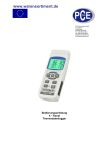
www.pce-industrial-needs.com Tursdale Technical Services Ltd Unit N12B Tursdale Business Park Co. Durham DH6 5PG United Kingdom Phone: +44 ( 0 ) 191 377 3398 Fax: +44 ( 0 ) 191 377 3357 [email protected] http://www.industrial-needs.com/ Manual Digital Thermometer PCE-T 390 [email protected] Table of contents 1. 2. Features ............................................................................................................................................ 3 Specifications .................................................................................................................................. 3 2-1 General Specifications ..................................................................................................................... 3 2-2 Electrical Specifications (23± 5 Ԩ) .................................................................................................. 6 3. Front Panel Description ...................................................................................................................... 7 4. Measuring Procedure........................................................................................................................ 8 4-1 Type K measurement ....................................................................................................................... 8 4-2 Type J/T/E/R/S measurement........................................................................................................... 8 4-3 Pt 100 ohm measurement ................................................................................................................. 8 4-4 T1-T2 measurement ......................................................................................................................... 8 4-5 Data Hold ........................................................................................................................................ 9 4-6 Data Record ( Max., Min. reading ).................................................................................................. 9 4-7 LCD Backlight ON/OFF .................................................................................................................. 9 5. Datalogger ........................................................................................................................................ 9 5-1 Preparation before execute datalogger function ................................................................................ 9 5-2 Auto Datalogger ( Set sampling time ؤ1 second ) ................................................................... 10 5-3 Manual Datalogger (Set sampling time = 0 second) ................................................................... 10 5-4 Check time information ................................................................................................................. 11 5-5 Check sampling time information .................................................................................................. 11 5-6 SD Card Data structure .................................................................................................................. 11 6. Saving data from the SD card to the computer (EXCEL software)............................................. 11 EXCEL data screen ( for example ) ....................................................................................................... 12 7. Advanced Setting ........................................................................................................................... 12 7-1 Set clock time (Year/Month/Date, Hour/Minute/ Second)............................................................... 13 7-2 Decimal point of SD card setting ................................................................................................... 13 7-3 Auto power OFF management ....................................................................................................... 13 7-4 Set beeper sound ON/OFF ............................................................................................................. 13 7-5 Select the Temp. unit to Cº or Fº .................................................................................................... 14 7-6 Set sampling time (Seconds) .......................................................................................................... 14 7-7 SD memory card Format ................................................................................................................ 14 8. Power Supply from DC Adapter ....................................................................................................... 14 9. Battery Replacement ......................................................................................................................... 14 10. RS232 PC Serial Interface ............................................................................................................... 15 11. Offeset Adjustment .......................................................................................................................... 16 11-1 Type K/J/T/E/R/S offset adjustment ............................................................................................. 16 11-2 Pt 100 ohm offset adjustment ....................................................................................................... 16 12. Optional Type K Temp. probe ........................................................................................................ 17 13. Patent ............................................................................................................................................... 18 2 [email protected] 1. Features * Type K/J/T/E/R/S, Pt 100 ohm, measurement with 4 display. * Show 4 channels display on the LCD at the same time. * Type K: -100 to 1300 ℃. * Type J: -100 to 1200 ℃. * Pt 100 ohm: -199.9 to 850.0 ℃. * ℃/℉, 0.1 degree/1 degree. * 4 channels (T1, T2, T3, T4 ), T1-T2. * Microcomputer circuit provides intelligent function and high accuracy. * Offset adjustment for the Type K/J/T/E/R/S measurement. * Offset adjustment for the Pt 100 measurement. * Measuring unit can select to ℃ or ℉. * Real time SD memory card Datalogger, it Built-in Clock and Calendar, real time data recorder, sampling time set from 1 second to 3600 seconds. * Manual datalogger is available (set the sampling time to 0 second), during execute the manual datalogger function, it can set the different position (location) No. (position 1 to position 99). * Innovation and easy operation, computer is not need to setup extra software, after execute datalogger, just take away the SD card from the meter and plug in the SD card into the computer, it can down load the all the measured value with the time information ( year/month/date/ hour/minute/second ) to the Excel directly, then user can make the further data or graphic analysis by themselves. * SD card capacity: 1 GB to 16 GB. * LCD with green light backlight, easy reading. * Can default auto power off or manual power off. * Data hold, record max. and min. reading. * Microcomputer circuit, high accuracy. * Power by UM3/AA (1.5 V) x 6 batteries or DC 9V adapter. * RS232/USB PC COMPUTER interface. * Heavy duty & compact housing case. 2. Specifications 2-1 General Specifications 3 [email protected] Circuit Display Channels Sensor type Resolution Datalogger Sampling Time Setting range Custom one-chip of microprocessor LSI circuit. LCD size : 52 mm x 38 mm LCD with green backlight ( ON/OFF ). T1, T2, T3, T4, T1-T2. Type K thermocouple probe. Type J/T/E/R/S thermocouple probe. PT 100 ohm probe * Cooperate with an 0.00385 alpha coefficient, meet DIN IEC 751. 0.1Ԩ /1Ԩ, 0.1Ԭ/1 Ԭ. Auto 1 second to 3600 seconds @ Sampling time can set to 1 second, but memory data may loss. Manual Push the data logger button once will save data one time. @ Set the sampling time to 0 second. @ Manual mode, can also select the 1 to 99 position ( Location ) no. Memory Card Advanced setting SD memory card. 1 GB to 16 GB. * Set clock time ( Year/Month/Date, Hour/Minute/ Second ) * Decimal point of SD card setting * Auto power OFF management * Set beep Sound ON/OFF * Set temperature unit to Cº or Fº * Set sampling time * SD memory card Format 4 [email protected] Temperature Compensation Linear Compensation Offset Adjustment Probe Input Socket Automatic temp. compensation for the type K/J/T/E/R/S thermometer. Linear Compensation for the full range. Over Indication Data Hold Memory Recall Sampling Time of Display Data Output Show " - - - - ". Freeze the display reading. Maximum & Minimum value. Approx. 1 second. Power off Operating Temperature Operating Humidity Power Supply Available for Type K/J/T/E/R/S and Pt 100 ohm. Type K/J/T/E/R/S 2 pin thermocouple socket. Pt 100 ohm : Ear phone socket. RS 232/USB PC computer interface. * Connect the optional RS232 cable UPCB-02 will get the RS232 plug. * Connect the optional USB cable USB-01 will get the USB plug. Auto shut off saves battery life or manual off by push button. 0 to 50 Cº. Less than 85% R.H. * Alkaline or heavy duty DC 1.5 V battery ( UM3, AA ) x 6 PCs, or equivalent. * DC 9V adapter input. ( AC/DC power adapter is optional ). Power Current Normal operation ( w/o SD card save data and LCD Backlight is OFF) : Approx. DC 8.5 mA. When SD card save the data but and LCD Backlight is OFF) : Approx. DC 30 mA. * If LCD backlight on, the power consumption will increase approx. 14 mA. 489 g/1.08 LB. Weight 177 x 68 x 45 mm Dimension (7.0 x 2.7x 1.9 inch) Accessories * Instruction manual......................1 PC Included 5 [email protected] Optional Accessories * Type K thermocouple probe. TP-01, TP-02A. TP-03, TP-04 * Pt 100 ohm probe, TP-101. * SD Card ( 1 GB ) * SD Card ( 2 GB ) * USB cable, USB-01. * RS232 cable, UPCB-02. * Data Acquisition software, SW-U801-WIN. * AC to DC 9V adapter. * Hard carrying case, CA-06. * Soft carrying case, CA-05A. 2-2 Electrical Specifications (23± 5 ℃) PT 100 ohm: Resolution Range Accuracy 0.1 Cº -199.9 to 850.0 Cº ± ( 0.4 % + 1 Cº ) 0.1 Fº -327.0 to 999.9 Fº ± ( 0.4 % + 1.8 Fº ) 1 Fº 1000 to 1562 Fº ± ( 0.4 % + 2 Fº ) * Pt 100 ohm probe TP-101 is the optional accessory. Type K/J/T/E/R/S: Sensor Resolutio Range n Type Type K 0.1 Cº -50.1 to -100.0Cº -50.0 to 999.9 Cº 1 Cº 1000 to 1300 Cº 0.1 Fº -58.1 to -148.0Fº -58.0 to 999.9 Fº Fº 1 1000 to 2372 Fº Type J 0.1 Cº -50.1 to -100.0Ԩ -50.0 to 999.9Ԩ 1 Cº 1000 to 1150Ԩ 0.1 Ԭ -58.1 to -148.0 Ԭ -58.0 to 999.9 Ԭ 1Ԭ 1000 to 2102 Fº Type T 0.1 Ԩ -50.1 to -100.0 Ԩ -50.0 to 400.0 Ԩ 0.1 Ԭ -58.1 to -148.0 Ԭ -58.0 to 752.0 Ԭ Type E 0.1 Ԩ -50.1 to -100.0 Ԩ -50.0 to 900.0 Ԩ 0.1 Ԭ -58.1 to -148.0 Ԭ -58.0 to 999.9 Ԭ 1Ԭ 1000 to 1652 Ԭ Type R 1 Ԩ 0 to 600 Ԩ 601 to 1700 Ԩ 1Ԭ 32 to 1112 Ԭ 1113 to 3092 Accuracy ± ± ± ± ± ± ± ± ± ± ± ± ± ± ± ± ± ± ± ± ± ± ± ± ± ( 0.4 % + 1 Cº ) ( 0.4 % + 0.5 Cº ) ( 0.4 % + 1 Cº ) ( 0.4 % + 1.8 Fº ) ( 0.4 % + 1 Fº ) ( 0.4 % + 2 Fº ) ( 0.4 % + 1 Ԩ ) ( 0.4 % + 0.5 Ԩ ) ( 0.4 % + 1 Ԩ ) ( 0.4 % + 1.8 Ԭ ) ( 0.4 % + 1 Ԭ ) ( 0.4 % + 2 Ԭ ) ( 0.4 % + 1 Ԩ ) ( 0.4 % + 0.5 Ԩ ) ( 0.4 % + 1.8 Ԭ ) ( 0.4 % + 1 Ԭ ) ( 0.4 % + 1 Ԩ ) ( 0.4 % + 0.5 Ԩ ) ( 0.4 % + 1.8 Ԭ ) ( 0.4 % + 1 Ԭ ) ( 0.4 % + 2 Ԭ ) ( 0.5 % + 1 Ԩ ) ( 0.5 % + 1 Ԩ ) ( 0.5 % + 2 Ԭ ) ( 0.5 % + 2 Ԭ ) 6 [email protected] T Type S 1Ԩ 1Ԭ 0 to 600 Ԩ 601 to 1500 0Ԩ 32 to 1112 Ԭ 1113 to 273 32Ԭ ± ± ± ± ( 0.5 5%+1Ԩ) ( 0.5 5%+1Ԩ) ( 0.5 5%+2Ԭ) ( 0.5 5%+2Ԭ) Remark : R a. Accuraccy value is specified s for the meter only. b. Accuraccy is tested under the meter's m enviro onment tempera ature within 23 ± 5 Cº. c. Linearitty Correction n: Memorize the therm mocouple's curve c into the e intelligent CPU @Abovve specificattion tests un nder the envvironment RF Field Stre ength less th han 3 V/M & frequency less tha an 30 MHz only. o 3. Frontt Panel Description 3-1 Dissplay. 3-2 Pow wer Button ( ESC, Baccklight Butto on ) 3-3 Ho old Button ( Next Button n) 3-4 RE EC Button ( Enter Butto on ) 3-5 Typ pe Button ( ▲ Button, L Button ) 3-6 T1--T2 Button ( ▼ Button,, R Button ) 3-7 SE ET Button ( Time checkk Button ) 3-8 Log gger Button n ( OFFSET Button, Sampling time e check Buttton) 3-9 T1,T2,T3,T4 in nput socket ( Type K, Type T J) 3-10 PT1 input socket ( Pt 10 00 ohm ) 3-11 PT2 input socket ( Pt 10 00 ohm ) 3-12 RS-232 R output terminal 3-13 DC 9V adaptter socket 3-14 Trripod Fix Nu ut 3-15 Battery Cove er Screws 7 [email protected] 3-16 Battery compartment/Cover 3-17 Stand 3-18 SD card socket 4. Measuring Procedure 4-1 Type K measurement 1) Power on the meter by pressing the "Power button" (3-2, Fig. 1) once. * After already power on the meter, pressing the "Power button" once (> 2 sec) will turn off the meter. 2) Meter default Temp. sensor type is Type K, the display will show " K " indicator. The default temperature unit is Cº (Fº), the method to change the Temp. unit from Cº to Fº or Fº please refer to Chapter 7-5, page 18. 3) Insert the Type K probes into the " T1, T2, T3, T4 input socket " ( 3-9, Fig. 1 ). The LCD will show the 4 channels ( T1, T2, T3, T4 ) temperature value at the same time. * If the certain channels do not insert the temperature probes, the relative channel display will show over range " - - - - - ". 4-2 Type J/T/E/R/S measurement All the measuring procedures are same as the Type K (section 4-1) except to select the Temp. Sensor type to "Type J/K/T/E/R/S" by pressing the "Type Button" (3-5, Fig. 1) once in sequence until the up LCD display show "J/T/E/R/S" indicator. 4-3 Pt 100 ohm measurement 1) All the measuring procedures are same as the Type K (section 4-1) except to select the Temp. Sensor type to "Pt" by pressing the "Type Button" (3-5, Fig. 1) once in sequence until the right down LCD display show " Pt " text as : PT 2) Insert the Pt 100 ohm probe ( optional, PT-101 ) to PT1 input socket ( 3-10, Fig. 1 ) PT2 input socket ( 3-11, Fig. 1 ) * The Pt 100 ohm measurement only allow max. two channels ( two probes ) input. 4-4 T1-T2 measurement If the meter already insert two probes: Type K/J/T/E/R/S : T1, T2 input socket Pt 100 ohm : PT1, PT2 input socket Pressing the " T1-T2 button " ( 3-6, Fig. 1 ), display will show the difference temperature value between T1, T2 (PT1, PT2) as : 8 [email protected] 4-5 Data Hold During the measurement, press the " Hold Button " ( 3-3, Fig. 1 ) once will hold the measured value & the LCD will display a " HOLD " symbol. Press the " Hold Button " once again will release the data hold function. 4-6 Data Record ( Max., Min. reading ) 1) The data record function records the maximum and minimum readings. Press the " REC Button " ( 3-4, Fig. once to start the Data Record function and there will be a " REC " symbol on the display. 2) With the " REC " symbol on the display : a) Press the " REC Button " ( 3-4, Fig. 1 ) once, the " REC MAX " symbol along with the maximum value will appear on the display. If intend to delete the maximum value, just press the " Hold Button " ( 3-3, Fig. 1 ) once, the display will show the " REC " symbol only & execute the memory function continuously. b) Press the " REC Button " ( 3-4, Fig. 1 ) again, the " REC MIN " symbol along with the minimum value will appear on the display. If intend to delete the minimum value, just press the " Hold Button " ( 3-3, Fig. 1 ) once, the display will show the " REC " symbol only & execute the memory function continuously. c) To exit the memory record function, just press the " REC " button > 2 seconds at least. The display will revert to the current reading. 4-7 LCD Backlight ON/OFF After power ON, the "LCD Backlight" will light automatically. During the measurement, press the "Backlight Button" (3-2, Fig. 1) once will turn OFF the "LCD Backlight". Press the "Backlight Button" once again will turn ON the" LCD Backlight" again. 5. Datalogger 5-1 Preparation before execute datalogger function a. Insert the SD card Prepare a "SD memory card" (1 GB to 16 GB, optional), insert the SD card into the "SD card socket" (3-18, Fig. 1). The front panel of the SD card should face against the down case. b. SD card Format If SD card just the first time use into the meter, it recommend to make the "SD card Format" at first. , please refer chapter 7-7 ( page 19 ). 9 [email protected] c. Time setting If the meter is used at first time, it should to adjust the clock time exactly, please refer chapter 7-1 ( page 16 ). d. Decimal format setting The numerical data structure of SD card is default used the as the decimal, for example "20.6" "1000.53". But in certain countries (Europe ...) is used the " , " as the decimal point, for example " 20, 6 " "1000,53". Under such situation, it should change the Decimal character at first, details of setting the Decimal point, refer to Chapter 7-2, page 17. 5-2 Auto Datalogger ( Set sampling time ≧ 1 second ) a. Start the datalogger Press the " REC Button ( 3-4, Fig. 1 ) once , the LCD will show the text " REC ", then press the " Logger Button " ( 3-8, Fig. 1 ), the " REC " will flashing and beeper will sound, at the same time the measuring data along the time information will be saved into the memory circuit. Remark: * How to set the sampling time, refer to Chapter 7-6, page 19. * How to set the beeper sound is enable, refer to Chapter 7-4, page 18. b. Pause the datalogger During execute the Datalogger function , if press the " Logger Button " ( 3-8, Fig. 1 ) once will pause the Datalogger function ( stop to save the measuring data into the memory circuit temporally ). In the same time the text of " REC " will stop flashing. Remark :If press the " Logger Button " ( 3-8, Fig. 1 ) once again will execute the Datalogger again, the text of " REC " will flashing. c.. Finish the datalogger During pause the Datalogger, press the " REC Button " ( 3-4, Fig. 1) continuously at least two seconds, the " REC " indicator will be disappeared and finish the Datalogger. 5-3 Manual Datalogger (Set sampling time = 0 second) a. Set sampling time is to 0 second Press the " REC Button ( 3-4, Fig. 1 ) once , the LCD will show the text " REC ", then press the " Logger Button " ( 3-8, Fig. 1 ) once, the " REC " will flashing once and Beeper will sound once, at the same time the measuring data along the time information and the Position no. will be saved into the memory circuit. Remark: * For the 4 channels measurement, the right lower Display will show the Position/Location no. (P1, P2... P99) and the T4 measurement value alternately. * During execute the Manual Datalogger, use the " ▲ Button " ( 3-5, Fig. 1) or " ▼ Button " (3-6, Fig. 1 ) to set the measuring position (1 to 99, for example room 1 to room 99 ) to identify the measurement location. b. Finish the Datalogger Press the "REC Button " ( 3-4, Fig. 1) continuously at least two seconds, the " REC " indication will be disappeared and finish the Datalogger. 10 [email protected] 5-4 Check time information During the normal measurement (not execute the Datalogger), If press "Time check Button" (37, Fig.1) once, the lower LCD display will present the time information of Year/Month, Date/Hour, Minute/Second. 5-5 Check sampling time information During the normal measurement ( not execute the Datalogger ), If press " Sampling Button " ( 3-8, Fig. 1 ) once , the lower LCD display will present the Sampling time information in second unit. 5-6 SD Card Data structure 1) When the first time, the SD card is used into the meter, the SD card will generate a folder: TMA01 2) If the first time to execute the Datalogger, under the route TMA01\, will generate a new file name TMA01001.XLS. After exist the Datalogger, then execute again, the data will save to the TMA01001.XLS until Data column reach to 30,000 columns, then will generate a new file, for example TMA01002.XLS 3) Under the folder TMA01\, if the total files more than 99 files, will generate a new route, such as TMA02\........ 4) The file's route structure : TMA01\ TMA01001.XLS TMA01002.XLS TMA01099.XLS TMA02\ TMA02001.XLS TMA02002.XLS TMA02099.XLS TMAXX\ Remark : XX : Max. value is 10. 6. Saving data from the SD card to the computer (EXCEL software) 1) After execute the Data Logger function, take away the SD card out from the "SD card socket" ( 3-18, Fig. 1 ). 2) Plug in the SD card into the Computer's SD card slot ( if your computer build in this installation ) or insert the SD card into the " SD card adapter ". then connect the " SD card adapter " into the computer. 3) Power ON the computer and run the "EXCEL software". Down load the saving data file (for example the file name: TMA01001.XLS, TMA01002.XLS) from the SD card to the computer. The saving data will present into the EXCEL software screen (for example as following EXCEL data screens), then user can use those EXCEL data to make the further Data or Graphic analysis usefully. 11 [email protected] EXCEL data screen ( for example ) EXCEL graphic screen ( for example ) 7. Advanced Setting Under do not execute the Datalogger function, press the "SET Button " ( 3-7, Fig. 1) continuously at least two seconds will enter the " Advanced Setting " mode. then press the" Next Button " (3-3, Fig. 1 ) once a while in sequence to select the seven main function, the lower display will show : dAtE..... Set clock time (Year/Month/Date, Hour/Minute/ Second) dEC.......Set SD card Decimal character PoFF..... Auto power OFF management bEEP.....Set beeper sound ON/OFF t-CF...... Select the Temp. unit to Cº or Fº SP-t...... Set sampling time (Hour/Minute/Second) Sd F..... SD memory card Format Remark: During execute the " Advanced Setting " function, if press " ESC Button " ( 3-2, Fig. 1 ) once will exit the " Advanced Setting " function, the LCD will return to normal screen. 12 [email protected] 7-1 Set clock time (Year/Month/Date, Hour/Minute/ Second) When the lower display show "dAtE" 1) Press the " Enter Button " ( 3-4, Fig. 1 ) once, Use the " ▲ Button " ( 3-5, Fig. 1 ) or " ▼ Button" ( 3-6, Fig. 1 ) to adjust the value ( Setting start from Year value ). After the desired value is set, press the " Enter Button " ( 3-4, Fig. 1 ) once will going to next value adjustment (for example, first setting value is Year then next to adjust Month, Date, Hour, Minute, Second value). 2) After set all the time value ( Year, Month, Date, Hour, Minute, Second ), the screen will jump to " SD card Decimal character" setting screen ( Chapter 7-2 ). Remark: After the time value is setting, the internal clock will run precisely even Power is off (The battery is under normal condition, no low battery condition). 7-2 Decimal point of SD card setting The numerical data structure of SD card is default used the " . " as the decimal, for example "20.6" "1000.53" . But in certain countries ( Europe ...) is used the " , " as the decimal point, for example " 20,6 " "1000,53". Under such situation, it should change the Decimal character at first. When the lower display show "dEC" 1) Use the " ▲ Button " ( 3-5, Fig. 1 ) or " ▼ Button " ( 3-6, Fig. 1 ) to select the upper value to " bASI " or " Euro ". bASI - Use " . " as the Decimal point with default. Euro - Use " , " as the Decimal point with default. 2) After select the upper text to " bASI " or " Euro ", press the " Enter Button " ( 3-4, Fig. 1 ) will save the setting function with default. 7-3 Auto power OFF management When the lower display show " PoFF " 1) Use the " ▲ Button " ( 3-5, Fig. 1 ) or " ▼ Button " ( 3-6, Fig. 1 ) to select the upper value to "yES " or " no ". yES - Auto Power Off management will enable. no - Auto Power Off management will disable. 3) After select the upper text to " yES " or " no ", press the " Enter Button " ( 3-4, Fig. 1 ) will save the setting function with default. 7-4 Set beeper sound ON/OFF When the lower display show " bEEP " 1) Use the " ▲ Button " ( 3-5, Fig. 1 ) or "▼ Button" ( 3-6, Fig. 1 ) to select the upper value to "yES " or " no ". yES - Meter's beep sound will be ON with default. no - Meter's beep sound will be OFF with default. is power ON. 3) After select the upper text to " yES " or " no ", press the " Enter Button " ( 3-4, Fig. 1 ) will save the setting function with default. 13 [email protected] 7-5 Select the Temp. unit to Cº or Fº When the lower display show " t-CF " 1) Use the " ▲ Button " ( 3-5, Fig. 1 ) or " ▼ Button " ( 3-6, Fig. 1 ) to select the upper Display text to " C " or " F ". C - Temperature unit is Cº F - Temperature unit is Fº 2) After Display unit is selected to " C " or " F ", press the " Enter Button " ( 3-4, Fig. 1 ) will save the setting function with default. 7-6 Set sampling time (Seconds) When the lower display show " SP-t " 1) Use the " ▲ Button " ( 3-5, Fig. 1 ) or " ▼ Button " (3-6, Fig. 1 ) to adjust the value ( 0, 1, 2, 5, 10, 30,60, 120, 300, 600, 1800,3600 seconds ). Remark : If select the sampling time to " 0 second ", it is ready for manual Datalogger. 2) After the Sampling value is selected, press the "Enter Button" ( 3-4, Fig. 1 ) will save the setting function with default. 7-7 SD memory card Format When the lower display show " Sd F " 1) Use the " ▲ Button " ( 3-5, Fig. 1 ) or " ▼ Button " (3-6, Fig. 1 ) to select the upper value to " yES " or " no ". yES - Intend to format the SD memory card no - Not execute the SD memory card format 2) If select the upper to " yES ", press the " Enter Button " ( 3-4, Fig. 1 ) once again, the Display will show text " yES Ent " to confirm again, if make sure to do the SD memory card format, then press " Enter Button " once will format the SD memory clear all the existing data that already saving into the SD card. 8. Power Supply from DC Adapter The meter also can supply the power supply from the DC 9V Power Adapter ( optional ). Insert the plug of Power Adapter into "DC 9V Power Adapter Input Socket" ( 3-13, Fig. 1 ). The meter will permanent power ON when use the DC ADAPTER power supply (The power Button function is disable). 9. Battery Replacement 1) When the left corner of LCD display show " ", it is necessary to replace the battery. However, in-spec. measurement may still be made for several hours after low battery indicator appears before the instrument become inaccurate. 2) Loose the "Battery Cover Screws " ( 3-15, Fig. 1 ) and take away the " Battery Cover " (316, Fig. 1 ) from the instrument and remove the battery. 14 [email protected] 3) Replace with DC 1.5 V battery ( UM3, AA, Alkaline/heavy duty ) x 6 PCs, and reinstate the cover. 4) Make sure the battery cover is secured after changing the battery. 10. RS232 PC Serial Interface The instrument has RS232 PC serial interface via a 3.5 mm terminal ( 3-12, Fig. 1 ). The data output is a 16 digit stream which can be utilized for user's specific application. A RS232 lead with the following connection will be required to link the instrument with the PC serial port. The 16 digits data stream will be displayed in the following format: D15 D14 D13 D12 D11 D10 D9 D8 D7 D6 D5 D4 D3 D2 D1 D0 Each digit indicates the following status: D15 D14 Start Word 4 D13 When send the upper display data = 1 When send the lower display data = 2 Annunciator for Display ℃ = 01 ℉ = 02 Polarity 0 = Positive 1 = Negative Decimal Point(DP), position from right to the left 0 = No DP, 1= 1 DP, 2 = 2 DP, 3 = 3 DP Display reading, D1 = LSD, D8 = MSD For example : If the display reading is 1234, then D8 to D1 is : 00001234 End Word D12, D11 D10 D9 D8 to D1 D0 RS232 FORMAT: 9600, N, 8, 1 Baud rate Parity Data bit no. Stop bit 9600 No parity 8 Data bits 1 Stop bit 15 [email protected] 11. Offeset Adjustment 11-1 Type K/J/T/E/R/S offset adjustment 1) Set the function to Type K (or other type J/E/R/T/S ). 2) Insert the probe to the T1 input socket ( 3-9, Fig. 1 ) 3) Pressing " Offset button " ( 3-8, Fig. 1 ) continuously at least two seconds then release, the display will show : * Use the " ▲ button "( 3-5, Fig. 1 ) " ▼ button " ( 3-6 Fig. 1 ) to adjust the desiring value on right bottom display. * Pressing " Enter button " ( 3-4, Fig. 1 ) once, the adjustment value will save into memory then return to normal measuring screen and finish the offset adjustment procedures. * The above offset adjustment for Type K/J/T/E/R/S is valid for T1, T2, T3, T4 at the same time. 11-2 Pt 100 ohm offset adjustment 1) Set the function to Pt 100 ohm. 2) Insert the Pt 100 ohm probe to the PT1 ( PT2 ) input socket. 3) Pressing " Offset button " ( 3-8, Fig. 1 ) continuously at least two seconds then release, the display will show: 4) If intend to make the offset adjustment for Pt 1, it should insert the probe to PT1 input socket. Pressing " L button " ( 3-5, Fig. 1 ) once, the display will show example as following. If intend to make the offset adjustment for Pt 2, it should insert the probe to PT2 input socket. Pressing " R button " ( 3-6, Fig. 1 ) once, the display will show example as following. 16 [email protected] * Use the " ▲ button "( 3-5, Fig. 1 ) " ▼ button " ( 3-6, Fig. 1 ) to adjust the desiring value on right bottom display. * Pressing " Enter button " ( 3-4, Fig. 1 ) once, the adjustment value will save into memory then return to normal measuring screen and finish the offset adjustment procedures. * The above offset adjustment for Pt 100 ohm is valid for PT1, PT2 individually. 12. Optional Type K Temp. probe (Type K) TP-01 Thermocouple Probe (Type K), TP-02A * Max. short-tern operating Temperature: 300 ℃ (572 ℉). * It is an ultra fast response naked-bead thermocouple suitable for many general purpose application. * Measure Range: -50 ℃ to 900 ℃, -50 ℉ to 1650 ℉. * Dimension:10cm tube, 3.2mm Dia. Thermocouple Probe (Type K), TP-03 * Measure Range: -50 ℃ to 1200 ℃, -50 ℉ to 2200 ℉. * Dimension: 10cm tube, 8mm Dia. Surface Probe (Type K), TP-04 * Measure Range: -50 ℃ to 400 ℃, -50 ℉ to 752 ℉. * Size : Temp. sensing head - 15 mm Dia. Probe length - 120 mm. 17 [email protected] 13. Patent The meter ( SD card structure ) already get patent or patent pending in following countries : Germany Nr. 20 2008 016 337.4 JAPAN 3151214 TAIWAN M 358970 M 359043 CHINA ZL 2008 2 0189918.5 ZL 2008 2 0189917.0 USA Patent pending In this direction will find a vision of the measurement technique: http://www.industrial-needs.com/measuring-instruments.htm NOTE: "This instrument doesn’t have ATEX protection, so it should not be used in potentially explosive atmospheres (powder, flammable gases)." 18