1
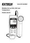
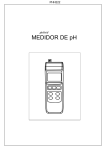
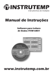
TM
User Manual
Digital Stroboscope - 72-7601
www.element14.com
www.farnell.com
www.newark.com
www.cpc.co.uk
www.mcmelectronics.com
TM
Page <1>
15/04/14
V1.0
User Manual
TM
Digital Stroboscope - 72-7601
Table Of Contents
1. Features
2. Specifications
2-1 General Specification
2-2 Flash Tube Specification
3. Front Panel Description
3-1 Flash Tube
3-2 Display
3-3A RPM Indicator
3-3B Hz Indicator
3-3C Ext. Trigger Indicator
3-4 Power On/Off Switch
3-5 AC Power Socket
3-6 Front Panel & Key Board
3-7 Fix Nut of Main Body
3-8 Fix Screw of Handgrip
3-9 Handgrip
3-10 X 2 Button
3-11 Divide by 2 Button
3-12 - Adj. Button
3-13 + Adj. Button
3-14 RPM/Hz Button
3-15 Ext./Int. Switch
3-16 Ext. Trigger Input Socket
3-17 RS232 Output Socket
3-18 Recall Button
3-19 Memory Button
3-20 Fast Finder
4. Measuring Procedures
4-1 Preparation
4-2 Checking Speed (RPM)
4-3 Checking Speed (Hz)
4-4 Memory & Recall
4-5 External trigger
5. Flash Tube Replacement
6. RS232 PC Serial Interface
www.element14.com
www.farnell.com
www.newark.com
www.cpc.co.uk
www.mcmelectronics.com
3
3&4
3&4
4
5
5
5
5
5
5
5
5
5
5
5
5
5
5
5
5
5
5
5
5
5
5
5
6
6
6
7
7
7
7
7&8
TM
Page <2>
15/04/14
V1.0
User Manual
TM
Digital Stroboscope - 72-7601
1. Features:
• T
he instrument is a microprocessor circuit design, high accuracy, digital readout Stroboscope. Adjusting the
“Flash Rate “ by push button keyboard, unique design in the world, easy operating & intelligent function. That
is ideal for inspecting and measuring the speed of moving gears, fans, centrifuges, pumps, motors and other
equipment used in general industrial maintenance, production, quality control, laboratories and as well as for
schools and colleges for demonstrating strobe action.
• External trigger input.
• RS232 computer interface output.
2. Specifications:
General Specification
Display
14mm (0.56”) LED, 5 digits
Set up unit
Flash rate - RPM ( FPM ), Hz
* FPM - flash per minute.
Flash rate set up range
RPM
5 to 12,500 RPM.
Hz
0.083 to 208 Hz
0.1 RPM
5 to 999.9 RPM.
RPM
1 RPM
1,000 to 9,999 RPM.
10 RPM
10,000 to 12,500 RPM.
Resolution
0.001 Hz
< 10 Hz
Hz
0.01 Hz
10 Hz - 99.99 Hz
0.1 Hz
100 Hz - 208 Hz
Set up stability
1 digit within 10 minute.
Switch Select
RPM, Hz
Accuracy
( 0.15 % + 0.2 RPM ) rdg.
< 1,000 RPM
( 0.5 % + 1 RPM ) rdg.
1,000 to 3,300 RPM
1 % FS.
3,301, to 12,500 RPM
rdg : reading, FS : full scale
Function
Fine adjust, Coarse adjust, Multiply by 2,
Divide by 2, Fast finder, Memory recall.
External trigger
Input signal : 5V to 30V rms,
5 to 12,500 RPM.
0.083 to 208 Hz
Memory
Memorize 10 sets of measuring data.
www.element14.com
www.farnell.com
www.newark.com
www.cpc.co.uk
www.mcmelectronics.com
TM
Page <3>
15/04/14
V1.0
User Manual
TM
Digital Stroboscope - 72-7601
Data output
RS 232 computer interface.
Power supply
AC 110V 10%, 50/60Hz.
or AC 220V 10%, 50/60Hz.
or AC 230V 10%, 50/60Hz.
Circuit
This stroboscope/tachometer employs an
custom one-chip of microcomputer LSI
circuit & crystal control time base which
results in extraordinary accuracy & high set
up stability over a wide, dynamic range.
Power consumption
Less than 30 Watt.
Operating temp.
0 to 50°C (32 to 122°F).
Operating humidity
Less than 80% R.H.
Dimension
21 × 12 × 12 cm (8.3 × 4.8 × 4.8 inch)
Weight
1Kg/2.2 LB.
Housing case
Compact and impact plastic injection case
with plastic mirror type reflector.
Calibration
Crystal time base and microprocessor
circuit, not necessary take any external
calibration procedure if the stroboscope
working properly.
Accessories included
Operation manual 1 PC.
Power cord 1 PC.
Optional Accessory
RS232 cable UPCB-02.
Flash Tube Specification
Flash tube
Xenon lamp.
Flash Duration
Approximately 60 to 1,000 microseconds.
Flash colour
Xenon white 6,500
Flash energy
4 Watts-seconds (joules).
Beam Angle
80 degrees.
Flash tube replacement
It is required to change the flash tube when
the instrument start to flash irregularly at
speeds of 3,600 RPM/FPM or more.
Operating duty Cycle
For prolong life and safety, please adhere
to the following operation duty cycle:
<2,000 RPM - 2 hours
2,000 to 3,600 RPM - one hour
3,601 to 8,000 RPM - 30 minutes
>8,000 RPM - 10 minutes.
*10min. cooling off period between cycles.
www.element14.com
www.farnell.com
www.newark.com
www.cpc.co.uk
www.mcmelectronics.com
TM
Page <4>
15/04/14
V1.0
User Manual
TM
Digital Stroboscope - 72-7601
3. Front Panel Description:
3-1 Flash Tube
3-10 X 2 Button
3-2 Display
3-11 Divide by 2 Button
3-3A RPM Indicator
3-12 - Adj. Button
3-3B Hz Indicator
3-13 + Adj. Button
3-3C Ext. Trigger Indicator
3-14 RPM/Hz Button
3-4 Power On/Off Switch
3-15 Ext./Int. Switch
3-5 AC Power Socket
3-16 Ext. Trigger Input Socket
3-6 Front Panel & Key Board
3-17 RS232 Output Socket
3-7 Fix Nut of Main Body
3-18 Recall Button
3-8 Fix Screw of Handgrip
3-19 Memory Button
3-9 Handgrip
3-20 Fast Finder
www.element14.com
www.farnell.com
www.newark.com
www.cpc.co.uk
www.mcmelectronics.com
TM
Page <5>
15/04/14
V1.0
User Manual
TM
Digital Stroboscope - 72-7601
4. Measuring Procedures:
Caution :
* Do not use the fingers or any tools to touch the Flash Tube.
* Risk of electric shock !
4-1 Preparation
a) Plug unit into a properly ACV outlet.
Caution :
* Power plug should apply the correct ACV power voltage
b) Turn the power switch to “ on “ ( 3-4, Fig. 1 ) position.
1 = Power on 0 = Power off
4-2 Checking Speed (RPM/FPM)
Caution :
* Operating duty cycle should obey.
For prolong life and safety, please adhere to the following operation duty:
<2,000 RPM - 2 hours 3,601 to 8,000 RPM - 30 min.
2,000 to 3,600 RPM - one hour >8,000 RPM - 10 min.
*10 min. cooling off period between cycles.
a) Slide the “ Ext./Int. Switch “ ( 3-15, Fig. 2 ) to the “ Int. “ position.
* Int. = Internal trigger, Ext. = External trigger
b) The “ RPM Indicator” should lit. If not, then push the “RPM/Hz Button” once a while until the “RPM Indicator” lit.
c) Fast Finder key :
If the approximate RPM values are known, then the “Fast Finder Button” can be used enabling you to reach the setting
values 100 RPM, 500 RPM, 1,000 RPM, 2,000 RPM or 5,000 RPM easily.
* The stroboscope is default to 100.0 RPM when power on.
d) X 2 Button & Divide by 2 Button :
Ref. the 3-10, 3-11 Fig. 2, use those two button to multiply & the divide the setting value easily.
e) + Adjustment Button
* Pushing the “+ Adj. Button” once will increase the setting value one count.
* Hold the “+ Adj. Button” will increase the setting value continuously. The increase speed of setting value will change
from slow to fast if hold the “+ Adj. Button” for a long time.
f) - Adjustment Button
* Pushing the “- Adj. Button” once will decrease the setting value one count.
* Hold the “- Adj. Button” will decrease the setting value continuously. The decrease speed of setting value will change
from slow to fast if hold the “ - Adj. Button “ for a long time.
g) Care must be taken when taking a measurement to ensure that the strobe is flashing in unison ( one to one ) with the
object being monitored. A Stroboscope will also stop motion at X2, X3, X4 etc.. This is referred to as harmonics. To check
the true RPM pressing the “X2 Button” and the “- 2 Button” will have the following effect.
Actual Speed
Stroboscope Setting
Multiple
Stop Motion Images
1,000 RPM
2,000 RPM/FPM
×2
2
1,000 RPM/FPM
1
1
500 RPM/FPM
-2
1
WARNING :
For accuracy it is recommended that this procedures is followed after every reading.
www.element14.com
www.farnell.com
www.newark.com
www.cpc.co.uk
www.mcmelectronics.com
TM
Page <6>
15/04/14
V1.0
User Manual
TM
Digital Stroboscope - 72-7601
4-3 Checking Speed ( Hz )
The operation procedures are same as the above “ 4-2 Checking Speed (RPM/FPM) “ except that should push the
“RPM/Hz Button” until the “ Hz Indicator” lit. Then the setting unit will be the “Hz”.
4-4 Memory & Recall
a) When checking the speed ( motion), after setting the values ( RPM or Hz ), then push the “MEMORY Button” will store
the setting values to the memory circuit.
b) Push the “Recall Button” ( 3-18, Fig. 2 ) will recall the memory values to show on the display.
c) The memory circuit can save 10 sets setting values. After power Off and On again, the memory data will disappear
from the memory circuit.
For example:
Store the setting RPM values
* When setting RPM values is 501.1 RPM, push the “MEMORY Button” first, then 501.1 RPM values will store into the first
memory circuit.
* When another setting RPM values is 1798 RPM, push the “MEMORY Button” again, then 1798 RPM values will store into
the secondary memory circuit again.
Recall the memory values
* Push the “RECALL Button”, the new setting RPM values will be the first memory data ( 501.1 RPM ).
* Push the “RECALL Button” again, the new setting RPM values be the second memory data ( 1798 RPM ).
4-5 External trigger
The stroboscope can accept the external trigger signal instead of the internal trigger ( setting the value by the push
button on the panel ).
1) If intend to accept the external trigger signal, it should select the “Ext./Int. Switch” to the “Ext.” position, at same time
the “Ext. Trigger Indicator” will lit.
2) Connect the external signal to the “Ext. Trigger Input Socket” via the earphone plug.
3) The display will show the value of the external trigger signal. Push the “RPM/Hz Button” will change external signal
unit from RPM ( RPM indicator will lit ) to Hz ( Hz indicator will lit ) or Hz to RPM.
5. Flash Tube Replacement:
It is required to change new flash tube when the instrument existing to flash irregularly at speeds of
3,600RPM ( FPM ) or more.
Caution :
* Change the tube should be done by qualify technician people only. Open the case is prohibited by user.
6. RS232 PC Serial Interface:
The instrument features an RS232 output via 3.5mm Terminal
The connector output is a 16 digit data stream which can be utilized to the user’s specific application. An RS232 lead with the
following connection will be required to link the instrument with the PC serial input.
The 16 digit data stream will be displayed in the following format:
D15 D14 D13 D12 D11 D10 D9 D8 D7 D6 D5 D4 D3 D2 D1 D0
www.element14.com
www.farnell.com
www.newark.com
www.cpc.co.uk
www.mcmelectronics.com
TM
Page <7>
15/04/14
V1.0
User Manual
TM
Digital Stroboscope - 72-7601
Each digit indicate the following status:
D0
End Word
D1 & D8
Display reading, D1 = LSD, D8 = MSD
For example :
If the display reading is 1234, then D8 to D1 is : 00001234
D9
Decimal Point (DP), position from right to the left
0 = No DP, 1= 1 DP, 2 = 2 DP, 3 = 3 DP
D10
Polarity
0 = Positive 1 = Negative
D11 & D12
Annunuciator for Display
27 = RPM
D13
1
D14
4
D15
Start Word
31 = Hz
-
RS232 FORMAT : 2400, N, 8, 1
www.element14.com
www.farnell.com
www.newark.com
www.cpc.co.uk
www.mcmelectronics.com
TM
Page <8>
15/04/14
V1.0