1
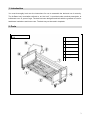
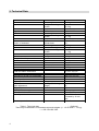
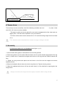
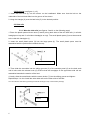
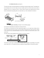
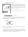
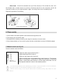
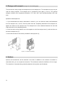
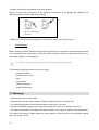
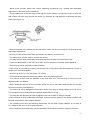
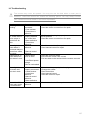
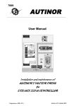
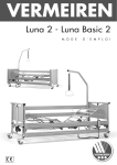
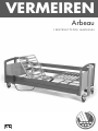
VERMEIREN Arbeau INSTRUCTION MANUAL CONTENTS 1. Introduction p.3 2. Parts p.3 3. Technical data p.4 4. Terms of use p.5 5. Assembly p.5 5.1 Bed frame and head- and footboard p.5 5.2 Bed hoist p.6 5.3 Side rails p.6 5.3.1 Wood side rails p.6 5.3.2 Metal side rails p.7 5.4 Motors p.7 5.4.1 Motor assembly p.7 5.4.1 Motor connection p.8 5.5 Head- and footboard wiring p.8 6. Disassembly p.9 7. Manual control p.9 8. Storage and transport p.10 9. Options p.10 10. Maintenance p.11 10.1 Inspection and maintenance p.11 10.2 Cleaning p.12 11. Warnings p.12 12. Explanation of symbols on the bed p.14 13. Recycling p.14 14. Motor problem troubleshooting p.15 Vermeiren NV strives to provide good products and services supported by the quality system that complies with the EN ISO 9001:2000 norm. The Ar-Beau bed combines an excellent ergonomic and functional design with simple operation. 2 1. Introduction You must thoroughly look over the instructions for use to assemble the bed and use it correctly. The Ar-Beau bed, hereinafter referred to as “the bed”, is provided under medical prescription to individuals over 12 years of age. The bed has been designed and built with the greatest of care for healthcare institutions and home care. The bed may not be used in hospitals. 2. Parts Figure 1: Assembled bed 1 Back frame 2 Leg frame 3 Headboard 4 Footboard 5 Bed hoist 6 Triangle 7 Side rails 3 3. Technical Data Back frame Leg frame Head- or footboard Bed hoist Weight of bed fully assembled Max. load dimensions total weight weight excluding motor step motor dimensions total weight weight excluding motor step motor dimensions total weight woodwork weight weight excluding motor step motor weight patient mattress accessories total load Max. bed hoist load Total bed frame dimensions Dimensions of bed fully assembled Lowest position Highest position Back adjustment Thigh adjustment Calf adjustment angle Noise production Motor operation time Electrical protection (cf. fig. 2, following page) 90 cm X 109 cm 22.6 kg 18.9 kg 10 cm 90 cm X 120 cm 22 kg 19.7 kg 5 cm 10 cm X 92 cm X 103 cm 24.7 kg 8.2 kg 21.1 kg 55 cm 7.9 kg 94 kg 150 kg 20 kg 15 kg 185 kg 80 kg 90 cm X 210 cm (*90 cm X 220 cm) 103 cm X 231 cm (*103 cm X 240 cm) 35 cm 90 cm 74° 32° 20° Max. 45 dB** Max. 10% or 2 min. Followed by 18 min. rest Class 2 Table 1: Technical data * = Optional There may be deviations in measurements and weights (+/- 1.5 cm and +/- 1.5 kg). ** = DS / EN ISO 3746 4 Figure 2: adjustment angles 4. Terms of use The bed may only be successfully used if the following conditions are met: - A power outlet with 220 V AC current must be available - The space in which the bed is placed for use must be equipped with a flat, clean and non slippery floor. The bed must be placed in a dry environment. - The floor surface area must be at least 2.8 m X 2 m and the ceiling height must be at least 2.3 m. - The 4 wheels must be blocked when someone is lying or sitting on the bed. 5. Assembly 5.1 Bed frame and head- and footboard (see figure 1, p.2) 1. Lean the bed ends against a wall and block the swivelling wheels. 2. Take the leg frame (2) of the bed. Slide the frame over the (under sawed angle) pipes of the leg frame (1). Make sure to assemble the edges and motors on the leg and back frames towards the floor. 3. Tighten the wing screws and place the bed frame on the floor with the edges and motors towards the floor. 4. Slide the footboard without sleeve (4) into the leg frame (2). Tighten the wing screws. 5. Slide the headboard with sleeve (3) into the back frame (1) of the bed frame. Again tighten the wing screws. - Always ensure that the wing screws are tightly screwed in before using the bed. 5 5.2 Bed hoist (see figure 1, p.2) 1. Insert the bed hoist (5) into the sleeve on the headboard. Make sure that the bolt on the underside of the bed hoist falls into the groove of the sleeve. 2. Hang the triangle (6) over the bed hoist (5) in the desired position. 5.3 Side rails 5.3.1. Wooden side rails (see figures 3 and 4 on the following page) 1. Place the plastic parts with two axes (3 and 4) along both sides of the two side rails (1: rail with handgrips on top and 2: rail without handgrips on top). The small plastic parts (3) must be secured to the rails with handgrips (1). 2. Insert the small plastic parts (3) into the large parts (4). The small plastic parts must be assembled with the pointed arch towards the top. Figure 3: Side rail assembly 3. Then slide the ensemble into the sliding grooves (5) of the wooden panel (8) on the bed ends until it locks with the release knob (6). Ensure that the handgrips of the uppermost side rail are assembled towards the exterior of the bed. 4. Lastly, slide the metal blocks with the screw knobs (7) into the sliding groves and tighten. Repeat steps 1 to 4 to install the other side rails on the other side of the bed. You can lower the side rails by pressing the release knob (6) on top of the wooden panel (8). Figure 4: Side rail assembly 6 5.3.2. Metal side rails (see figure 5) The metal side rails are directly attached to the bed frame using the large knobs. The distance A1 or A2 between the end of the metal rail and a wooden panel on the bed end must be either a maximum of 6 cm or a minimum of 25 cm. There is also a mark on the metal side rails. You can lower a metal side rail by pulling down on the pull knob (1) on the underside of the side rail. Figure 5: Metal side rail assembly 5.4 Motors 5.4.1 Motor assembly (see figure 6 on the following page) The motors are assembled and replaced in the same manner. The motors are connected to the bed using blocking pegs (1) on the bed frame. Motors with a control box and ports must be hung on the two edges of the back frame. Ensure that the numbers on the control box are assembled towards the top. The numbers are located above ports on the control box. The other motor must be attached to the leg frame in the same manner. Back frame Leg frame Figure 6: Side view of assembled motors Blocking peg The motors on the head- and footboards are identical and the largest in the package. The motors have a step of 55 cm. The bed end motors are attached using bolts (M10 X 43) and nuts (M10). 7 5.4.2 Motor connection (see figure 7) There are five ports in the control box on the backside of the motor. Each port is indicated with a number of letter. Connect the cables from the four motors to the correct ports. A cable number corresponds to a number shown on the top of the backside of the motor. The motor for the headboard must be connected to port 1, that for the footboard to port 2. The back frame motor must be connected to port 3 and that for the leg frame to port 4. The port indicated with an “A” is for the manual control. - The motors have a maximum use factor of 10% and a maximum continuous operation time of 2 min. per 18 min. To ensure maximum lifespan, we recommend that you respect these rules. Figure 7: Motor connection 5.5 Head- and footboard wiring (see figures 8 and 9) The motors are used to adjust the height of the bed. The bed must glide on two pipes. The two pipes retain the distance between each other through plastic wiring. The plastic wiring is located on the upper and lower sides of the head- and footboards. Figure 8: Location of wiring If you raise the bed, there could be play in the plastic wiring and they could then not function properly. You must then do the following: On top – Remove the cap (2) on top of the standing pipe. You will see a black plastic part (1) with three screws in it. If you tighten the two outer screws (3) with a socket wrench, the part will adjust to the form of the outermost pipe. Once the piece is sufficiently tightened so that the wiring has little play but is not completely stuck, close the pipe with the cap (2). 8 Underneath – Screw the unwelded nuts (4) off the thread (5). The threads are free. Turn the threads with a socket wrench so that the innermost pipe fits to the outermost. Screw the removed nut back on to its original position. Again, the wiring must not be completely stuck. Repeat the procedure if necessary. Figure 9: Wiring adjustments 6. Disassembly 1. Set the bed in the lowest position with the back and leg frames flat. 2. Pull the plug out of the wall outlet. 3. Disassemble the bed by performing the steps for assembly in reverse order. 4. Once disassembled, you can store or place the bed as described in section 8 (following page). 7. Manual control (see fig.10) Use the manual control as follows: - Adjust the back support with function 1 - Adjust bed height with function 2 - Adjust the leg support with function 3 Figure 10: Manual operation - Adjust the bed frame (anti-trendelenburg) with function 4. The function works in one direction. If you’d like to return the bed frame to horizontal position, continuously press function 2 until the bed is horizontal. You can also adjust the bed up or down to the desired position. - You must also pay attention to the individual lying in the bed. To prevent accidents, none of the individual's body parts may stick out of the bed before adjusting the head or leg supports. - When the bed is moving, no one may be under the bed. To prevent pinching, keep children at a safe distance. 9 8. Storage and transport (see figure 11 on the following page) The bed can be easily stored and transported on the transport set. The transport set may only be used for these purposes. The transport set is composed of two parts (1 and 2). The optimal storage conditions are: temperature between +5°C and +40°C and humidity between 40% and 60%. Operation of the transport set: 1. If you disassemble the bed as described in section 6, you can slide the head- and footboards into the transport set (1 and 2). Once the bed ends are completely attached to the transport set, tighten the knobs on the transport set. The transport set is then attached between the two bed ends and rests on the swivelling wheels. 2. Push the back and leg frames over the supports on the first transport set (1) and rest them on the other transport set (2). 3. Insert the bed hoist in the sleeve provided for that purpose (2). Figure 11: Transport set assembly 9. Options Options and accessories can be attached to the bed. In addition to the selection of wooden or metal side rails, you can request an extension. This extension makes the bed frame 10 cm longer. The extension is inserted during assembly between the leg frame and footboard. 10 10. Maintenance - Only your Vermeiren dealer make carry out maintenance. - No one may be sitting or lying on the bed during maintenance. 10.1 Inspection and maintenance We recommend that the bed be thoroughly controlled once per year in order to prevent accidents and optimise its lifespan. The following points must be stressed: - Good condition of your bed: verify that the back frame, leg frame, head- and footboards, bed hoist and swivelling wheels are not deformed. - Side rails: verify that the side rails are not deformed. Check that the release knob is functioning properly. The distance between the side rails in lifted position may not be greater than 12 cm. The side rails must slide in the grooves without excess friction or play. - Bed hoist: the triangle attached to the bed hoist must be replaced every five years. - Motors: check whether they provide a full step. Each motor must stop at the end of its step and may not exceed the end step. The plastic motor covering plates may not be damaged. See the motor assembly for motor replacement. - The warranty on the motors shall expire if you open the motors. - Plugs: the plugs may not be damaged or flattened. Control that the pull release on the back frame, the plugs in the power outlet box and the transformer are operating properly. - Other cables: the cables may not be damaged or flattened. - You may not use other cables than those provided with the bed to connect the motors. - The cables may only be used to connect the motors. 11 - Brakes: the blocking mechanism must work properly. Figure 12 shows the functioning of the blocking mechanism. If the brakes are released, the swivelling wheels must be able to move freely. Not blocked Blocked Figure 12: wheel blocking mechanism - Waterproof: the motor covering plates must be intact. Carry out a visual control. 10.2 Cleaning Before cleaning the bed, ensure that the plugs are pulled out of the power outlet and that all cables are connected to the control box on the back frame. Clean the bed with mild soap solutions (e.g. household cleaner or car shampoo). The motors are splash waterproof. Clean them with a moist cloth. The following cleaning products may not be used: - abrasive products - solvents (thinner, etc.) - fuels - strong acids - sodium carbonate - chlorine and bleach 11. Warnings - The bed may only be used inside. - Always ensure that the wing screws are tightly screwed in before using the bed. - The 4 swivelling wheels must be blocked when someone is in the bed. - No other individuals may be on the edge when someone is lying in or sitting on the bed. - The bed is composed of movable parts (back support, foot support, head and leg adjustment). The motors are powerful. Keep children at a safe distance. Ensure that no one becomes trapped when the bed is moved. 12 - Never press function knobs that control opposing movements (e.g. upward and downward adjustment of the back) at the same time. - The movable parts of the bed may not be near the motor cables. If you’d like to move or store the bed, always wind the plug around the hooks (1) reserved for that purpose underneath the back frame (see figure 13). Figure 13: Hooks for cable storage - When connected to the control box and the power outlet, the plug must stay out of the way during bed height adjustment. - Do not use other motors than those provided for the bed by Vermeiren NV. - The cables may only be used to connect the motors. - You may not use other cables than those provided with the bed to connect the motors. - To prevent deformation of the bed, never lean your full weight on the head- and footboards. - The bed may not be used with a water mattress. - If one motor is not working properly, pull the plug out of the power outlet and replace the motor or contact your Vermeiren dealer. - No one may be on or in the bed when it is moved. - The bed must be placed in the lowest position when the patient gets out. - The manual control must be attached to the bed after use. The bed may of course not be adjusted when not desired. - When leaving the person in the bed alone, place the bed in the lowest position and ensure that the manual control is stored away. - The bed hoist is only designed to ease the transfer from lying to sitting position and vice versa. The maximum load is 80 kg and the maximum lateral force is 35 kg. - The side rails are designed as rails for agitation and not as aids for lifting or transfer. - If an individual is lying unattended in the bed, the bed must be placed in the lowest position and the side rails must be in the highest position. - The mattress must have the following dimensions: 90 cm width, height between 12 cm and 14 cm, length of 200 cm or 210 cm with extension. - Only Vermeiren NV accessories may be assembled on the bed or used for repairs to the bed. 13 - Vermeiren NV provides parts lists, technical data, parts and exploded views. - Vermeiren NV cannot be held responsible for accidents caused by improper use. - Vermeiren NV cannot be held responsible for defective parts due to incorrect assembly or maintenance. - Contact our customer service when you need advice concerning the bed. 12. Explanation of symbols on the bed - This symbol indicates a potential risk. You must proceed with care and consult the user’s manual. - This symbol indicates that a maximum of 80 kg may be attached to the bed hoist so as not to deform the bed. - This symbol briefly explains the EN 1970 norm. It indicates the max. or min. distance between a side rail and a wooden panel. IP54 - This symbol indicates that the motors are protected against dust and water. - This symbol indicates that the bed is only designed for interior use. - This symbol indicates that the motor has extra safety fuses (type B protection). - Class 2 product 13. Recycling The bed is composed of wood, a frame of welded and powder coated steel and four motors. Consult national waste removal legislation for recycling of this apparatus after the lifespan of the bed. 14 14. Troubleshooting The motors may never be opened. You may not use the bed when a motor part is defective. These two factors can reduce the warranty period. You may always contact your certified Vermeiren dealer in the event of problems. Situation Power light is not working. Power light is not on, motor doesn’t work, relays in control box do click. Power light is on, motor doesn’t work and relays in control box make no sound. Power light is on, motor works but axis doesn’t work. Cause - Power line not connected - Fuse is blown - Control box is defective - Motor plug not properly inserted into control box - Motor defective - Control box defective - Control box defective - Manual control defective - Worm wheel loose or worn Action - Connect the power line - Send the motor or control box for repair - Confirm that the plug is properly connected in the correct position - Send the motor or control box for repair - Send the control box for repair - Send manual control for repair - Send the motor for repair - Ensure there is 220 V AC current - Put less load on the bed and let the motors rest a bit - Insufficient power voltage - Bed is overloaded Power light is on, but motor and axis don’t work. Control box OK, motor only works in one direction - Cables not properly connected - Cables broken - Control box defective - Manual control defective - Motor defective - Manual control defective - Stick the cables properly into the plugs - Change the cables - Send control box - Send manual control - Send the motor for repair - Send manual control for repair 15 Arbeau 2009-06 SERVICE The bed was serviced: Dealer´s stamp: Dealer´s stamp: Date: Date: Dealer´s stamp: Dealer´s stamp: Date: Date: Dealer´s stamp: Dealer´s stamp: Date: Date: Dealer´s stamp: Dealer´s stamp: Date: Date: Dealer´s stamp: Dealer´s stamp: Date: Date: For service checklists an additional technical information, please see our specialist dealers nearest to you. More information on our website at: www.vermeiren.com. Notes .................................................................................................................................................... .................................................................................................................................................... .................................................................................................................................................... .................................................................................................................................................... .................................................................................................................................................... .................................................................................................................................................... .................................................................................................................................................... .................................................................................................................................................... .................................................................................................................................................... .................................................................................................................................................... .................................................................................................................................................... .................................................................................................................................................... .................................................................................................................................................... .................................................................................................................................................... .................................................................................................................................................... .................................................................................................................................................... .................................................................................................................................................... .................................................................................................................................................... .................................................................................................................................................... .................................................................................................................................................... .................................................................................................................................................... .................................................................................................................................................... .................................................................................................................................................... .................................................................................................................................................... ! Notes .................................................................................................................................................... .................................................................................................................................................... .................................................................................................................................................... .................................................................................................................................................... .................................................................................................................................................... .................................................................................................................................................... .................................................................................................................................................... .................................................................................................................................................... .................................................................................................................................................... .................................................................................................................................................... .................................................................................................................................................... .................................................................................................................................................... .................................................................................................................................................... .................................................................................................................................................... .................................................................................................................................................... .................................................................................................................................................... .................................................................................................................................................... .................................................................................................................................................... .................................................................................................................................................... .................................................................................................................................................... .................................................................................................................................................... .................................................................................................................................................... .................................................................................................................................................... .................................................................................................................................................... ! Germany N.V. Vermeiren N.V. Vermeirenplein 1 / 15 B-2920 Kalmthout Tel: +32(0)3 620 20 20 Fax: +32(0)3 666 48 94 website: www.vermeiren.be e-mail: [email protected] Vermeiren Deutschland GmbH Wahlerstraße 12 a D-40472 Düsseldorf Tel: +49(0)211 94 27 90 Fax: +49(0)211 65 36 00 website: www.vermeiren.de e-mail: [email protected] France Austria Vermeiren France S.A. Z. I., 5, Rue d´Ennevelin F-59710 Avelin Tel: +33(0)3 28 55 07 98 Fax: +33(0)3 20 90 28 89 website: www.vermeiren.fr e-mail: [email protected] Vermeiren Austria GmbH Schärdinger Strasse 4 A-4061 Pasching Tel: +43(0)732 37 13 66 Fax: +43(0)732 37 13 69 website: www.vermeiren.at e-mail: [email protected] Italy Switzerland Vermeiren Italia Vermeiren Suisse S.A. Viale delle Industrie 5 I-20020 Arese MI Tel: +39 02 99 77 07 Fax: +39 02 93 58 56 17 website: www.reatime.it e-mail: [email protected] Hühnerhubelstraße 59 CH-3123 Belp Tel: +41(0)31 818 40 95 Fax: +41(0)31 818 40 98 website: www.vermeiren.ch e-mail: [email protected] Poland Spain / Portugal Vermeiren Polska Sp. z o.o ul. Łączna 1 PL-55-100 Trzebnica Tel: +48(0)71 387 42 00 Fax: +48(0)71 387 05 74 website: www.vermeiren.pl e-mail: [email protected] Vermeiren Iberica, S.L. Carratera de Cartellà, Km 0,5 Sant Gregori Parc Industrial Edifici A 17150 Sant Gregori (Girona) Tel: +34 972 42 84 33 Fax: +34 972 40 50 54 website: www.vermeiren.es e-mail: [email protected] Czech Republic Vermeiren ČR S.R.O. Nadrazni 132 702 00 Ostrava 1 Tel: +420 596 133 923 Fax: +420 596 133 277 website: www.vermeiren.cz e-mail: [email protected] R.E.: N.V. Vermeiren N.V., Vermeirenplein 1/15 - 2920 Kalmthout - Belgium – 2009-06- Instruction Manual Arbeau- vA Belgium