1
Software for the 6809 Microprocessor
board
Workshop on Distributed Laboratory
Instrumentation Systems
Abdus Salam ICTP, Trieste, November 26 - December 21, 2001
C. Verkerk, 01710 Thoiry, France
A.J. Wetherilt, Arcelik A.S., Tuzla, Istanbul
Abstract
This preliminary document describes the software available for the
ICTP 6809 board: the RJnOS multitasking kernel and the monitor
ICTPmon, both resident on the board, together with the tools for
cross-development. The RInOS kernel implements an environment for
multithreaded application programs with a well furnished set of interprocess and interthread communication mechanisms. The tools for
cross-development, running under Linux on a PC, comprise the crosscompiler, cross-assembler and linker chain, the associated libraries and
additional tools, such as a symbolic cross-debugger.
Software for the 6809 Microprocessor board
C. Verkerk and A.J. Wetherilt
Old Rinus and Jim Wetherilt were walking through some code.
They wept like anything to see obscure assembly mode.
It would be grand, they said, if C could make some road.
If seven firms with seven staff would code for half a year,
Do you suppose, old Rinus said, that they could make it clear?
I doubt it, said Jim Wetherilt, and shed a bitter tear.
With apologies to Lewis Carroll
(the Walrus and the Carpenter)
Workshop on Distributed Laboratory Instrumentation Systems,
Abdus Salam ICTP, ITrieste November 26 - December 21, 2001.
Contents
1 Introduction
10
2 User Manual for RInOS
2.1 Introduction
2.2 The IGTP09 board
2.3 An overview of RInOS
2.4 Thread / Process management
2.4.1 The Task Control Block
2.4.2 Thread Creation
2.4.3 Context switching between threads
2.4.4 Thread termination
2.4.5 Sleeping and waking threads
2.4.6 Summary of thread management system calls
2.5 Semaphore management
2.5.1 Semaphore creation
2.5.2 UP and DOWN operations
2.5.3 Other semaphore operations
2.5.4 Summary of semaphore management system calls . . .
2.6 Memory management
2.6.1 The common memory manager
2.6.2 The paged memory manager
2.6.3 Summary of memory management system calls . . . .
2.7 Interprocess communication manager
2.7.1 Messages
2.7.2 Numbered signals
2.7.3 Pipes
2.7.4 Summary of interprocess communication system calls .
2.8 Device Drivers
2.8.1 Interrupt handling within the device driver
2.8.2 The serial driver (ACIA1 and ACIA2)
2.8.3 The DAC driver
11
11
11
16
19
20
23
25
27
29
30
30
31
33
34
35
35
36
37
37
38
38
39
40
43
43
45
46
47
Software for the Ei809 Microprocessor board
C. Verkerk and A.J. Wetherilt
2.9
2.8.4 The ADC driver
2.8.5 The PIA driver
2.8.6 Installation of a new driver
The modified ASSIST09 monitor
2.9.1 ASSIST09 commands
2.9.2 The code downloader
2.9.3 Debugging with the modified ASSIST09 monitor . . . .
47
47
49
49
49
50
52
3
The
3.1
3.2
3.3
3.4
3.5
3.6
3.7
3.8
Cross-compilation Chain
The Cross-compiler
Assembler and Linker
The startup routine crtO.o
Program Libraries
The overall steering script ccO9
Downloading the program
Debuggers
Auxiliary programs
53
53
56
58
60
69
71
71
74
4
Putting it all into practice
77
4.1 Things to watch when writing a C program
77
4.2 New features added in 1999
80
4.3 Downloading and running your program
82
4.4 Debugging your program
82
4.5 Symbolic Debugging Commands
84
4.5.1 Creating a 'log' of your debugging session
84
4.5.2 Setting and using breakpoints
84
4.5.3 Removing a breakpoint
86
4.5.4 Executing your program line by line
86
4.5.5 Investigating the values of variables
87
4.5.6 Show the contents of the stack
87
4.5.7 Using an input file containing debugging commands . . 88
4.5.8 Repeating a command
88
4.5.9
Starting and exiting
89
5
Bibliography
90
6
Credits
91
A m6809 Registers and programming model
93
B Returned error codes
96
Workshop on Distributed Laboratory Instrumentation Systems.
Abdus Salam ICTP, Trieste November 26 - December 21, 2001,
Software for the 6809 Microprocessor board
C. Verkerk and A.J. Wetherilt
C System calls
98
D Device driver function calls
107
E Structure and definitions reference
111
F Linked lists used by RInOS
116
G Programming examples; assembly language
118
G.I
Create a thread using P O S I X 1003.1 compatible m e t h o d
...
118
H A debugging example
122
I
127
System calls from C
J Programming examples in C
129
J.I
A sample program using pipes
129
.1.2
A similar program using messages
132
K Assembler listing of a compiled program
135
L Example of a .map
140
file
M A debugging session with dbO9
144
N An example on-board symbolic debugging session.
152
Workshop on Distributed Laboratory Instrumentation Systems,
Abdus Salarn 1CXP, Trieste November 26 - December 21, 2001.
List of Tables
2.1
2.2
2.3
2.4
2.5
2.6
2.7
2.8
2.9
2.10
2.11
2.12
2.13
2.14
2.15
2.16
2.17
2.18
2.19
Task Control Block structure field onsets
Thread state values
Parameter structure offsets for thread creation
Stack layout before dispatching of thread
Thread attribute fields
Summary of thread management system calls
Semaphore structure definitions
Semaphore type values
Summary of semaphore management system calls
Summary of memory management system calls
Message structure offsets
Signal structure offsets
Pipe structure offsets
Summary of interprocess communication system calls
Interrupt table offsets
Device driver function requests
IOCTL usage
Device driver installation structure
Commands supported by the ICTPmon Monitor
21
22
23
24
24
30
32
33
36
37
39
39
41
43
44
45
47
49
51
3.1
3.2
3.3
3.4
3.5
3.6
3.6
3.7
3.8
3.9
3.10
3.11
Useful options to pass to the C cross-compiler
55
Options for the assembler as6809
56
Options for the linker aslink
57
Example memory layout of a compiled program
58
Functions available in libc.a
61
Interface Functions for RInOS System Calls
63
Interface Functions for RInOS System Calls Continued . . . 64
Functions available in liblO.a
64
Denominations of logical devices
65
Mathematical functions callable from a C program
66
Functions available in libgcc.a
68
Functions in libmathO9.a for internal use only.
68
Software for i,he 6809 Microprocessor board
C. Yorkerk a.nd A.J. Wetherilt
3.12 Function prototypes for libpthread.a
3.13 Options defined for the Cross-debugger dbO9
3.14 Commands supported by the Cross-debugger dbO9
69
72
74
4.1
83
Help Screen for the symbolic cross-debugger dbO9
A.I Register Set
A.2 Condition Code Register
93
93
B.I Error codes returned by 10 calls
B.2 Error codes returned by system calls
96
97
C.I
C.I
C.I
C.I
C.I
C.I
C.I
C.I
C.I
System
System
System
System
System
System
System
System
System
calls
calls
calls
calls
calls
calls
calls
calls
calls
D.I
D.I
D.I
D.I
D.2
Device
Device
Device
Device
Device
driver
driver
driver
driver
driver
E.I
E.2
E.3
E.4
E.5
E.6
E.7
E.8
E.9
E.10
E.ll
E.12
E.13
E.14
Thread Control Block (TCB) structure
Values used to define TCB fields - Thread state values . . . .
Values used to define TCB fields - Thread attribute bit fields
User settable thread attribute values
Message structure
Thread creation structure
Semaphore structure
Semaphore types used by semaphore system calls
Signal structure
Pipe structure
Interrupt table structure
System variables
Global maximum values
Hardware addresses
- Continued
- Continued
Continued
- Continued
- Continued
- Continued
- Continued
- Continued
function calls
function calls Continued
function calls -Continued
function calls Continued
definitions
Workshop on Distributed Laboratory Instrumentation Systems.
Abdus Salara ICTP, Trieste November 26 - December 21, 2001.
98
99
100
101
102
103
104
105
106
107
108
109
110
110
Ill
112
112
112
112
113
113
113
113
114
114
114
115
115
Software for the 6809 Microprocessor board
F.I Linked lists in RlnOS
F.2 Linked lists in RlnOS
I.I
I.I
C. Verkerk and A.J. Wetherilt
Continued
C functions, resulting in a system call
C functions, resulting in a system call - Continued
Workshop on Distributed Laboratory Instrumentation Systems.
Abdus Salam ICTP, Trieste November 26 - December 21, 200i.
116
117
127
128
List of Figures
2.1
2.2
2.3
Schematic Drawing of the ICTP09 board
Memory Map of the M6809 under RInOS
Jumper Settings for the ICTP09 Board
13
14
15
Chapter 1
Introduction
The 6809 Microprocessor board was developed by A J . Wetherilt, when at
the Marmara Research Centre in Istanbul, Turkey. He also developed the
RInOS multitasking kernel and the ICTPMon monitor program, which arc
both resident in EPE.OM on the board. The RInOS kernel is one of the
cornerstones of the available software, allowing a user to write programs to
a large extent compatible writh the POSIX 1003.1c standard.
The other cornerstone is the GNU C cross-compiler, which was adapted
by C. Verkerk from an existing version for the 68HC11 microprocessor. The
cross-assembler and the linker were also adapted from existing versions.
The RInOS kernel and the cross-compiler chain are independent of each
other. RInOS docs not make any assumption about characteristics of the
compiler and vice-versa. The bridge between the two is built from the various
program libraries and the C startup routine. The result is that a user can
write a multi-threaded application program without any knowledge of the
6809 microprocessor and its instruction set. The size of a single application
program is limited to just under 32 Kbytes. A maximum of 32 tasks can be
present in the system, provided the total size does not exceed 128 Kbytes
and no single program occupies more than 32 Kbytes.
Programs ; written in C or in assembly language; can be easily compiled
on the PC and downloaded to the board. They can be debugged at assembly
language level directly on the board, making use of facilities of ICTPMon.
or under Linux, using a cross-debugger dbO9.
For the future, various further extensions are planned. The most significant are: a portable version of RInOS, re-written in C, and more convenient
debugging facilities, based on gdb.
Several people contributed to this collection of software and software
tools. We mention here Carlos Kavka, Ulrich Raich, Pablo Santamarina
and Sergei Borodin. Full credit is given in the Acknowledgements,
10
Chapter 2
User Manual for RInOS
2.1
Introduction
RInOS (Real-time Integrated Operating System) is a real-time kernel designed for use with the ICTP09 board. A total of over 40 primitive functions
are available for application programs by the use of system calls. RInOS
is integrated with a modified version of the ASSIST09 monitor supplied by
the Motorola Company for use with their 6809 microprocessor. This combination of RInOS with ASSIST09 allows the downloading and debugging of
multithreaded application programs at the assembler level. A library of C
functions has been written so that the user can access all the features of the
system from a high level language. Various cross-compiler tools developed
or adapted for use with the ICTP09 board under RInOS are available.
The RInOs kernel and library interface have been designed so as to follow
closely the POSIX 1003.1c standard for threads (PThreads). Although not
yet compliant fully with the standard, many of its features have been implemented. It is hoped that both the ICTP09 board and RInOS will find use not
only as an aid to the teaching of real-time principles and methodology but
also as research and development tools in laboratory instrumentation. To
this end, the RInOS kernel is "romable1' and relatively easily adaptable to
other 6809 boards and configurations. A C version is planned for the future
that will be portable to other microprocessors.
2.2
The ICTP09 board
The 6809 board implements a large number of functions at the price of
some complexity: 24 integrated circuits are used in its construction (see
Figure 2.1). It comprises:
11
Software for the 6809 Microprocessor board
C. Verkerk and A.J. Wetherilt
• 2 serial communications ports
• 1 parallel port
• 3 timer channels
• 2 channels of 12 bit ADC input
• 2 channels of 12 bit DAC output
• 16k EPROM
• 8k base RAM
• 128k RAM arranged in 4 pages, each of 32k
The memory map of the system is shown in Figure 2.2.
The board is based around a MC6809 processor running at a clock speed
of 1 MHz. Although the 6809 is now an old microprocessor, its use in a piece
of hardware intended mainly for teaching purposes can be justified on the
grounds of its superior instruction set and clarity of use. The 6809 arguably,
still has the best instruction set of any 8 bit microprocessor or microcontroller
and is ideally suited for the current purpose. Development tools are widely
and freely available at many sites on the Internet which is a great advantage
for any device.
Throughout the design stage, stress has always been laid on those areas
that will allow the various aspects of microprocessor teaching to be emphasised. For this reason two identical serial communications ports have been
provided. These allow communications drivers to be debugged easily using
one port connected via the monitor to the host machine and the second to the
hardware application. For both ports, the baud rate can be set by changing
jumper JP2. If faster rates are required, the ACIAs at 0xA020 and 0xA030
(Figure 2.1) must be configured so that the clock is divided by 1 rather than
16 and the jumpers adjusted accordingly. Communication uses only the TxD,
E.xD and ground return lines of the RS232 9 pin ports. For interconnection
between the board and a host PC, null modem cables must be used.
The 6840 PTM provides 3 timer channels. The first is attached to the
NMI line and is used by the monitor for tracing through code, and the second
is used for the system clock by the kernel. It issues a clock interrupt on the
IRQ line at 10 ins intervals. The third clock is available to a user and has
both gate and output on the on-board standard IOTP 26 pin strip connector.
To ensure these and other interrupt signals are processed, the jumpers must
be set correctly on jumper JP1. Under RInOS, all interrupts except the
Workshop On Distributed Laboratory Instrumentation Systems.
Abdus Salam J.CTF, Trieste November 26 - December 21, 2001.
12
Software for the 6809 Microprocessor board
is—>
C. Verkerk and A.J. Wetherilt
!<t)_>
ESI -
]
L
ll
1
r
Figure 2.1: Schematic Drawing of the ICTP09 board
Workshop on Distributed Laboratory Instrumentation Systems,
Abdus Salam ICTP, Trieste November 26 - December 21, 2001,
13
Software for the 6809 Microprocessor board
C. Verkerk and A.J. Wetherilt
0
ooooo
Orflflt
00000
i
i
£
«si
>
u
Is
i **
1 m
11
0
\l
«:
Hi
0
0
r
0
_
!;
™
0z
nUJ Ul
(i)
J
1U
I 0
z
1H UJ
>
ss
0
0
0
II
5
<
,J i0
1
;tft
UJ :
W
0
r
*R
0
0
0
0
J
\>
U
:
(0
uVOFlt
0.
<
ll 1
Ul
UJ Q
Q.
DC
0
•
E
Q
z
in
UJ
0
0
Q
Ul
j
0
0
0
N
^
0
0
0
0
0
r
N
0
0
0
0
0
0
2
u
D
Ul g
5<
Figure 2.2: Memory Map of the M6809 under RInOS
Workshop on Distributed Laboratory Instrumentation Systems.
Abdus Salam ICTP, Trieste No^mber 26 - December 21, 2001,
14
Software for the 6809 Microprocessor board
C. Verkerk and A.J. Wetlierilt
JT 1
IRQ
FIRQ
IRQ
AC1A1
FIRQ
N1YII
"MONITOR
IRQ
PTM
FIRQ
IRQ
PIA
FIRQ
TliiUd Kiite
_ „ TJ
48OO
24OO
12OO
Dashed line indicates default jumper settings.
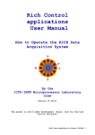
Figure 2.3: Jumper Settings for the ICTP09 Board
MON signal from timer channel 1 which is jumpered to the NMI line, must
be jumpered to the IRQ line. Jumpering to the FIRQ line without special
provision will cause unpredictable results and generally will hang the system.
Refer to Figure 2.3 for a description of the jumper settings.
Random access memory is used to provide (i) a common area for system
and application program use and (ii) an area in which large processes can be
loaded. These are supplied by a 2764 equivalent 8k RAM at 0x0000 - OxlFFF
and a 581000 128k RAM at 0x2000-0x9FFF. Since the entire address space
of the 6809 is only 64k; the 128k of the 581000 is divided into 4 pages each
of 32k in size by decoding the upper two address lines of the 581000 with an
address latch. Writing the values 0-3 to the latch will cause the appropriate
page to be set. It is advised that application processes do not interfere with
this register when the kernel is running.
Two channels each of ADC and DAC are provided. No interrupt capability is provided for the ADC channels as at a clock rate of one MHz.
conversion takes less than approximately 25 fis, which is only barely more
than the time required to handle a straight forward interrupt request. For
times longer than this, timer channel 3 can be used.
Workshop on Distributed Laboratory Inslnunofitation Systems,
Abdus Salam ICTP, Trieste November 26 - December 21, 2001.
15
Software for the 6809 Microprocessor board
2.3
C, Verkerk and A.J. Wetherilt
An overview of RInOS
Strictly speaking, RInOS comprises the kernel which holds the system dispatcher and interrupt handler together with functions for thread and semaphore management, and interprocess communications. The memory management and default device drivers rely directly on the kernel code and bypass
the regular system call mechanisms, so that it is difficult to separate them
from the kernel proper. In addition, the modified ASSIST09 also draws on
a number of kernel functions for its operation. It is possible to use the kernel without installing the monitor, but then all downloading a,nd debugging
facilities arc lost. This would be the situation for a standalone version with
user processes or threads running in ROM.
RInOS consists of the following modules:
System initialisation
System dispatcher
Hardware interrupt handler
Process/Thread management
Semaphore management
Signal and message management
Pipe management
Memory management
Device drivers
Monitor services
Memory on the ICTP09 board is organised into three separate regions:
ROM (OxcOOO-Qxffff); Common RAM (OxOOOO-Oxlfff); and Paged RAM (4x
0x2000-0x9fff). All hardware devices occupy the 8k between OxaOOO-Oxbfff.
The first 0x100 bytes of ea,ch axea of RAM are used by the memory manager
to indicate whether or not a, block of memory is in use. RInOS uses the low
portion of shared RAM starting at 0x100 to store information such as pointers
to various lists maintained by the system and flags to indicate system status.
A number of structures are defined that hold information needed by the
system. Examples of such structures are the thread control block (TCB) that
defines the state of all threads loaded by the system; blocks for semaphores,
signals, messages and so on. Those structures that are predefined by the
system reside in the low RAM area in the following order:
Task control blocks
System semaphores
Message blocks
Signal blocks
Pipe blocks
(32)
(256)
(32)
(32)
(16)
Workshop on Distributed Laboratory Instrumentation Systems.
Abdus Salam ICTP, Trieste November 26 - December 21, 2001.
16
Software for the 6809 Microprocessor board
C. Verkerk and A.J. Wetherilt
Here the bracketed quantities refer to the default number of the structures created during system initialisation. Another important structure that
resides in this area is the interrupt vector table. This table consists of an
entry for each hardware device in the system. When a hardware interrupt is
received, each device is interrogated to determine whether it was the cause of
the interruption. If so, the entries in the interrupt vector table corresponding to the device are loaded and a jump is performed to the device interrupt
function denned in the table. Since the table is in RAM, a user can change
the default behaviour by inserting new values into the table. The vector
table itself is initialised during system initialisation.
At the top 256 bytes of shared RAM, the monitor maintains its own work
area. Immediately below this, RInOS creates first the stack for the null
task and secondly the system stack. The remainder of the shared memory is
available for use by both the system and applications as required. A map of
shaxed RAM is given in Figure 2.2 on page 14.
Use of the RDM is divided into three areas. The first of these, starting at
0xc030 contains the RInOS code. The monitor resides at OxfOOO. The third
area is a table of jump vectors at 0xfff2 that is used by the 6809 processor to
vector resets and hardware and software interrupts. On initial booting, the
processor reads the value located at Oxfffe and jumps to that value. This is
the start of the monitor. After performing its initialisation, the monitor calls
the RInOS initialisation manager at 0xc030 and waits for keyboard input.
User applications are downloaded to the paged RAM area by the monitor. Two methods of loading are possible depending on whether the code
is relocatable or not. If the code is relocatable, it has an assumed origin
of 0 and must be position independent, otherwise the code must have the
absolute value 0x2200 as origin of executable code, as this is the start of
free paged memory available to the user. Only one absolute module can be
downloaded to the ICTP09 board and an error will be generated if a second
module is attempted to be downloaded. On the contrary, as many relocatable modules as desired within the available memory limits (32k per page)
can be downloaded. The system memory manager will automatically handle
the creation of all neccessary structures for the process and assign memory.
Accompanying each downloaded module is a 0x100 byte area situated immediately before the start of the memory reserved for the process. If desired,
a set of arguments from the command line can be sent with the code to be
downloaded. RInOs will make these arguments available to the application
on startup.
Once downloaded, an application program can make use of the kernel
functions by issuing a software interrupt. In assembler language, this takes
the form:
Workshop on Distributed Laboratory Instrumentation Systems.
Abdus Salaiu ICTP. Trieste November 26 - December 21, 2001.
17
Software for the 6809 Microprocessor hoard
C. Verkerk and A..I. Wetherilt
SW1
.byte
function-number
Before issuing the software interrupt, most system calls require; that various registers of the 6809 be loaded with parameters that define the action
to be performed. For example, The OSThreadCreate system call, which is
implicitly called during the downloading process, requires that the X register
points at a structure containing such items as the start of the process' code
segment, stack segment and length etc. In addition, the A register contains
the priority of the process to be created. The value following the .byte statement is a byte sized function number for the system call. A complete list of
the system calls available under RInOS is given in Table C.I on page 98. On
return from the system call. RInOS uses the carry bit in the 6809 condition
code register to indicate whether the call was completed satisfactorily. If the
carry bit is set following a system call, an error has occurred, and the A
register contains the error code number as given in Table B.I, page 96. Otherwise, when the carry bit is clear, the system call has completed normally
and the A register does not contain a valid error code, but may contain (in
some cases) a value returned by the system. A brief description of the 6809
registers and programming model can be found in Appendix A.
The process of issuing a system call from C is simplified by the provision
of a library of functions that load the registers with the required values and
issue the appropriate software interrupt.
During a system call, the processor, as an integral part of the software
interrupt call, first stacks the entire 6809 register set together with the return
address a,nd jumps to the location found at address Oxfffa, within the hardware interrupt table in ROM. This value points to a location in the monitor
which in turn points to the system dispatcher.
Once RInOS receives the request, a number of actions occur prior to
jumping to the desired system call.
Firstly, RInOS saves the current stack in the Task Control Block (TCB)
for the current thread, and switches to the system stack. It also increments
a system flag (the i n t l v l variable) to indicate that it is running in system
space and that any subsequent interrupts should not reset the stack again.
The return address is changed to the first valid instruction at the second byte
following the swi instruction. This is achieved simply by adjusting the value
of the return address on the stacked register set. Throughout the system call
it is assumed that the U register points at the base of the stacked registers
and acts as a stack frame pointer for the interrupted thread. In this way,
the register values can be accessed as desired. At this stage, the interrupt
mask bit in the 6809 processor is set so that interrupts are disabled. If this
Workshop on Distributed Laboratory Instrumentation Systems.
Abdus Salara JCTF, 'ITrieste November 26 - December 21, 2001.
18
Software for the 6809 Microprocessor board
C. Verkerk and A.J. Wetherilt
situation were to continue, no hardware interrupts could occur and the system
would not respond in the desired manner to external events. Accordingly,
the interrupt mask is cleared at the first safe opportunity. Throughout the
kernel, interrupts are enabled when possible and disabled only when it would
be dangerous to allow more than a single thread simultaneous access to the
same block of code. Such code blocks are known as critical sections and
must be carefully guarded. The next step is to clear the carry bit in the
stacked copy of the condition code register to indicate that no error ocurred
by default. A subsequent error will cause this bit to be set. otherwise it will
remain cleared. Finally, the system call number is obtained which acts as an
offset into the dispatch jump table. The address of the required function is
loaded from the dispatch table and a jump is made to that location.
Return from a system call is basically the reverse process. The 6809
stack pointer register is loaded with the saved stack value in the TCB of the
highest priority task that can run and the registers popped making control
continue following the software interrupt. The highest priority task is not
always the same task that issued the original interrupt as during processing
of the system call, the calling thread can sometimes block, that is become
temporarily suspended until some action is complete, or else another, higher
priority task can be woken which will take precedence over the first task. A
discussion of such context switching is deferred until threads are discussed
in detail in the next section.
2.4
Thread / Process management
In most multitasking systems the concepts of process and thread refer to quite
different entities; the overheads necessary to create a process being considerably larger than those needed to create a thread. Threads are generally
created within a single process and allow concurrency within that process.
Communication and synchronisation between threads within the process is
encouraged. Conversely, communication between threads created by different processes is only possible under strictly defined conditions. RlnOS does
not distinguish between thread and process creation: the two are identical.
However, the concept of threads being created by a parent process is still a
valid one under RlnOS. It will be assumed that any code downloaded using
the ASSIST09 monitor will be a process and any children it subsequently
creates will be threads. If one process can learn the identity of another, it
will be possible for the two sets of child threads to communicate. Consequently some of the terms used in the text will differ depending whether a
thread or process is being refered to. For instance, the previously mentioned
Workshop on Distributed Laboratory Instrumentation Systems.
Abdus Salam ICTP, Trieste November 26 - December 21, 2001,
19
Software for the 6809 Microprocessor board
C. Vcrkcrk and A.,I. Wetherilt
identity could be refercd to as a process identity (pid) or a thread identity
(tid) depending on the context. In fact they refer to the same object.
2.4.1
The Task Control Block
Central to thread management is the Task Control Block (TCB). This is a
structure that contains all the information needed by the system to define
and manipulate a thread. It is constructed during thread creation and is
valid during the whole life of a thread. The TCB stucture is given in Table 2.1,
page 21.
Each field of the TCB falls loosely into one of several categories depending on its function. Fields in the system category are used by RInOS for
scheduling and general thread management; fields in the semaphore and IPC
categories are used by the semaphore and signal /message managers respectively; whereas fields in the user category reflect values either set or used by
application programs.
Blank TCBs are created during system initialisation. The number of
threads that can simultaneously exist is thus set to 32. This limit can be
changed up to a maximum of 255 by altering the value HAXTASKS and reassembling. However, the current limit of 32 tasks is appropriate for most
applications considering the available hardware. In addition, a special task
known as the null thread always exists. This thread is special in that it is
always available for running and cannot block, sleep or be killed. It has a
lower priority than any other thread and therefore will run only when there
are either no other threads in existence or that no other thread can run as
a result of blocking, sleeping or other reasons. The null thread is thus the
default thread for the system and has its id field set to 1.
During system initialisation the null thread is set ready to run. This
consists of the following actions:
(i) A stack is set up for the null thread and default values for each register
are stored in the appropriate locations on the stack. The addresses of
both the start of the region reserved for the null thread stack and the
location containing the start of the register set or context are stored in
the fields STACKSEG and STACKPTR respectively. The size of the reserved
stack memory is also stored in the STACKLEN field of the TCB. When the
null task is dispatched, the system uses the information in these fields
to load the processor stack pointer register and pull the context from
the null thread stack. The final value to be pulled from the stack is the
address at which the processor will execute its next instruction. For
the null thread the memory at this address contains a single instruction
Workshop on Distributed Laboratory Instrumentation Systems,
Abdus Salam ICTP, Trieste November 26 - December 21, 2001.
20
Software for the
C. Verkerk and A.J. Wetherilt
Microprocessor board
Field
Offset
0
PPTR
Size
Category
Description
2
System
System
System
System
System
System
Link in priority list
(points to next TCB)
Instance of this thread
Thread's identification number
Priority value
Base Priority
Thread's status
Start of thread's code segment
Pointer to stack segment
Size of stack segment
Thread's stack pointer
Page number of thread
INSTANCE
2
ID
3
PRIORITY
BASEJPRIOIUTY
STATUS
4
5
6
1
1
1
1
1
CODESEG
STAGKSEG
STACKSIZE
STACKPTR
PAGE
9
11
13
15
2
2
2
2
1
System
System
System
System
System
PARENT
EXITSTS
EXITCODE
EXITFUNC
EFARG
16
17
18
19
21
2
1
1
2
2
User
User
User
User
User
Parent of thread
Exit status of thread
Return code of thread
Pointer to thread's exit function
Pointer to exit function's argument
MAILBOX
SEMALNK
TIMRCNT
TIMRLNK
ESEMALNK
23
25
27
29
31
2
2
2
2
2
IPC
Semaph.
System
System
Semaph.
SEMAOWND
33
2
Semaph.
Pointer to mailbox
Link to chain of semaphores
Sleeping time
Link to timer list
Link to threads waiting for
termination
Link to list of semaphores
owned by thread
SEMAWAIT
35
2
Semaph
MSGSEMA
37
1
IPC
ERRORSTS
ATTRIBUTE
38
39
1
1
User
User/Sys
Pointer to semaphore thread
is waiting to own
Message queue counting semaphore
Last error status
Thread's set of attributes
Table 2.1: Task Control Bloek structure field offsets
Workshop on Distributed Laboratory Instrumentation Systems.
Abdus Salam ICTP, Trieste November 26 - December 21, 2001.
21
Software for the 6809 Microprocessor board
C. Verkerk and A,J. Wetherilt
that performs a tight loop forcing the processor continually to jump to
itself. This address is in RAM at 0x012e so that breakpoints can be
set on the null thread for debugging.
(ii) The STATUS field is cleared indicating that the null thread is capable
of being run when scheduled to do so. The STATUS field is used to
indicate the thread state; a non zero value indicates some condition
preventing the thread from being run. Possible values for this field are
given in Table 2.2, page 22. The null thread can only take the value
zero since it is always runnable. Other threads, however, can have any
values depending on the current state. Prior to creation (and when
totally dead) a TCB will show the value JIOTASK (0x80) indicating that
this TCB is eligible for use. A :zombie' thread is one which has finished
its activity but has the possibility that other threads will wait for its
demise and therefore cannot release its TCB entirely. Such a thread
will have the value -SUSPEND (OxcO). A thread put to sleep will show
the value .SLEEPING (0x06) and a blocked thread will indicate _WAIT
(0x04). The final legal value, .IDLE (0x02), is used by the system to
indicate that a TCB has been reserved for use but is not yet runnable.
State
JSTOTASK
.SUSPEND
.WAIT
.SLEEPING
JDLE
_READY
Value
0x80
OxCO
0x04
0x06
0x01
0x00
Description
TCB not used
Thread suspended
Thread blocked
Thread sleeping
TCB claimed but not yet running
Thread running or waiting to run
Table 2.2: Thread state values
(iii) The priority value is set in the PRIORITY field and the TCB is linked into
the system priority list. RInOS maintains a linked list of TCBs starting
with the system variable p r i o p t r and linked using the TCB PPTR field.
Thus p r i o p t r points at the highest priority thread in the system, that
is the thread having the largest value in the PRIORITY field. In turn, the
PPTR field of this TCB points at the next highest priority thread, and so
on. The final TCB in the chain is that of the null thread, which having
the lowest priority of any thread has its PPTR field set to zero or null.
During initialisation, the null thread is the only thread in the linked
list and p r i o p t r points directly at the null thread. Subsequently, as
other threads are created, they are inserted at appropriate points in
the list.
Workshop on Distributed Laboratory Instrumentation Systems.
Abdus Salam ICTP, Trieste November 26 - December 21, 2001.
22
Software for l.hc S809 Microprocessor board
Field
PSEG
CSEG
SSEG
SLEN
CSTART
ARGPTR
TPRIO
TPID
TMEM
TATTR
TDP
Offset
0
1
3
5
7
9
11
12
14
16
17
Size
1
2
2
2
2
2
1
2
2
1
1
C. Verknrk and A.J. Wetherilt
Description
Page register value for the thread
Start of Code segment / Module
Stack segment
Stack length
Entry point of code
Pointer to thread's Argument /Environment block
Requested priority
Thread's pid (OSThreadlnstall only)
Memory size requested (OSThreadlnstall only)
Initial thread attributes
Thread's direct page
Table 2.3: Parameter structure offsets for thread creation
2.4.2
Thread Creation
The process of thread creation by an application program or the monitor arc
identical and similar to that of the creation of the null thread during system
initialisation. Whereas the null thread takes values from the system to fill its
various fields, these values must be supplied for other threads by the user.
This takes the form of supplying a table of values that the thread creation
function can access to obtain the information it needs to perform its task.
This structure is given in Table 2.3, page 23.
Under RlnOS threads are created using code already loaded and in position (the monitor only creates the thread after it has downloaded the code).
This means that RlnOS must be told where the code can be found. This
is done by the use of the PSEG and CSEG fields of the Thread Parameter
Table (TPT). These provide the page and the start of the code used by the
thread respectively and are copied directly into the PAGE and CQDESEG fields
of the selected TCB. Similarly, the start and length of the stack segment given
by SSEG and SLEN are copied into STACKSEG and STACKLEN in the TCB. The
actual entry point of the code to be executed by the thread is specified by
the CSTART field and is copied into the initial thread context set up on its
stack. RlnOS accepts arguments to a thread in the form of a pointer to the
arguments in the ARGPTR field of the TPT. This address is pushed onto the
stack prior to the register set. In addition, the address of the function that
is called when the thread terminates is also pushed onto the stack after the
argument pointer but before the context. The complete initial stack then
appears as in Table 2.4. page 24. When the thread is dispatched, the context
Workshop on Distributed Laboratory Instrumentation Systems.
Abdus Salam ICTP, Trieste November 26 - December 21, 2001.
23
Software for the 6809 Microprocessor board
C. Verkerk and A.J. Wetherilt
Position
Contents
S+14
Arg. Pointer
S+12
Return Addr.
Thread's PC
S+10
U Reg.
S+8
S+6
Y Reg.
S+4
X Reg.
S+3
DP Reg.
S+2
B Reg.
A Reg.
S+l
CC
Reg.
s
Table 2.4: Stack layout before dispatching of thread
Attribute
Value Description
DETACH-STATE
0x01 Detach state bit
CANCEL-STATE
0x02 Cancelation state bit
CANCEL.TYPE
0x04 Cancellation type bit
EXIT-PENDING
0x80 Exit pending bit
CANCEL-PENDING 0x40 Cancellation pending bit
Table 2.5: Thread attribute fields
is removed and the stack ressembles the stack of a simple function call with
the return address (in this case a function in the RInOS kernel) being pointed
at by the stack pointer register and a single argument on the stack above
the return address. Certain compilers use the 6809 direct page register for
various purposes and in such cases the TDP field can be used to set the initial
value of the direct page register in the initial context. RInOS itself does not
use direct addressing and therefore can accept any value for this register.
The requested priority is set in the A register and passed to the TCB.
An important feature for POSIX 1003.1c compatibility is the ability to
set attributes for threads either dynamically or statically. Under RInOS,
those attributes that can be represented using a bit field are stored in the
ATTRIBUTE field of the TCB and set during thread creation using the TATTR
field of the TPT. Table 2.5, page 24 lists the bits of the attribute and their
usage. A full description of the properties of the various attributes is deferred
until better POSIX 1003.lc compatibility will be achieved.
The two byte pid of the thread consisting of the INSTANCE and the ID
fields of the TCB is returned in the D register to both the parent thread
Workshop on Distributed Laboratory Instrumentation Systems,
Abdus Salara ICTP. Trieste November 26 - December 21, 2001.
24
Soft.waro for the 6809 Microprocessor board
C. Verkerk and A.J. Wetlierilt
and its new child. The ID field refers to the number of the TCB in the TCB
table created during initialisation. Each time a TCB is reused by the system,
the value of the INSTANCE field is incremented by one. The combination of
INSTANCE and ID lowers the risk of false identification of a thread.
Two different functions are available for thread creation. The first of
these, OSThreadCreate allows direct creation of a thread in the manner
described shortly. The second function OSThreadlnstall allows a function
to register itself with the system and to start RInOS. This is useful for
running applications in ROM which are not downloaded by the monitor.
The steps in thread creation are:
(i) A TPT is filled out, the priority level set in the 6809 A register and the
relevant function - either 'create' or 'install' - called.
(ii) A free TCB is found. If one is not available an error is returned to the
calling thread.
(iii) A context is created using values in the TPT.
(iv) A semaphore is created for the thread's mailbox.
(v) The PARENT field is filled in using the system variables c t s k i n s t and
ctskpid which concatenated together form the parent's full pid. The
TCB fields EXITSTS, EXITCODE, EXITFNC and EFARG which refer to the
exit status, the return code from the thread, an optional termination
function and the argument to the function respectively, are set to zero
to indicate default values. The ERRORSTS field which records the error
status of the last system call made by the thread is similarly set to zero
indicating that an error has not yet occurred.
(vi) The fields TIMRCNT and TIMRLNK which are used by the system clock
to determine when a thread should be woken if it is asleep, are zeroed
as a, thread starts its life in a runnable state.
(vii) The thread is linked into the priority list behind (at lower priority) any
task with the same priority level.
(viii) The thread has its STATUS field cleared in its TCB.
(ix) The highest priority thread in a runnable state now runs. If this is
the new child, its initial context is pulled from the stack and execution
starts at the address indicated in the TPT.
2.4.3
Context switching between threads
A context switch occurs when a running process becomes preempted, blocked
or is put, to sleep. Whenever this occurs, the kernel must save sufficient inforWorkshop OTI Distributed Laboratory Instrumentation Systems.
Abdus Salarn 1CTP, Trieste November 26 - December 21, 2001.
25
Software for the 6809 Microprocessor board
C. Verkerk and. A.J, Wetherilt
mation about the running process to enable it to start again at a later time
at the position it stopped. The information that must be saved consists of
the contents of the machine registers together with the stack pointer and the
address of the next instruction that would normally be executed. Together,
this information constitutes the context. RInOS saves this information by
requiring that all access to the system is via either a software or hardware
interrupt. In both cases, the entire register set is pushed onto the current
stack and automatically saved. In addition, the particular softwaxe interrupt
selected for system usage also switches off interrupts which allows the concept of 'atomic' or indivisible system calls which can be interrupted only at
the discretion of the kernel itself; at dangerous or inconvenient times, the
system can be protected from undesirable events. The steps taken during
each system call to save the context axe as follows:
(i) The 6809 registers are loaded by the application with the desired values
and the system call issued. This causes the register set to be pushed
onto the current stack and execution to transfer (indirectly) to the
RInOS software interrupt handler.
(ii) The system variable i n t l v l is incremented to indicate the depth of
nested interrupts (both hardware and software). If it is found to be
zero prior to being incremented the current stack pointer is saved in
the STACKPTR field of the TCB and the system stack loaded. Otherwise,
the system itself has been interrupted and the system stack is already
in use. Resetting the system stack would be an error in this case and
lead to system failure.
(iii) The return address is incremented to the address following the function
number and the function number loaded.
(iv) The stacked context is made accessible by pointing at it with the 6809
U register.
(v) Interrupts are unmasked to allow the rapid processing of hardware
events.
(vi) A jump to the desired system call is made using the dispatch jump
table and the call is executed.
During the normal operation of a system call, another higher priority
thread may be made runnable by one of a number of means; it may be
woken up from sleep; it may become unblocked by some action of the system
call; or a new thread may even be created. This new thread should then be
the one that resumes execution when control is returned from the system.
When one of these happen the following sequence of actions occurs:
Workshop on Distributed Laboratory Instrumentation Systems.
Abdus Salain ICTP, Trieste November 26 - December 21, 2001.
26
Software for the 6809 Microprocessor board
C. Verkerk and A..J. VVcthorilf,
(i) If an error is indicated, the error number is stored in the ERRQRSTS field
of the current TCB and the carry bit set in the CCR byte of the current
context for return to the caller.
(ii) Interrupts are masked to prevent spurious interruptions that could destroy system information.
(iii) The i n t l v l system variable is decremented and its new value compared
with zero. If it is not zero then the current context is obtained from
the current TCB and pulled from the stack. This ensures that a context
switch cannot occur when a system call is itself interrupted.
(iv) The priority list pointed to by the p r i o p t r system variable is scanned
for the first runnable thread. Since the list is maintained in strict order
of priority, the first suitable thread will also have the highest priority.
(v) The address of the TCB of this thread is stored in the system variable
c t s k p t r to indicate that this is now the current thread and the address
of the context for the new thread loaded from the STACKPTR field of its
TCB.
(vi) The context switch finishes with the new context being pulled from
the stack and execution resuming (or starting in the case of a newly
created thread) at the appropriate point. Interrupts are unmasked as
the new CCR register is pulled from the stack.
Hardware interrupts use the same route to return back to the point of
interruption. Since context switches can also occur as a result of the asynchronous action of a hardware interrupt it is important that all code; be
written defensively, so that a.ny sections that arc sensitive to context switching are guarded. The kernel makes use of the masking of interrupts at appropriate points to perform this function and safeguard itself. Outside the
kernel, mutexes and other synchronisation mechanisms must be employed.
Hardware interrupts do not affect the context of the current thread.
2.4.4
Thread termination
A thread can terminate in one of several ways. Firstly, some threads are
expected to terminate in the same way that a function in C is expected to
return; either explicitely or implicitely issuing a return statement. Under
RInOS a thread ca,n issue a rts (return from subroutine) statement which
causes the processor to pull the address at the top of its stack into the program counter register and jump to the address. All threads have the address
of the RInOS thread termination handler pushed onto the stack during thread
Workshop on Distributed Laboratory Instrumentation Systems,
Abdus Salam ICTP, Trieste November 26 - December 21, 2001.
2/
Software for the 6809 Microprocessor board
C. Verkerk and A.J. Wetherilt
creation to allow this action. Alternatively, a thread can terminate by calling the OSThreadExit function explicitely which just calls the same thread
termination function.
Threads can also be terminated as the result of receiving the QSThreadKill
system call from another thread. The course of action resulting from one of
these commands to terminate is ultimately similar in each case with minor
differences arising only for kill condition. The common sequence of events is:
(i) A thread can return a value. This value is placed in the B register prior
to issuing the system call. RInOS places this value in the EXITCDDE
field of the TCB and subsequently into the B register of any thread
waiting for the thread to exit.
(ii) RInOS allows a terminating thread the opportunity of executing an
exit function which was previously installed using the DSAtExit system
call. The exit function takes as a parameter a pointer to an optional
argument list. The addresses of the function and its argument pointer
are stored in the TCB fields EXITFUNC and EFARG, respectively. The
default value of the EXITFUNC field is the address of a function in the
RInOS kernel that simply performs an immediate return. The exit
function is called before any other termination activity.
(iii) RInOS now initiates a number of checks to ensure that the terminating
thread owns no resources when it finally exits. Firstly, the thread is
unlinked from the priority list. This ensures that the thread cannot be
run when the termination call finishes. Secondly, the thread is removed
from the list of active timers. This act should only be necessary for a
thread receiving an OSThreadKill system call. Next, any semaphores
owned by the terminating thread are released and the thread is removed
from the waiting lists of all other semaphores.
(iv) Any threads which were waiting for this thread to end are woken
and the EXIT_PENDING bit in the ATTRIBUTE field set. The ESEMALNK
field in the TCB is the head of the list of threads waiting on the current thread. A thread is placed in this list by calling OSThreadJoin.
The value in the EXITSTS field is returned in the B register of such a
thread. The ERR.THRDKILL error is returned by any thread killed by
the OSThreadKill call.
(v) Whether or not the TCB used by the thread is returned to the pool
of available TCBs depends on the status of the DETACH^STATE bit of
the ATTRIBUTE field. If this bit is set either dynamically using the
OSSetThreadAttr system call or statically when the thread is created,
the TCB will be released and the STATUS field will be set to -N0TASK.
Workshop on Distributed Laboratory Instrumentation Systems.
Abdus Salam ICTP, Trieste November 26 - December 21, 2001.
28
Software for the 6809 Microprocessor board
C. Verkerk and A,J. Wetherilt
Otherwise, the TCB will not be reused and the thread will become a
zombie. In this case the value .SUSPEND will be placed in the STATUS
field.
(vi) Finally, the stack segment used by the thread is released back to the
pool of available memory and a context switch performed.
If an attempt is made to kill a thread using the QSThreadKill call,
several additional actions arc possible depending on the CANCEL-STATE and
CANCEL-TYPE bits of the ATTRIBUTE field. If the CANCEL-.STATE bit is cleared,
no cancellation is allowed and the system call returns the ERRJ3ADKILL error
to the caller. Otherwise the kill will succeed in one of two ways depending
on the value of the CANCEL-TYPE bit. If this bit is set to CANCEL_TYPE_ASYNC
the thread will immediately be terminated, otherwise the bit will have the
value CANCEL_TYPE-DFRD (for 'deferred') and will be killed only at a time
when it is safe to do so. To indicate this state, the CANCEL-PENDING bit is set
in the attribute. The POSIX 1003.1c standard defines certain points within
a program where cancellation can safely occur and these are discussed in a
later section. The OSCanc el Point system call allows the thread to specify
that it is safe to cancel and to perform that action if the CANCEL-PENDING
bit is set. In this way, a thread can prepare itself for cancellation.
2.4.5
Sleeping and waking threads
A thread can temporarily suspend itself from the list of runnable threads by
issuing the OSSleep system call. This call ta,kes as an argument the time (in
system clock ticks of period 0.01 s) for which the thread will be suspended.
A duration of zero ensures that the thread will sleep forever (or until woken
by another thread). When this function is called the STATUS field is set to
-SLEEPING. For non zero values of the duration, the thread is placed in the
active timer list pointed to by the system variable elktsk. The next link
and the duration are placed in the TIMRLNK and TIMRCNT fields of the TCB,
respectively. On each clock interrupt, the TIMRCNT field of each thread in the
list is decremented and any threads with timers reaching zero are removed
from the list and woken by setting the STATUS field to -READY.
Another thread can wake a sleeping thread by the use of the OSWake
system call. This call checks that the specified thread is in fact asleep and
sets its STATUSfieldto -READY if it is. The ERR_NDSLEEP error value is returned
if the thread was not asleep.
Workshop on Distributed Laboratory Instrumentation Systems,
Abdus Salam ICTP, Trieste November 26 - December 21, 2001.
29
Software for the 6809 Microprocessor board
Function
OSYield
OSThreadlnstall
OSThreadCreate
OSThreadExit
OSThreadJoin
OSThreadKill
OSSetPriority
OSSleep
OSWake
OSAtExit
OSGetTasklnfo
OSSetThreadAttr
OSCancelPoint
OSGetLastError
Number
0
12
13
14
15
16
17
18
19
25
26
27
28
29
C. Verkerk and A.J. Wetherilt
Description
Voluntarily yield to another thread
Install a thread loaded at an absolute address
Create new thread
Terminate the current thread
Wait for a specified thread to terminate
Kill a specified thread
Set the priority of the current thread
Put the current thread to sleep for specified clock ticks
Wake a specified thread
Set an exit function for the current thread
Get a pointer to the TCB of the current thread
Set the attribute of the current thread
Cancel the current thread if cancellation pending
Get last error code of the current thread
Table 2.6: Summary of thread management system calls
2.4.6
Summary of thread management system calls
A complete list of system calls used in thread management is given in Table 2.6, page 30.
2.5
Semaphore management
Semaphores are perhaps the most important ingredient in a real-time system after the mechanisms for process management in that they allow the
full use of the system facilities in a secure manner. Without the invention
of semaphores, real-time programming in particular and all multitasking activity would be radically different. Semaphores provide a means of sharing
system resources in such a way as to prevent simultaneous access to critical
regions. Although several other constructs can provide protection for these
critical regions, semaphores are perhaps better suited and more general in
nature.
A semaphore is basically a lock that can be applied to a region of code
that needs to be protected from multiple access. A user can test the lock
and claim the resource if it is free in a single, atomic, action. Once the test
on the lock has started, no other process can interrupt the test which then
runs to completion. If the resource guarded by the semaphore is free, its use
Workshop on Distributed Laboratory Instrument; at ion Systems.
Abdus Salam J.CTF, Tiieste November 26 - December 21, 2001.
30
Software for the 6809 Microprocessor hoard
C, Verkerk and A.J, Wetherilt
is given to the process requesting the resource. If the resource is already in
use, the process will block until the resource becomes free again.
Semaphores come in three basic varieties: The M u t e x or binary semapho-
re; the Counting semaphore; and the Event semaphore. Each type
shares a number of common features but has some characteristics of their
own. A semaphore is always created with an initial value. Counting semaphores can take any value between zero and a maximum value whilst Event
semaphores and Mutexes are always either zero or one. The Mutex is actually a special case of the counting semaphore with a maximum value of one.
Apart from creation and destruction, two operations are generally defined for
a semaphore: U P and DOWN. The operation of DOWN on a semaphore
tests the current value and if non zero decrements the value and allows the
process performing the operation to continue. If the value is already zero,
it is not decremented further and the calling process is blocked. The UP
operation is the reverse of this sequence and is called by a process when it
has finished with a resource. In an UP operation, if there are any processes
waiting on the semaphore, one or more (depending on the semaphore type)
of these processes is selected as the next owner of the resource and becomes
unblocked. If no process is waiting on the semaphore, its value is usuallyincremented up to its maximum allowed level. Mutexes are used whenever
two or more threads access a common resource and the state of this resource
can be changed by one of the threads. For instance, one thread could write
to a buffer, which can be read by other threads. Before a thread accesses the
buffer, it must do a DOWN on a mutex. When the thread has finished using
the buffer it must release it by performing an UP operation on the mutex.
It must be stressed that successful use of semaphores relies on all processes
cooperating together. A single anarchistic process easily can cause the whole
system to fail by holding onto resources it no longer needs. Event semaphores
are frequently used to signal the occurrence of specific actions or events. Any
process interested in receiving notification that an event has occurred can
perform a DOWN on an Event semaphore and wait for its release.
Event semaphores wake all processes waiting on them; the first to run
being the one with the highest priority. It is common to find them being
used to wait for hardware triggers; the processes block until a button is
pressed or some other event requiring attention occurs.
2.5.1
Semaphore creation
Under RInOS all three types of semaphore are implemented. Space in the
kernel is reserved for a total of 256 semaphores (referred to as numbered or
system semaphores). Some 80 of these are used by system processes such
Workshop on Distributed Laboratory Instrumentation Systems.
K Salara ICTP. Trieste November 26 - December 21, 2001.
31
Software fox the 6809 Microprocessor board
Field
SEMTYP
SEMVAL
NXTSEM
SEMOWNER
SEMOLNK
Offset
0
1
2
4
6
Size
1
1
2
2
2
C. Verkerk and A.J. Wetherilt
Description
Semaphore type
Semaphore value
Link to list of threads waiting on this sema
Current semaphore owner
Link to list of owner's semaphores
Table 2.7: Semaphore structure definitions
as messages, signals and the default device drivers and are created during
system initialisation. The remainder are ava.ila.ble for use by an application
program. Alternatively, RInOS also allows the creation of dynamic or user
semaphores using memory owned by the application. In this ease the application creates the semaphore structure given in Table 2.7, page 32 and uses
a pointer to this structure when performing operations on the semaphore.
The structure is common to both types of semaphore; the difference between
the two types being that system semaphores all ha,ve space reserved during system initialisation and are identified by a unique number whereas user
semaphores are created by the application and are identified by their address.
During semaphore creation (for both system and user types) the fields
of the semaphore structure a.re filled in with appropriate values. The system call OSCreateSem performs this task for system semaphores and returns
the semaphore identification number. For user semaphores, the application
program must perform this task. The type of the semaphore is defined by
placing the desired value from Table 2.8, page 33, into the SEMTYP field of
the semaphore. It can be seen in this table that several options are available
for Event semaphores. The simple Event behaves in an identical manner to
a Mutcx except that it wakes all processes waiting on it and sets its value
to 1. This is sometimes not the desired action: In some cases it is necessary to wake only those processes that are waiting on the semaphore when
the particular event occurs. If a process docs a DOWN on a simple Event
semaphore after the event has taken place, it will not be blocked but will
continue. In repetitive events, this type of semaphore after its first trigger
will always indicate the occurrence of the event when what is required is the
occurrence of each individual trigger. To circumvent such problems, RInOS
also uses the Resettable Event semaphore which instead of incrementing its
value to one following the event trigger, always keeps the value of zero. In
this way when a process waits for the next event in a repetitive sequence,
the occurrence of a previous event does not affect whether or not it blocks.
Somewhat more rarely encountered but nonetheless of use, is the situation
Workshop on Distributed Laboratory Instrumentation Systems.
Abdus Salam ICTP, Trieste November 26 - December 21, 2001,
32
Soft.ware for the 6809 Microprocessor board
C. Verkerk and A.J. Wcllierilt
where a single event needs to be indicated, after which the semaphore will be
disposed of. RInOS uses such semaphores internally for signal and message
handling.
Semaphore type
MUTEX
COUNT
EVENT
REVEXT
SEVENT
Value
0x01
0x02
0x04
OxOc
0x84
Description
Mutex semaphore
Counting semaphore
Event counter
Single event ; reset after use
Single event, freed after use
Table 2.8: Semaphore type values
During semaphore creation the SEMVAL field of the semaphore should be
filled with the desired initial value. This may be any value up to a limit of
255 for Counting semaphores but only either zero or one for Mutcxes and
only zero for Events. All other fields in the semaphore should be set to zero.
2.5.2
UP and DOWN operations
The DOWN operation on semaphores must guarantee that it cannot be interrupted by any other process or event. It is therefore carried out within
the kernel with all interrupts masked during the critical sections.
The process of performing a DOWN on a semaphore differs slightly depending in the semaphore type but can be summarised as follows:
(i) If the semaphore is a Mutex or an Event, the value is decremented
using a 'rotate right accumulator' instruction. This both decrements
the value and allows a test as to whether the semaphore; was previously
zero or not. If not zero, the semaphore is claimed for the calling process
by firstly writing the address of the caller in the SEMQWNER field, and
secondly, by linking the semaphore into a list of semaphores owned by
the caller. This list has its head in the SEMA0WWD field of the current
thread's TCB. The SEMDLNK field of the semaphores form the remainder
of the list: Each time a new semaphore becomes owned by a thread
the SEM0LNK field of the last semaphore is updated to point at the
new semaphore. The purpose of this list is to enable all semaphores
owned by a thread to be released should that thread terminate for
some reason. It is good practice to ensure that in the event of termination, all semaphores should have been released previously so that
this mechanism is superfluous. The system now issues a return to the
Workshop on Distributed Laboratory Instrumentation Systems.
Abdus Salam ICTP, TVieate November 26 - December 21, 2001.
33
Software for the 6809 Microprocessor board
Q. Verkerk and A..I. Wetherilt
caller. In the case of Counting semaphores, the value is also decremented and tested. If previously non zero, an immediate return to the
caller is made. Counting semaphores are not linked into the callers list
of semaphores.
(ii) In the case when the semaphore value was previously zero, the semaphore
manager now links the thread into the list of tasks waiting on the
semaphore with its head in the NXTSEM field of the semaphore and
linked using the SEMALNK field of the TCB structure. In the case of a
Mutex, the order of insertion into the list depends on the current priority of the blocked thread; the higher its priority, the nearer the front
of the list. For Event and Counting types, the thread is inserted at the
rear of the list.
(iii) Finally, the thread is put to sleep by marking the STATUS field of its
TCB with the value _WAIT a,nd a context switch performed.
The UP operation proceeds in the reverse order. It too guarantees atomicity and can not be interrupted during its critical sections.
(i) The list of processes waiting on the semaphore is first examined. If the
NXTSEM field is XULL, the value of the semaphore can be incremented
if currently below its maximum value (simple Event semaphores are
always changed to one). If the semaphore is a Mutex or an Event, the
owner of the semaphore is set to NULL, and the semaphore removed
from the thread's list of owned semaphores. A return to the caller is
then performed.
(ii) If the list of waiting threads is not empty, the first thread in the list
(in the case of Counting and Mutex semaphores) is selected as the
semaphore's next owner and the appropriate actions taken. For Event
semaphores, all threads are woken. A Mutex can also be induced to
behave as an Event by placing the value Oxff in the B register prior
to issuing a call to either DSUpSem or OSUpUserSem. This is to ensure
compatibility with certain features of the POSIX 1003.1c standard.
(iii) A context switch is now performed.
2.5.3
Other semaphore operations
A number of other operations are provided under RInOS to facilitate the use
of semaphores.
A semaphore can be released if it is no longer required. This is simple with
user semaphores, which the same as memory can be reused. However, calls
Workshop on Distributed Laboratory Instrumentation Systems.
Abdus Salam ICTP, Trieste November 26 - December 21, 2001.
34
Software for the 6809 Microprocessor board
C. Verkerk and A.J, Wetherilt
are provided for both user and system semaphores. These calls will ensure
that the correct tidying up is performed by the system and no loose pointers
remain. Sometimes, it becomes necessary to reset an Event semaphore and
OSResetESem is provided for this purpose. The: user should bear in mind
that the manual resetting of any semaphore can be a dangerous act.
In some situations it is desira,ble to have two semaphores acting in tandem
together. Using the standard system calls, it is obviously not possible to
perform atomically a DOWN on one semaphore followed by an UP on a
second. Such a requirement exists however, in the POSIX 1003.1c standard
concerning the implementation of structures known as condition variables.
The OSDownHybrid system call is provided to enable condition variables to be
constructed. It takes two arguments of pointers to semaphores and performs
a DOWN on the first followed by a,n UP on the second (assumed to be a
Mutex).
Practically, it allows a Mutex deGned as a lock guarding a semaphore
resource to be released by an application after blocking on the resource
semaphore.
2.5.4
Summary of semaphore management system calls
Table 2.9 ,page 36 gives a summary of the system calls for semaphore management.
2.6
Memory management
RInOS implements a memory manager for several reasons. Firstly, to allow
multiple processes to be downloaded to the ICTP09 board without the user
having to worry about the location of each process. Secondly, to handle
system requests for memory allocation and deallocation in a consistent and
safe manner, and lastly to form a bridge between the hardware page register
and the system. The memory manager does not rely on hardware and does
not, therefore, swap regions of memory or detect or prevent the illegal use of
memory not owned by a process. In a small embedded system there is no need
for such a mechanism. RInOS actually implements two memory managers;
one for each of the two regions of memory. They are both similar in operation,
and differ principally in the size of memory managed. Initialisation occurs
during system initialisation prior to any memory claims by the system.
Workshop on Distributed Laboratory Instrumentation Systems.
Abdus Salam ICTP, Trieste November 26 - December 21, 2001.
35
Software for the 6809 Microprocessor board
C. Verkerk and A.J. Wetherilt
Function
OS CreateS em
OSFrecSem
Number
1
2
Category
System
System
OSDownSem
3
System
OSUpSem
4
System
OSResetESem
5
System
OSFreeUserScm
39
User
OSDownUserSem
40
User
OSUpUserSem
41
User
OSResetUserESem
42
User
OSDowiiHybrid
43
User
Description
Create new system semaphore
Release existing system
semaphore
Perform a down on a given
system semaphore
Perform an up on a given
system semaphore
Reset an event system
semaphore
Release existing user
semphore
Perform a down on a given
user semaphore
Perform an up on a given
user semaphore
Reset an event user
semaphore
Down on hybrid
semaphore-mutex combination
Table 2.9: Summary of semaphore management system calls
2.6.1
The common memory manager
The common memory manager is simpler than the paged memory manager
as it has only to deal with 8 kbytes of RAM as opposed to 128 kbytes.
Its mechanism is straightforward: The first 256 bytes of common RAM is
reserved for a memory table representing the available 8 kbytes. Each byte
in the memory table therefore is mapped into 32 bytes of RAM. During
system initialisation, the entire table is filled with the value Oxff to indicate
that each 32 byte block is available for use. Next, those areas used by the
system are identified and marked with 0 (this being the id of the system).
Subsequent requests for common memory scan the table looking for blocks
large enough to accomodate the request. The algorithm is a simple scan
using the first such available block rather than the best fit or other search
strategies. Each block is marked with the id of owner to prevent its use
by another process later. Deallocation is performed similarly: A pointer to
the allocated memory together with the size of memory to free are passed
to the DSCFreeMem system call. The pointer is converted into a memory
Workshop on Distributed Laboratory Instrumentation Systems.
Abdus Salam ICTP, Trieste November 26 - December 21, 2001.
36
C. Vcrkerk arid A.J. Wetherill.
Software for the 6809 Microprocessor board
table address and the size of memory into a number of blocks. This number
of blocks starting with the address in the table are marked with Oxff to
indicate that the memory is free. If an error occurs the value ERR_CALLOC
value is returned.
2.6.2
The paged memory manager
The page register is a latch at address 0xa040. Its function is to switch
the various pages of memory as required by the loader and RInOS. Each 32
kbyte page starts at address 0x2000 and has its first 256 bytes reserved for
use as a memory table. In this case one byte of the table is mapped into 128
bytes of paged RAM and thus the smallest amount of memory that can be
dispensed by the paged memory manager is 128 bytes. When a request for
paged memory is made, the size requested is again passed to the allocation
call OSPAllocMem. Additionally, the page number (0-3) of the requested
memory is passed. If any page will do, then the value Oxff will indicate this.
The selected page is searched and if a sufficiently large block of memory is
found, it is allocated to the calling process, otherwise the ERFLPALLOC error
value is returned. Sufficient memory to hold the requested size is always
allocated if the search is successful. This means that the allocated memory
is often slightly larger than requested. The actual size allocated is returned
together with a pointer to the memory (which is null on an error) and the
page number. The allocated size should always be recorded to enable the
correct size to be freed later (If the memory will not be freed later then this
can be avoided).
2.6.3
Summary of memory management system calls
Function
OSCAllocMem
OSCFreeMem
OSPAllocMem
OSPFreeMem
Value
20
21
22
23
Description
Allocate blocks of common memory
Free blocks of common memory
Allocate blocks of paged memory
Free blocks of paged memory
Table 2.10: Summary of memory management system calls.
Workshop on Distributed Laboratory Instrumentation Systems,
Abdus SaJara ICTP. Trieste November 26 - December 21, 2001.
37
Software for the 6809 Microprocessor board
2.7
C, Verkerk and A.J. Wetherilt
Interprocess communication manager
Threads and processes need to communicate with each other in order to pass
data and other information. The life of a thread in this respect is much easier
than that of a process (in most systems) as threads, being part of the same
process, have the ability to share common data and code. Nonetheless, most
systems implement a number of mechanisms for sharing data and passing
data to other threads or processes. The simplest of these is perhaps the use of
shared memory. Data can be stored by one thread and read by another with
the minimum of overhead. Care must be exercised, however, to ensure that
both accesses are synchronised to prevent the occurrence of race conditions.
The easiest way to achieve this is to use a mutex lock to guard the shared
memory resource. Correctly applied a mutex can prevent totally any race
condititions developing in the system. Messages are another common method
of passing data. One thread dispatches a message to the mailbox of another
thread to indicate the occurrence of some event. When the receiver gets the
message, appropriate action ca,n be taken. Messages are generally intended
for a single recipient. In some cases it is necessary to notify many or all
threads of the occurrence of some event. In this case a second type of message
or signal must be sent. Finally, pipes are frequently used for communication
of streams of data between two threads. After creation a pipe can be opened
for reading by one thread and writing by another. The writer places data at
one end of the pipe and the reader removes it at the other end.
RInOS does not have system calls for shared memory a,s it is considered a
trivial matter to establish properly protected shared memory with the available primitives. However, RInOS does implement message passing, signals
and pipes for interprocess communication, and their usage is discussed in the
following sections.
2.7.1
Messages
A message is a structure with fields for holding data and other values and
is shown in Table 2.11, page 39. The data to be sent with the message are
pointed to by the MSG field of the message structure. Each message block
is initialised during system initialisation by writing a, 'one' in the MSGUSED
field to indicate that the message is free. All other fields are zeroed. When
a message is required, the message table is scanned for a free block and if
found, claimed by writing a zero in its MSGUSED field. If one is not found, the
ERFLBADMSG error is returned to the caller. Once a message block has been
claimed and the data pointer written into the MSG field it is linked into the
Workshop on Distributed Laboratory lust,™montation Systems.
Abdus Salam ICTP, Trieste November 26 - December 21, 2001.
38
Software for the 6809 Microprocessor board
Field
SENDER
NXTMSG
MSG
MSEMA
MSGUSED
Offset
0
2
4
6
8
C. Verkerk and A.J. Wetherilt
Size
2
2
2
2
1
Description
Message sender's pid
Link to next message in list
Pointer to message
Message mutex
Message is in use
Table 2.11: Message structure offsets.
Offset
0
2
Size
to to
Field
SIGPTR
SIGSEM
Description
Optional pointer to signal parameters
Pointer to EVENT semaphore
Table 2.12: Signal structure offsets.
receiver's mailbox. This is a linked list with its head in the MAILBOX field of
the receiver's TCB and linked by the NXTMSG field of the message structure.
A thread may examine its message queue at any time by performing the
OSGetMessage system call. This call examines the message queue and returns
the address of the data field of the first message block it finds. If no message
is present the thread blocks and waits on the counting semaphore given in
the MSGSEMA field of its TCB. An UP will be performed on this semaphore
whenever a message is sent to the thread, and the semaphore value indicates
the number of messages in the queue awaiting processing. A message sender
may also desire to wait until the message is read by the receiver. This can
be arranged using the QSWaitMessage system call. This creates a system
semaphore a,nd places a pointer to it in the message block at the MSEMA field.
This mutex is initialised to zero so that the sender will block when a DOWN
is performed on it. The receiver always checks this field and if a semaphore
is found, performs the necessary UP to wake the sender.
2.7.2
Numbered signals
Numbered signals are similar in many respects to messages except that they
are sent to all threads in the system. Their structure is given in Table 2.12,
page 39.
Signals under RInOS are synchronous in that a signal handler is not
invoked to intercept and process them. Rather, a thread can wait for a
particular signal to arrive by calling the OSWaitSignal system call specifying
Workshop on Disl.ribiil.cd Laboratory Instrument, a I. ion Systems.
Abdus Salam 1CTP, Trieste November 26 - December 21, 2001.
39
Software for the 6809 Microprocessor board
C. Verkerk and A.J. Wetherilt
which signal as an argument. The thread will wait on the event semaphore;
given in the SIGSEM field of the signal structure. When released, the receiver
can optionally obtain a pointer to data from the signal SIGPTR field. RInOS
does not define the meaning of any of the 32 available signals, but leaves
this up to the user. Of course all threads must agree on the meaning of each
signal.
As with all constructs using event semaphores, the decision as to whether
once used the semaphore is to be reset or always remain set has to be made.
Logically, once a signal has been sent, it should always be available to threads
that wish to check for that signal. In practical terms ; within a small system
such as the ICTP09-RInOS combination it is easy to exhaust the number of
available signals and hence be unable to send further ones. For this reason,
RInOS allows the sender to select whether a signal is to be persistent or
will be reset. In addition if a persistent signal is to be reused, it can be
reset using the DSResetSignal system call. When making the decision as
to whether persistent or non-persistent signals are to be used, it should be
remembered that all threads (both extant and to be created in the future)
can receive persistent signals but only those waiting for the signal when the
signal actually arrives will be able to receive non persistent signal.
2.7.3
Pipes
A pipe is basically a queue or fifo for holding data with suitable protection
for the queue in the form of counting semaphores to indicate full and ernpty
states and a mutex lock to guard access to all the resources of the pipe. The
pipe structure is given in Table 2.13, page 41.
A total of 16 blank pipe structures are created during system initialisation
with the PIPE.USED field set to 1. To be used by an application, a pipe must
first be created. This consists of the following steps:
(i) The list of pipes is scanned until a free one is found. When found, it
is marked as in use by clearing the PIPE-USED field. The error value
ERR_PCREATE is returned if no free pipe can be found.
(ii) At this stage the interrupts are masked off so the initialisation process
can be protected to interruption. It is critical during the creation of
a pipe, to prevent another thread from attempting to use the pipe
before it is properly initialised. The mutex lock is created first and is
initialised to zero. The interrupts are then unmasked as the critical
section has been performed. Now, if a thread tries to claim the pipe by
performing a DOWN on the lock mutex. it will block until the mutex
is released by the pipe creation function.
Workshop on Distributed Laboratory Instrumentation Systems,
Abdus Salara ICTP, Trieste November 26 - December 21, 2001,
40
Software for the 6809 Microprocessor board
10
11
12
13
14
1
i—i
PIPE_FULLS
PIPE_EMTYS
PIPEJWMTX
PIPE-RMTX
PIPEJLMTX
9
Size
1
1
2
2
2
1
1
i—i
Offset,
0
1
2
4
6
8
i—i
Field
PIPEJJSED
PIPE.WDTH
PIPE-MEM
PIPE.FRNT
PIPE.REAR
PIPE.FPOSN
PIPE.RPOSN
C. Verkerk and A.J. Welherill
1
Description
Pipe in use flag = 1 if free
Pipe width in bytes
Pointer to allocated memory
Pointer to front of buffer
Pointer to rear of buffer
Index of front
Index of rear
Full semaphore
Empty semaphore
Write semaphore lock
Read semaphore: lock
Pipe resource lock
Table 2.13: Pipe structure offsets.
(iii) Memory is now reserved in the Common RAM area to be accessible
by all threads. The amount of memory reserved is determined by the
width of the pipe requested by the calling thread. The length of the
queue is always 32 bytes long (one memory block) but the width can
be up to 25-5 bytes. An error will be generated if a pipe of zero width
is requested. The pipe width and the address of the allocated memory
are stored in the fields PIPEJWDTH and PIPEJ4EM respectively.
(iv) Two counting semaphores are created to represent FULL and EMPTY
states of the pipe. The FULL semaphore is initialised to a value
of 32 and the EMPTY semaphore to zero. When data are placed
into the queue the FULL semaphore is decremented and the EMPTY
semaphore incremented. The opposite occurs for removal of data from
the queue. Thus if a read is attempted on an empty queue, the EMPTY
semaphore with a value of zero will block. Conversely, a full queue
with a FULL semaphore value of zero will block if an attempt is made
to write to it. The semaphore numbers for the FULL and EMPTY
semaphores are placed in the pipe fields PIPE_FULLS and PIPEJEMTYS
respectively.
(v) Two pointers are established to indicate the front and rear of the
queue. The positions of the head and tail of the queue are given by
the PIPE_FPQSN and PIPE_RP0SN Gelds respectively. These are both
initialised to 32 to indicate an empty queue.
(vi) Two further mutexes are created to protect the reading and writing
Workshop on Distributed Laboratory Instrumentation Systems.
Abdus Salam ICTP, Trieste November 2G - December 21, 2001,
41
Software for the 6809 Microprocessor board
C, Verkerk and A.J. Wetherilt
ends of the pipe. Before a thread can read or write to the pipe, the
corresponding mutex should by claimed to prevent other threads from
gaining access.
(vii) Finally, the mutex lock has an UP performed on it. This signifies that
the initialisation of the pipe is complete and any threads waiting to use
it can proceed.
The pipe creation system call, OSCreatePipe, returns the pipe identifier
for use in all subsequent operations on the pipe.
Reading and writing proceed as follows:
(i) The pipe is opened for reading or writing. This consists of passing the
pipe identifier to OSROpenPipe or OSWOpenPipe for reading or writing
respectively. These functions first perform a DOWN on the pipe lock
mutex (as do all pipe operations) before attempting any other action.
The function will block if the lock is already in use and resume only
when the lock is made available again. A DOWN is performed on the
appropriate reading or writing semaphore and the lock mutex released.
(ii) Data are read from or written to the pipe. For writing after claiming the
lock mutex, a DOWN is made on the FULL semaphore. When access
is gained to this semaphore, the data are written to the address pointed
to by the PIPE_FRNT pipe field. The PIPE_FPDSN value is decremented.
If this value is zero, the PIPE_FRNT value is set to the address in the
PIPE_MEM field otherwise it is incremented by the width of the queue.
Reading proceeds in a similar manner. After claiming the lock mutex,
a DOWN is made on the EMPTY semaphore. After gaining access,
data is read from the address contained in the PIPE-REAR held. The
PIPE_RP0SN value is decremented and if zero (at the end of the buffer)
the PIPE_REAR pointer is loaded with the address of the buffer start
contained in the PIPE.MEM field. Otherwise, the pointer is incremented
by the width of the pipe. After both reading and writing the mutex
lock is released.
(iii) When the reading or writing operations have finished, the pipe should
be closed by calling either OSWClosePipe or DSRClosePipe. These
fuctions perform UPs on either the PIPEJRMTX or the PIPE.WMTX and
allow other threads reading or writing access to the thread.
A pipe can be released if desired using the OSReleasePipe call. All
semaphores are returned to the pool and the buffer memory released back to
the system. Finally, the PIPE.USED flag is incremented to indicate that the
structure is free.
Workshop on Distributed Laboratory Instrumentation Systems.
Abdus Salam ICTP, Trieste November 26 - December 21, 2001.
42
Software for the £>809 Microprocessor board
Function
OSSendMessagc
OSWaitMessage
OSGetMessage
Value
6
7
8
Category
Message
Message
Message
OSSignal
OSWaitSignal
OSResetSignal
9
10
30
Signal
Signal
Signal
OSCreatePipe
OSReleasePipe
OSWOpenPipe
OSWClosePipe
OSROpenPipe
OSRClosePipe
OSWritePipe
OSReadPipe
31
32
33
34
35
36
37
38
Pipe
Pipe
Pipe
Pipe
Pipe
Pipe
Pipe
Pipe
C. Verkerk and A.J. Wetherilt
Description
Send a message to a thread
Send a message and wait for response
Receive a message
Send a numbered signal (0-31)
Wait for a numbered signal
R,eset a numbered signal
Create a pipe
Release a pipe
Open a pipe for writing
Close a pipe for writing
Open a pipe for reading
Close a pipe for reading
Write to an open pipe
Read from an open pipe
Table 2.14: Summary of interprocess communication system calls.
2.7.4
Summary of interprocess communication system
calls
This summary is given in Table 2.14, page 43.
2.8
Device Drivers
Device drivers are commonly provided within an operating system, so that
the use of hardware can be simplified and at the same time to provide a
common interface for input and output. The use of most hardware devices is
complicated and involves actions at the assembly language level that should
be hidden from most user applications at the expense of efficiency of code.
RInOS implements device drivers for this reason and provides a set of common functions for all of the devices on the ICTP09 board. The device driver
interface is through the second 6809 software interrupt (SWI2) and calls to
a driver, at the assembly language level, proceed as:
swi2
.byte
device_number
Workshop on Distributed Laboratory InstrumenlaUon Systems.
Abdus Salam IOTP. Trieste November 26 - December 21, 2001.
43
Software for the 6809 Microprocessor board
C. Verkerk and A.J. Wetherilt
This is an identical format to the system call interface, the only difference
being that whereas the software interrupt used for system calls masks the
interrupts when issued, swi2 does not. Both software interrupts are vectored
through the interrupt vector table at the end of ROM and find their way
through the monitor into the relevant interrupt handler in the RInOS kernel.
On receipt of a device software interrupt, the handler performs similar actions
to the function call dispatcher:
(i) The device_number byte is read and the stacked return address incremented to point at the byte following the devicejnumber. If the device_number byte is larger than the maximum allowed value, an error
is generated.
(ii) The device_number is used to calculate the entry for this device in
the system interrupt service table. This table is copied from ROM to
RAM during initialisation and has default entries placed into each of its
fields. The structure of an entry in the system interrupt service table is
shown in Table 2.15, page 44. The interrupt service table contains the
addresses of functions and data structures used by both the hardware
interrupts and the device drivers in their operation. The software interrupt handler copies the address of the entry in the interrupt service
table and the contents of the HARDWARE-ADDR and DATA_ADDR fields into
pointer registers of the 6809 and makes a jump to the address given in
the DRIVER_ADDR field.
Field
ISR-4DDR
DRIVER_ADDR
HARDWARE_ADDR
DATAJVDDR
DDJNSTALLED
Offset
0
2
4
6
8
Size
2
2
2
2
2
Description
Interrupt service handler
Device driver address
Hardware base address
Device scratch data area,
Is driver installed?
Table 2.15: Interrupt table offsets.
Since the interrupt service table is located in RAM, it can be changed
by the user so that user supplied device drivers can be implemented. RInOS
supplies the QSInstallDriver system call for this purpose.
The hrst step of the device driver is usually to determine the driver request
number. This is obtained from the A register in the current stack frame. A
jump to the requested function is then made. The possible function requests
are shown in Table 2.16, page 45.
Workshop on Distributed Laboratory Instrumentation Systems.
Abdus Salam 1CTP, Trieste November 2G - December 21, 2001.
44
Software for the 6809 Microprocessor board
Request
bread
bwrite
sread
swrite
ioctl
init
ilock
iunlock
olock
ounlock
bread2
bwrite2
sread2
swrite 2
Val
0
1
2
3
4
0
6
7
8
9
10
11
12
13
Description
Single read channell
Single write channell
Multiple read channell
Multiple write channell
IOCTL
Device initialisation
Lock input mutex
Unlock input mutex
Lock output mutex
Unlock output mutex
Single read chaimel2
Single write channel2
Multiple read channel2
Multiple write channel2
C. Verkerk and A.J. Wetherilt
Applicable devices
All except DAC
All except ADC
All except DAC
All except DAC.ADC
All
All
All except DAC
All except DAC
All except ADC
All except ADC
ADC,PIA
DAC,PIA
ADC,PIA
None
Table 2.16: Device driver function requests.
2.8.1
Interrupt handling within the device driver
All hardware interrupts are processed by the hardware interrupt handler in
the RInOS kernel. Each hardware device is polled to ascertain whether it
was the cause of the interruption and if so, a jump is made to the address
of the device interrupt handler contained in the ISR_ADDR field of the device
entry in the interrupt service table. This Handler routine is an integral part
of the driver for each device that can raise interrupts. The first function
of any handler must be to remove the cause of the interrupt by performing
whatever action is required for the interrupted device. This usually takes
the form of reading a status register somewhere on the device. If such an
action is not performed, when the handler returns or unmasks the interrupt,
the interrupt will again occur and will probably lead to system failure. The
interrupt handler should keep the interrupts masked only as long as strictly
necessary to prevent any potential interrupts from other sources going astray.
The interrupt handler can, and often does, perform actions that result in a
context switch when the interrupt is finished. A typical example of such an
event is the unblocking of a thread waiting for device input. The interrupt
handler should take care not to change any register in the stacked context
of the interrupted thread as a hardware interrupt is asynchronous and the
registers contain potentially vital information. System calls involving the
DOWN operation on semaphores wrill not block inside the interrupt handler,
Workshop on Dislribui.od Laboratory In strum en I. at. ion Systems.
Abdus Salam ICTP, Trieste November 26 - December 21. 2001.
45
Software for the 6809 Microprocessor board
C. Verkcrk and A.J. Wetherilt
but will cause a context switch when the handler finishes. In any case, a
blocked interrupt handler is something that should be avoided at all costs.
2.8.2
The serial driver (ACIAl and ACIA2)
The serial commiications driver is an interrupt driven driver for input and
output. In order for it to function the appropriate interrupts must be jumpered
to the 6809 IRQ line on the ICTP09 board. Since the 6850 ACIA device has
only a single input and output channel, the functions for a second channel
are ignored. Prior to use all drivers must be initialised. This is done by
default during system initialisation for all drivers except ACIAL This is not
initialised as ACIAl is the default channel of communication for the monitor which uses a simple polling mechanism for its driver. To initialise the
RInOS driver for ACIAl would therefore cut all the facilities offered by the
monitor for downloading and system debugging. Therefore, ACIAl has to
be initialised by the user if it is to be made use of. During initialisation, the
ACIA driver creates a number of fields in its scratch data area. This is an
area of at least 25 bytes in which the device driver can store information it
needs. Each driver is assigned its own area. The initialisation function for
the ACIA creates four mutexes, two each for the input and output channels.
One of each set of mutexes is to protect a stream from other threads whilst a
thread is using it. A very garbled stream would result if two or more threads
were able to transmit together, and by locking the mutex, a thread can prevent this abuse. The second mutex acts to regulate the activity of the thread
owning the device stream. When a byte is transmitted, the ACIA device
takes a finite time before the transmission register is emptied. If the thread
were to send a second byte during this time the first would be overwritten.
A mutex is therefore employed to block further writing until the holding register is emptied. Conversely when a thread wishes to receive a byte and a
byte is not yet available, the input mutex blocks until released by the arrival
of a new byte. This interplay with the mutexes occurs within the ACIA
interrupt handler. When a byte is transmitted, an interrupt is issued when
the byte leaves the holding register and the interrupt handler performs an
UP on the mutex. Similarly, when a byte is received by the ACIA, handling
the interrupt it raises allows an UP to be performed on the input mutex,
waking any thread waiting for input. Similar principles are employed in the
other device drivers.
The multiple read function takes a string of bytes from the input stream
and places them into a holding buffer supplied by the user. The buffer is
filled until the device driver encounters a Carnage return-Line feed pair in
the input stream. These bytes are discarded and a terminating null or zero
Workshop on Distributed Laboratory Instrumentation Systems,
Abdus Salam ICTP, Trieste November 20 - December 21, 2001.
46
Software for the 6809 Microprocessor board
C, Verkerk and A.J. Welhcrill
byte is added. Multiple transmission is similar: Bytes from a user supplied
buffer axe transmitted until a terminating null byte is encouriterd. A CR/LF
pair is then added and transmission halted.
The IOCTL function allows the user to manipulate directly the registers
of the hardware; device. The format is the same for each driver and is given
in table 2.17, pag 47. Details of the device to programme must be known if
the IOCTL function is to be used effectively.
Register
high(X)
low(X)
B
A
Description
Specifies Read = 1 or Write = 0
Offset of register to be controlled from hardware base
Byte to write to register
Byte read from register
Table 2.17: IOCTL usage.
2.8.3
The DAC driver
The DAC driver is simple in comparison to all other drivers. The value to
write is passed to the driver and written directly to the appropriate data register. There is NO interrupt handler as the DAC does not raise an interrupt.
2.8.4
The ADC driver
The ADC driver is slightly more complicated than the DAC driver as a
mode exists to couple the timer channel 3 to the measurements. If the
timer is not used, ADC conversions will be made whenever requested by
a call to the device driver. As the conversion time for the ADC is about 30
microseconds, no blocking is done and the processor waits until a conversion
is ready. If the timer is selected, then the call blocks until woken by the timer
interrupt. Multiple reads require the address of a buffer to store the data,
and the number of conversions to be made must be passed to the driver. The
conversion rate is specified by the timer which is set by a call to the ADC
initialisation function.
2.8.5
The PIA driver
The PIA diver has four modes in which it can be initialised. These are:
(i) The standard mode
Workshop on Distributed Laboratory Instrumentation Systems,
Abdus Salara ICTP, Trieste November 26 - December 21, 2001,
47
Software for the R8OQ Microprocessor board
C. Verkerk and A.J. Wetherilt
(ii) The handshaking mode
(iii) The LCD board mode
(iv) The Colombo board mode
The standard mode is the most general and simplest as it is set up without
an interrupt handler. A mask supplied in the X register during initialisation
is used to determine which lines are set up as inputs and which as outputs.
The high byte of X specifies the direction of the A port lines with 1 = output
and 0 = input, and the lower byte specifies the B port. Byte width data can
be read from and written to the PIA on channel 1 for the A port and channel
2 for the B port. Multiple strings are not supported.
In many eases, high speed parallel data transmission is required between
two boards. In such circumstances, the technique of handshaking is generally
used to ensure that data are transmitted safely at the highest possible speeds.
The MC6921 peripheral interface adaptor (PIA) provides this facility in the
following manner. During the transmision of a sequence, a byte of data is
written to port B of the PIA. This action causes the CB2 signal to strobe
low for a few microseconds, indicating to the receiver that the data put on
the bus is valid and should be taken. On receipt of this strobe signal, the
receiver reads the byte and when ready, strobes the CB1 line momentarily
low in acknowledgement. The PIA is configured to raise an interrupt when
the ackowledgement is received and if another byte is available it will cause
the sequence to continue. The advantage of such handshaking during data
transmission is that both transmitter and receiver can proceed at a rate
suitable to both (i.e. that of the slower device), and ensure that no data are
lost during the process. The PIA is configured to receive data in the A port
in a similar manner, using the CA1 and CA2 lines for handshaking.
The final two modes are used to interface with specificic I/O devices that
can be attached to the ICTP09 parallel port connector. The LCD board
consists of a liquid crystal display together with various switches a,nd push
buttons for simulating events. The LCD display consists of 16 alphanumeric
characters and can be accessed using function 1 of the device driver. Null
terminated strings of up to 16 characters can be written to the display using
function 3. The state of a dip switch can be read using function 0 and an 8
strip LED on the board can be written to using function 11. It is possible to
wait for a pushbutton on the board to be pressed. During initialisation of the
driver in LCD mode, an event semaphore is created and its number returned
to the user. When the pushbutton is pressed, the handler for the resulting
interrupt makes an UP on the semaphore, thus waking any threads waiting
on the semaphore. Since multiple presses of the button can be expected, this
Workshop on Distributed Laboratory Instrumentation Systems.
Abdus Salam ICTP, Trieste November 26 - December 21, 2001.
48
Software for the 6809 Microprocessor board
C. Verkerk and A.J. Wetherilt
semaphore is resettablc. No debouncing is handled at this time in software
as the delay necessary (of the order of 5 ms) is unacceptable in an interrupt
handler in a real-time system.
The Colombo board mode is similar to the LCD except that instead of
the liquid crystal display, the board has four 8 segment light emitting diodes.
It reads switch settings with function 0 and writes hexadecimal values to the
LEDs using function 1. An interrupt is raised by the pressing of one of
several pushbuttons depending on the juniper settings on the board. Please
refer to the notes on College hardware for more information concerning both
the Colombo and LCD boards.
2.8.6
Installation of a new driver
Installation of a new driver for any of the existing hardware can be achieved
using the kernel function OSInstallDriver. This function allows either a
new driver to be installed or the existing driver to be replaced by the default
driver, depending on the value in the 6809 B register. The user must supply
the following information to the function in the form of a structure in memory
(see Table 2.18; page 49):
Field
isr.
driver,
hbase.
scratch.
Offset
0
2
4
6
Size
2
2
2
2
Description
Address of interrupt service handler
New device driver address
Address of hardware base
Address of device scratch data area
Table 2.18: Device driver installation structure
Following the installation of the driver, appropriate initialisation must be
performed by the user. It is important to note that since the new driver will
be available to all users, the device driver and its scratch area must be in
common memory.
2.9
2.9.1
The modified ASSIST09 monitor
ASSIST09 commands
The ASSIST09 monitor is made available by Motorola to provide a full range
of debugging tools for the 6809. The original version has been adapted and
extended to fulfill the requirements of the paged memory and kernel. The
Workshop on Distributed Laboratory Instrumentation Systems.
Abdus Salam 1CTP, Trieste November 26 - December 21, 2001,
49
Software for the 6809 Microprocessor board
C. Verkerk and A.J. Welhcrilt
commands given in Table 2.19, page; 51 arc supported by the extended version. All commands are lower case and must end with a carriage return.
These commands allow the user to download code to the ICTP09 board
and to set various parameters. Full tracing and breakpoint facilities are
provided so that code can be debugged in situ rather than by the use of a
simulator.
2.9.2
The code downloader
Three separate commands are provided for the downloading of code to the
board: the 1, 1 size ..., and the: la size
Each of these downloads the
code in slightly different ways to accommodate the various possible ways in
which the code can be prepared. The first of these commands, 1, is intended
to place code into the memory of the ICTP09 board that has been assembled
or compiled with a definite origin and is not position independent. This last
condition means that the memory manager in the kernel cannot be used
to find a suitable free location for the code. This command also does not
call the kernel to register the presence of the code in memory. In order
to run code downloaded with this command, the user should issue the g
address command. If kernel calls are to be made from the user program,
the OSThreadlnstall system call must be issued prior to any other call.
The other two downloader commands are provided so that a thread downloaded to the ICTP09 board can automatically be registered with RInOS and
have both memory reserved and a TCB created for it. The two cases of absolute and position independent code are distinguished (the la size ... and
1 size ... commands respectively). In both cases the size of the code, input
as a command parameter, is used to reserve memory for the process. The
absolute loader assumes that the code will be sent to address 0x2200 which
is the first free address available for executable code under RInOS, whereas
the loader for position independent code requests a suitable address from
the kernel memory manager. A thread creation structure is created and the
address of the thread's memory is recorded. At this stage, a stack is created and the starting address and length arc placed in the appropriate fields
of the structure. The stack size defaults to 0x100 bytes but can be set to
any desired size via the ss size command. As optional parameters, both
commands accept the priority of the new thread and a list of arguments separated by blanks. If present the priority is read and placed into the creation
structure. Similarly, the arguments are read individually and copied directly
to the process segment prefix, 0x100 bytes prior to the start of the process
Workshop on Distributed Laboratory Instrumentation Systems.
Abdus Salam 1CTP. Trieste November 26 - December 21, 2001.
50
Software for the 6809 Microprocessor board
Command
1
la size [, priority]
1 size [, priority]
g [p:]address
X
c addr
b
b [p:]n<Mr
b -[p:]addr
r
d addr size
in at/df
dd
ss length
snip p
rmp
pid
sp p pid
rp [pid]
t n
ntrlx
Note
[ argl arg2 ... ]
[ argl arg2 ...]
C, Verkerk and A.J. Wetherilt
Description
Load at, absolute address without starting kernel
Load to address 0x2200 a module of
length size, priority priority and
with argument list argl, arg2, ...
Load relocatable module of
length size, priority priority and
with argument list argl, arg2, ...
Go from current address or specified address
Start kernel execution.
Call a subroutine; at address addr. Control will
return to monitor following the rts instruction.
Display breakpoint list
Add address p:addr to breakpoint list
Remove address p:addr from breakpoint list
Trace a single instruction
Display/modify registers
Display size bytes of memory starting at addr
Modify memory location addr
Toggle the wait status on or off. This
is used as an aid to debugging the LCD device
driver, which requires a wait normally supplied
by the system timer. Use of the system timer is
not recommended during debugging.
Set size of default stack to length length.
Set memory page to p
Get memory current memory page
Get pid of current task
Set priority of task with pid pid to p
Get priority of task pid or current task
if no argument is given
Trace n instructions
Cancel current instruction
i segmented memory addresses refer to paged memory, if a page is not specified, it defaults to the
current page;
ii The g and x commands only return control to the monitor if a breakpoint is encountered. Otherwise, the monitor effectively is killed as a
iii Breakpoints are allowed only in RAM, It is an error to place a breakpoint on a swi instruction
and will result in erratic behaviour.
iv The monitor accepts values only in hexadecimal form.
Table 2.19: Commands supported by the ICTPmon Monitor.
code segment. The first byte of this segment contains the number of arguments passed on the command line and the arguments themselves appear at
offset 4. The final argument is terminated with a null character. The address
Workshop on Distributed Laboratory Instrumentation Systems.
Abdus Salaro ICTP ; Trieste November 26 - December 21, 2001.
51
Software for the 6809 Microprocessor board
C. Verkerk and A.J. Wetherilt
of the argument string is placed in the creation structure for passing to the
QSThreadCreate system call of the kernel. The code is then downloaded into
memory on the board. Finally, the starting address of the code is obtained
from the Motorola. S19 format code file, and a TCB is created for the process.
Code downloaded using either the 1 size . . . or the l a size . . . commands must always be started using the x command. This is because instead
of starting the individual threads, RInOS itself must be started, which in turn
will start the thread with the highest priority. Although RInOS can run up
to 32 different position independent threads, only a single absolute thread
can be loaded at a given time and an error will be generated (in the case of
the l a size . . . command) if an attempt is made to load more than this
number. To circumvent this restriction, the single thread should create all
other threads required by the user as child threads and gracefully kill itself
when no longer needed.
2.9.3
Debugging with the modified ASSIST09 monitor
A fully commented example of a debugging session, using the modified ASSIST09 monitor is given in Appendix H, page 122.
Workshop on Distributed Laboratory Instrumentation Systems.
Abdus Salam ICTP, Trieste November 26 - December 21, 2001,
52
Chapter 3
The Cross-compilation Chain
3.1
The Cross-compiler
A GNU C compiler or cross-compiler chain consists of a sequence of five
programs, executed in sequence: a supervisory program (gcc or xgee for
a compiler or a cross-compiler respectively), the preprocessor (epp), the
compiler proper (ccl) ; the assembler (as) and the linker/loader (Id). The
entire chain is usually invoked by entering on the command line either gcc
or xgec. For reasons that will become clear later we do NOT recommend
to invoke xgec directly, but to use a shell script ccO9 instead. The steering
script ccO9 is adapted to the local situation and is infinitely more convenient
to use than xgec.
The cross-compiler for the 6809 microprocessor is an adaptation of the
GNU C compiler, which has been obtained by writing or modifying four
configuration files: a machine description file ; m6809.md\ two include files
'local.h' and :xm-local.h', and an auxiliary file ;m6809.c;. These files only
influence the building of ccl. xgec and epp remain unchanged when one of
these files is modified. The assembler and linker used in the cross-compilation
chain for the m6809 microprocessor are not adaptations of GNU software,
but are the so-called 'Baldwin assembler/linker'.
The 6809 has a limited number of registers, which causes difficulties for
a GNU compiler. The cross-compiler is therefore made to believe that it has
many more registers at its disposal for storing intermediate results. These
'pseudo registers' are simply memory locations in the so-called Direct Page
of the 6809.
Because of other restrictions imposed by the 6809 microprocessor, the
cross-compiler originally recognized only three data types: 'char, 'int' and
53
Software for the 6809 Microprocessor board
C. Verkerk and A.J. Wetherilt
pointers. These da,ta typos arc 8, 16 and 16 bits wide respectively. Structures
and unions of the various data types arc correctly recognized.
During the autumn of 1997 the cross-compiler was enhanced with floating
point facilities, so now also the data type 'float' is recognized. Floating point
numbers arc stored in memory in short IEEE format, occupying 32 bits.
Three floating point pseudo accumulators are defined in the direct page in
a format more convenient for arithmetic operations than the format used to
store floating point numbers in memory. The other pseudo registers are also
32 bits wide, so that they can contain floating point numbers. The floating
point operations are emulated by a package of floating point routines. The
compiler inserts a call to the appropriate function for every floating point
operation. The same is actually also true for a number of arithmetic operations on integers and bytes, for which no equivalent machine instructions
exist. Floating point numbers can be part of a structure or union.
The earlier versions of ecl (the latest of those versions is 3.4.6) could
only generate absolute code which must be loaded into memory at a fixed
address. During spring and summer of 1998 a new version (at present version
4.0.7) of ecl was prepared, which produces Position Independent Code
(PIC) that will execute correctly at any address in memory. Version 4.0.7
is installed on the system as the standard cross-compiler. The PIC code
produced by the standard version makes it possible to make full use of the
facilities of the RInOS kernel. Loading of a user program and starting
its execution is different for PIC and absolute code. At the present state of
development, absolute code is very rarely used.
The cross-compiler accepts the usual - and useful - options of a GNU C
compiler. For convenience, the more useful options are resumed in Table 3.1
on page 55. The '-g' option was made to work only very recently. When
specified, it adds information for symbolic debugging to the assembly
code it produces. This is done in the form of assembler pseudo-instructions
(.stabs), followed by the necessary information about symbols, line numbers
and the program structure.
The cross-compiler will produce the usual error messages and warnings.
Arguments to a function are passed as follows: the first argument is passed
to the function in the ZDO pseudo register and the remaining arguments are
pushed onto the stack. The last argument is pushed first, then the last but
one, etc. This ensures that they will be pulled off the stack in the correct
order. The return value of the function is passed back to the caller in the
ZDO pseudo register.
The output of the cross-compiler is a file of assembly language statements,
representing either PIC or absolute code. For instance, the function call:
Workshop on Distributed Laboratory Instrumentation Systems,
Abdus Salam ICTP, Trieste November 2G - December 21, 2001.
54
Software for the 6809 Microprocessor board
Option
-D name
-U name
-E
-S
-e
-Idir
-L dir
-1 file
-g
-o name
-Wa,opt
-Wl,opt
-Wall
C. Verkerk and A.J. Wetherilt
Effect
Define 'name' for the preprocessor
Undcfine 'name1 for the preprocessor
Preprocessing only, produces output: file.i
Compile only, produces assembly language output: file.s
Compile and assemble, do not link; output: file.lst and file.o
Add directory 'dir' to search path for include files
Add directory 'dir' to search path for libraries
Add library 'libfile.a' to search for referenced functions
Produce information for symbolic debugging
Give 'name' to the output file
Pass the string 'opt' as an option to the assembler
Pass the string 'opt' as an option to the linker
The compiler will issue a warning for every irregularity
Table 3,1; Useful options to pass to the C cross-compiler.
(void) writeCint fd, char* buf, int len);
could produce the following piece of code, where the Y register contains a
stack frame pointer, useful for locating the local variables l:
ldx
2,y
pshs
X
ldx
4;-y
pshs
X
ldd
std
6 >y
lbsr
leas
_ijrite
*ZDO
4 ,s
pick up the last argument (len)
push i t onto the stack
pick up the second argument (buf)
and push i t onto the stack
pick up the f i r s t argument (fd)
and store i t in pseudo register ZDO
branch to the function _write
after returning, clean up the stack
where the memory locations referenced by '2,y', '4,y' and '6.y' would contain
the number (of type :int') of bytes to write, the address of the buffer where
the bytes are stored and the 'file descriptor' respectively.
Other outputs can be obtained for the purpose of debugging the compiler
itself; the interested reader can find details in the GNU C compiler manual.
As said before, the compiler chain consists of five programs. The supervisory program xgee will need to access epp, ecl, as and Id and search for
include files and program libraries. There may be other programs with the
comments have been added bv the authors
Workshop on Distributed Laboratory Instrumentation Systems.
Abdus Salam ICTP, Trieste November 26 - December 21. 2001.
55
Software for the 6809 Microprocessor board
C. Verkerk and A.J, Wetherilt
same name present in the system, and in fact there are. In order to direct
'xgcc' to look for these entities in the correct place, a symbolic link must be
set up from the file ( /usr/lib/gcc-lib/m6809-local/2 .7 . 2' to the directory from where the downward search should start. In our ease this is the
directory: ' /usr/local/micros/m6809'.
3.2
Assembler and Linker
The assembler and linker were not adapted from GNU 'as ; and 'Id' and thus
do not accept the usual options. Options are therefore passed by using the
'-Wa,' and '-W1,' mechanism defined by the GNU C compilers. The options which can be passed to the assembler in this way (or specified directly if
the assembler is invoked in its own right; a practice that we don't recommend,
see below) are shown in Table 3.2 on page 56.
Option
-d
-X
-g
-a
-1
-o
-s
Effect
Produce a listing with numbers in decimal
Produce a listing with numbers in hexadecimal
Undefined symbols are made 'global'
All user defined symbols are made 'global' (dangerous!)
Create a listing file, filename extension: .1st
Create an object file, extension: .o
Create a symbol table in a file with ext.: .sym
Table 3.2: Options for the assembler as6809
Apart from the usual assembler directives, other less familiar ones are
accepted: .area area-name(arguments), .follow area-name and .globl
symbol-name. They convey information to the linker. The '.area; directive
defines the memory region the following lines belong to. The '.area' directive
specifies for instance -CODE, or -DATA, or _BSS and others. The arguments
specify if the area should be relocated and if it must be concatenated with
other defined areas with the same name. The .follow directive is used
to define the order in which the different areas should appear in memory,
.globl specifies that a symbol is global, so that the linker may fill in the
correct address for references to it. Very recently the assembler has been
modified, to handle correctly the . stabs directive, producing information
which can be further treated by the linker.
The other assembler directives may be different from the ones used byother cross-assemblers for the 6809 microprocessor. A Perl script exists to
Workshop on Distributed Laboratory Instrumentation Systems,
Abdus Salam ICTP, Trieste November 26 - December 21, 2001.
56
Software for' the 6809 Microprocessor board
C. Verkerk and A.J. Wetherilt
translate from the more familiar formats to the directives of as6809. For an
obvious reason it is called jim2rinus and it can be found in the directory
(
/usr/local/micros/m6809/src/tools/perl'.
The assembler will produce output files according to the options specified
when it was invoked. As the compiler does not specify an 'origin' for the
code, the program will be assembled assuming 0 (zero) as origin.
The linker, a s l i a k will link object files produced by the assembler with
a startup routine ( ' c r t O . o ' ) and will search the libraries specified on its
command line for routines referenced. This process is recursive, so that
a library routine may reference in turn other functions. In the course of
linking, memory references are relocated and the various _C0DE areas pasted
together. The same is done for the pieces of the other areas: '_DATAJ and
'_BSS\
The linker also accepts a, few options, the essential ones are enumerated
in Table 3.3, page 57.
The linker will produce three output files, two with extensions '.map',
'.sl9' and a third without any extension. The first gives a complete memory
map for all global symbols in each defined area. The addresses shown in the
'.map ; file are determined by the origin passed as an option to the linker:
0x0000 for Position Independent Code. The second file is there for historical
reasons and is a,t present not used. It is a file in Motorola S19 format, ready
for being downloaded to the board in the ancient situation when a terminal
emulator was needed to communicate with the board.
The main product of the linker is a file in the standard ELF format,
which is divided into sections, containing the executable code - in the Motorola S19 format, required by ICTPMon for downloading and as a memory
image, needed by the simulator which is part of dbO9 - and the information
for symbolic debugging.
After linking and loading the memory layout of a program is as shown in
Table 3.4. assuming that RInOS decided to allocate space for it starting at
address 0x4100.
Option
-i/-s
-m
-x/-d
-b area^expr.
fileX
Effect
Intel hex (file.ihx) or Motorola, (h'lc.sl9) format
Generate a map file: file.ma,p
Define the radix (hex or dec) for number representation
Specifies base address for the specific area
Files to be linked
Table 3.3: Options for the linker aslink
Workshop on Distributed Laboratory Instrumentation Systems,
Abdus Salam ICTP, Trieste November 26 - December 21, 2001,
5T
C. Verkerk and A.J. Wetherilt
Software for the 6809 Microprocessor board
It is strongly recommended to compile multi-threaded programs into
a single ELF file for downloading. If the various threads are compiled and
linked separately, the size of each single thread may become excessive and
each thread would contain a copy of the startup routine, which wrill lead to
difficulties. With multi-threaded programs in mind, a large space is reserved
for stacks. The same amount of space is reserved for the allocation of Direct
Pages. Each thread should get its owTn direct pa,ge, to protect the pseudo and
floating point registers used by the thread from being corrupted by another
thread.
0x0000
0x2100
0x4100
0x4200
0x4300
Ox.. 00
Ox..00
+0x0400
upto
Ox..OO
+0x0800
reserved by kernel
possibly occupied by
another program
Arguments
crtO
main program
followed by
subroutines defined
in the source file
library functions
_DATA area
_BSS area
direct pages
stacks
Table 3.4: Example memory layout of a compiled program
The assembler and linker are fully documented in the file asmlnk.doc, with
supplementary information in asmlnksup.doc. These files can be found in the
directory fuST/loca,l/tmctos/m68Q9/doc. The recent additions to handle the
symbolic debugging information are NOT described in there.
3.3
The startup routine crtO.o
The linker follows a strict order for collating the various modules into the
code of the final program: the startup routine crtO.o comes first, followed
Workshop on Distributed Laboratory Instrumentation Systems,
Abdus SaJam ICTP, Trieste November 26 - December 21, 2001.
58
Software for the 6809 Microprocessor board
C. Vcrkerk and A.J. Wetherilt
by the modules specified on the linker's command line (usually the main
program and its subroutines). Finally the libraries are searched to fill
in the missing references.
Execution of a compiled program will always start at the first instruction
of the startup routine crtO which performs a number of important functions,
providing an interface between a program written in the C language and the
RInOS kernel.
A C program requires that
(i) argc and argv be made accessible to the main program.
(ii) a function
main exists, which is called by the main program at the
beginning of its execution,
(iii) uninitialized global variables be set to zero before their use,
(iv) a main program ending with a : return f statement should not go astray.
Untill recently, different versions of the crtO.o were needed to handle
different situations: PIC or absolute code. Thanks to the recent developments
this is no longer required and the overall situation has become much cleaner
and easier to use.
crtO can do a few more things for the convenience of the programmer,
such as initializing a few things and setting up a global structure which can
be used repeatedly for creating new threads.
The following run-down of the code in crtO.s outlines the operations that
are performed.
(i) It defines where in the Direct Page the pseudo registers and floating
point accumulators are located.
(ii) It reserves space at execution address - 0x0100 for argc and argv for
use by the main program. When the task is created, the kernel puts
here the number of arguments and strings representing them. crtO
extracts from here the array of pointers (argv) and puts the pointers
in the same reserved space, where the main program can pick them up.
(iii) It reserves space in the _DATA area for a structure needed by the function
thread^createC). For the convenience of the user this structure is
filled with initial values, ready to be used for generating child threads
(see a later chapter for more details). The structure is described in
Chapter 2, Table 2.3, page 23.
(iv) It reserves space for a few global variables in the _BSS area: tid,
pia-mode and pshbttn.
Workshop on Distributed Laboratory Instrumentation Systems,
Abdus Salam 1CTP, Trieste November 26 - December 21, 2001.
59
Software for the G809 Microprocessor board
C. Verkerk and A.J. Wetherilt
(v) It also reserves space for a number of Direct Pages, one for each thread
upto a number of MAXTHREADS, defined in s y s c a l l s . h and —for an
assembly program— in s y s c a l l s . inc. Space is also reserved for the
same number of stacks. This reserved space is useful for multithreaded
programs. If a user feels that they occupy too much space, he may
increase the value of MAXTHREADS, which is normally set to 4.
(vi) During execution it sets the value for the Direct Page register and the
U register for the main thread.
(vii) The PIA is opened for writing to the LCD display.
(viii) In case the program is running under dbO9 with the simulator of the
m6809 instructions, a call is made to initialize the kernel, followed by
a call to OSThreadlnstall.
(ix) After this it performs a subroutine call to the main program which in
turn, after some preliminaries, calls a routine
main, which is part
again of crtO.
main will clear the space occupied by the _BSS area
(uninitialised global variables), Direct Pages and the unused part of
the stack area.
(x) The main program may end with a 'return from subroutine' (rts) instruction, or it may perform an cxit(arg) call. In both cases it returns
into crtO, which will execute an OSThreadExit call, after having called
p r i n t e r r to print an error message, if needed. The OSThreadExit system call will delete the current process' TCB. If no other task is ready
to run, then the null task will start.
3.4
Program Libraries
As said previously, the linker will search a number of libraries for functions
to link in with the main program and its subroutines, as they are defined in
the source file. At the present state of development it was preferred to have
many small libraries rather than a few larger ones. So, four or five libraries
are specified on the command line for the linker. Different types of libraxies
can be distinguished.
(i) A library containing functions used on a regular basis by a user, such as
those performing operations on strings, the family of printfQ functions,
atoi(), etc. These are collected in libc.a, which can be considered as a
very modest imitation of the standard C library. The contents of libc.a
are shown in Table 3.5, page 61 in the form of function prototypes.
Workshop on Di8i.ribul.cd Laboratory Instrumental,ion Systems.
Abdus Salam 1CTP, Trieste November 26 - December 21. 2001.
60
Software for the 6809 Microprocessor board
Function prototype
int atoh(char* p)
int atoi(char* p)
void bzero(char* bl, int length)
int doprnt (...)
char* fgets(char* buf, int size.
int dev)
int fprintf(int fd, char* fmt.
...)
int fprntf (int fd, char* fmt,
...)
int fputs(char* p. int f)
int getc(int device)
int getchar(void)
char* gets (char* buf)
void* memcpy(char* dest,
char* src, int size)
int printf (char* fmt, ...)
int prntf (char* fmt, ...)
int prtlO(int val, char* buf)
int prtl6(int val, char* buf)
int prt32(int val, char* buf)
int putc(int c, hit i)
int putchar(char c)
int puts(char* p)
void sleep(int n)
int sprintf(char* buf, char* fmt;
int argl)
int sprntf (char* buf. char* fmt,
int sputc(int c, char* buf)
int strcmp(char* s. char* t)
char* strcpy(char* s, char* t)
size.t strlen(char* str)
C. Verkerk and A.J. Wetherilt
Purpose
Convert ASCII hex string to integer
Convert ASCII decimal into integer
Zero 'length' bytes of memory from
address bl
For internal use by printfQ. fprintfQ
Get string of 'size'
bytes from ;dev' into 'buf
Print arguments ... to file ;fd'
using format sfmt'
As fprintfQ above, but cannot
handle floating point
Put string at address 'p' to file with id 'f
Get a character (cast to int) from 'device'
Get character (cast to int) from stdin
Get a string from stdin and put in !buf
Copy 'size' bytes
from ;src' to 'dest'
Print arguments ... to stdout,
using format 'fmt'
As printf() above, but cannot
handle floating point
Internal use by printfQ, fprintfQ
Internal use by printfQ, fprintfQ
Internal use by printfQ, fprintfQ
print a character to file T
print a character on stdout
Output string at address 'p : to 'stdout'
Sleep for V seconds. See also msslccpQ
Print arguments ... to 'buf,
using format 'fmt'
As sprintf() above, but cannot
handle floating point
Put char V into 'buf
Compare string at V with string at V
Copy string at V to V
Return length of string at 'str'
Table 3.5: Functions available in libc.a
Workshop on Distributed Laboratory Instrumentation Systems.
Abdus Salara ICTF, Trieste November 26 - December 21, 2001.
61
Software for the 6809 Microprocessor board
C. Verkerk and A.J. Wetherilt
The reader should note that printf () is accompanied by a function
prntf C). The difference is that the former can print floating point
numbers, whereas the latter is limited to printing integers, single characters and strings. The same holds for the functions fprntf 0 and
sprntf (). In those cases where a program does not use floating point
numbers, use of these functions will reduce the overall program size by
close to 2000 (0x800) bytes.
(ii) Secondly there are the functions that throw a bridge between a C program and RInOS. These functions axe collected in libcreal.a. The prototypes of the functions in libcreal.a are listed in Table 3.6, page 63
and 64. They all art; ''"wrappers", providing the necessary interface
between a function call in a C program and the sequence of ma,chine
instructions needed to gain access to the OS.... calls in RInOS. With
very few exceptions, these functions return the number -1 in case an
error occurred. Otherwise they return zero, or a positive value, which
can be either an integer, or a pointer. Some do not return at all, for
obvious reasons.
The names of the "wrapper'' functions are closely related to the corresponding system calls. For instance, RInOS' OSCreateThread becomes
create_thread(. .. .) for the C programmer, OSResetUserESem becomes reset_user_esem(. . .), etc. The only exception is QSSleep
which has become mssleeptint n). The reason is that sleepCint
n) exists in the normal C library (libc.a) where the argument n indicates, following the standard, the time to sleep in seconds, sleep
calls in turn mssleep, after having multiplied its argument by hundred.
mssleep(int n) takes as argument the time in number of clock ticks
of 10 milliseconds each, mssleep(n) can be called directly by a user.
If, during a call to one of these functions an error occurs, the error
number is stored in the thread-specific variable errno. In plain English,
this means that each thread has its own errno variable, located in the
direct page allocated to the thread. The function printerrO will
output this error number on the LCD display on the display board.
This mechanism for reporting errors allows the user to write C code as
follows:
if ((tid=thread_create(int prio , struct* &tpt))<0) printerrO ',
(iii) Another library. liblO.a acts as the bridge between a C program and
the input/output drivers in RInOS.
Workshop on Distributed Laboratory Instrumentation Systems.
Abdus Salam ICTP, Trieste November 26 - December 21, 2001.
62
Software for the 6809 Microprocessor board
Function Prototype
From libcreal.a :
char* at_exit(void* exit-function, int* argument)
char* calloc_mem(int tid, int size)
void canceLpoint(void)
int cfree_mem(int size, void* addr)
int create_pipe(int width)
int create_sem(int sem.type, int init.value)
int down_hybrid(struct* sem, struct* mutex)
int down_sem(int sem_num)
int downjuser^sem(struct* user_sem)
int free_sem(int scnuium)
int free_user_sem(struct* user_scm)
int get_last_error(void)
char* get_message(int pid)
char* get_task_info(void)
int install_driver(int device_num, int new.
G. Verkerk and A.J. Wetherilt
Corresponding
System Call
OSAtExit
OSCAllocMem
OSCancelPoint
OSCFreeMem
OSCreatcPipc
OSCreatcSem
OSDownHybrid
OSDownSem
OSDownUserSem
OSFreeSem
OSFreeUserSem
OSGetLastError
OS Receive
OSGetTasklnfo
OSInstallDriver
#
25
20
28
21
31
1
43
3
40
2
39
29
8
26
24
void* paranis)
int mssleep(int nticks)
char* palloc_mem(int tid. int* size, int* page)
int pfree_mem(int size, void* addr. int page)
void printerr(void)
int read_pipe(int pipe_id. void* data)
int rd..close-pipe(int pipe-id)
int rd_open_pipe(int pipeJd)
int release_pipe(int pipeid)
int reset _esem( int seiri-iiuin)
int reset .signal (int signal_num)
int reset_user_esem(struct* user_som)
int send_message(int pid, char* message)
int set .priority (int priority, int pid)
int set_thread_attr(int attrs)
int signal{int sigjium, int type, void* params)
void start (void)
int thread .create (int priority, void* createJblock)
int thread_exit(void)
OSSleep
OSPAUocMem
OSPFreeMem
None
OSReadPipe
OSRClosePipe
OSROpenPipe
OSReleasePipe
OSResetESem
OSRcsotSignal
OSResetUserESem
OSSendMessage
OS Set Priority
OSSetThrcadAttr
OSSignal
OSStart
OSThrcad Create
OSThreadExit
18
22
23
38
36
35
32
5
30
42
6
17
27
9
11
13
14
Table 3.6: Interface Functions for RTnOS System Calls
Workshop on Distributed Laboratory Instrumentation Systems.
Abdus Salam ICTP, Trieste November 26 - December 21, 2001.
63
Software for the 6809 Microprocessor board
C. Verkerk and A.J. Wetherilt
Function Prototype
Corresponding
From libcreal.a :
System Call
int thread-install (void* create^block)
OSThreadlnstall
int thread_join(int pid. int time_out)
OSThreadJoin
int thread-kill (int pid)
OSThreadKill
int up_sem(int sem_num)
OSUpSem
int up_user_sem(struct* user_sem)
OSUpUserSem
int wait_message(int pid, char* message) OSWaitMessage
void* wait_signal(int sig_num)
OSWaitSignal
int wake(int pid)
OSWake
int wr_close_pipe(int pipe id)
OSWClosePipe
int wr_open_pipe(int pipeJd)
OSWOpenPipe
int write_pipe(int pipeJd; char* da,ta)
OSWritePipc
int yield(void)
OSYield
#
12
15
16
4
41
7
10
19
34
33
37
0
Table 3.6: Interface Functions for RInOS System Calls - Continued
Function
int ICTPJO_close(void)
int I C T P J O Joctl(int dev, int mode,
int value)
int ICTP JO_open(int dev, int mode)
int ICTPJO_read(int dev, char* buf,
hit n)
Purpose
Closes (resets) all devices
reads/writes directly to hardware registers of physical dev
opens logical 'dev' in 'mode'
reads n bytes from logical
'dev' into buf, returns
number of chars read
int ICTPJO_write(int dev, char* buf, writes n bytes from buf
int n)
to logical :dev'; returns
number of chars written
Table 3.7: Functions available in liblO.a
The functions denned in liblO.a are the equivalent of the low level input/output functions of standard C: openQ, closeQ. iead(), writeQ and
ioctlQ. To avoid confusion, they are here renamed to ICTP_IQ_open(),
etc. Their prototypes are listed in Ta,ble 3.7, pa,ge 64. The reader
should note that these functions do not use the number of the physical
device but a logical device number, which distinguishes between input
and output devices and devices which can do both. They are defined
in the header file ICTP_IQ.h. Their denominations are shown in Table 3.8; pa,ge 65. ICTP_I0_ioctl is an exception to this rule: it uses the
Workshop on Distributed Laboratory Instrumentation Systems,
Abdus Salam ICTP, Trieste November 26 - December 21, 2001.
64
Software for the 6809 Microprocessor board
C, Vorkerk and A.J. Wetherilt
physical device number. For example, you open the PIA for writing to
the LED array, and then you write to the LED array with:
ICTP_I0_open(ICTP_I0_PIA, PIA_ICTP_DSPL_LED_MODE);
ICTP_IO_write(ICTP_ICLLEDJ buf, s i z e ) ;
Denomination
'Standard' devices:
ICTPJO-ACIAl
ICTPJO-ACIA2
ICTPJO-PIA
Devices for input only:
ICTPJOJS WITCHES
ICTP_IO.ADC
ICTP_IO_ADCl
ICTPJOJU3C2
Devices for output only
ICTP_IO_LCD
ICTP JO.LED
ICTPJO-DAC
ICTPJO-DAC1
ICTPJO-DAC2
Miscellaneous devices:
ICTPJO-TIMER3
Description
#
ACIAl, equivalent to "stdin"
ACIA2
PIA, "stdout" if LCD panel used
0
2
1
Switches on the 10 board
Channel 1 of ADC on 6809 board
ADC Channel 1
ADC Channel 2
3
4
4
5
LCD panel on 10 board
LED array on 10 board
Channel 1 of DAC on 6809 board
DAC Channel 1
DAC Channel 2
6
7
8
8
9
Channel 3 of timer
10
Table 3.8: Denominations of logical devices
The PIA is the only device which can be opened in different modes; to
open devices other than the PIA, mode should be zero.
These low level functions are used by the higher level IO functions in
l i b c . a. At startup, the PIA is opened for writing to the LCD display,
which can display 16 characters. A program that does not use any of
the other devices on the board can therefore use printf(), putcharQ, etc.
without any preliminary. In a sense, the LCD display is the ; stdout'
device.
Note that when a program is run under dbO9 with the simulator, the
usual output devices are not available. The functions in liblO . a detect
this situation and accept input from the keyboard and redirect output
intended for the LCD display to the screen.
Workshop on Distributed Laboratory Instrumentation Systems.
Abdus Salam 1CTF; Trieste November 26 - December 21, 2001,
65
Software for the 6809 Microprocessor board
Function
Trigonometric functions:
float sinf(float x);
float cosf(float a:);
float tanf(float a;);
float atanf(float a;);
float asinf (float a;);
float acosf(float .T);
float deg2rad(float .T);
float rad2deg(float x)\
Exponentials, Logarithms and Powers:
float logf(float x);
float loglOf(float a;);
float expf(float x);
float ten2xf(float ,T);
float powf(float x, float y):
float sqrtfffloat x);
float polynom(float x. float* coeff);
Miscellaneous functions:
float getpi(void);
float gete(void);
int roundf (float x):
float ceilf(float a;);
float floorf(float a;);
float fabsf(fioat a;);
float fmodf(float x, float y);
float frexpf(float x, int* exp.ptr);
float ldexpf (float x, int e);
float modff(float x, float* int.ptr):
float fractint(float, x, float* int^ptr);
C. Verkerk and A.J. Wetherilt
Purpose
Returns the sine of the angle x in degrees.
Returns the cosine of the angle x in degrees.
Returns the tangent of the angle x in degrees.
Returns the arctangent in degrees of x.
Not yet implemented.
Not yet implemented.
With x in degrees, returns value in radians.
With x in radians, returns value in degrees.
Returns the natural logarithm of x.
Returns the logarithm base 10 of x.
Returns e to the power x.
Returns 10 to the power x.
Returns x to the power y.
Returns the square root of x.
Potynom is basis of many functions above.
coeff is pointer to first element of array
of fit. pt. coefficients, ending with byte Oxff.
Returns the value of the constant TT.
Returns the value of the constant e.
Returns the integer nearest to the value of x.
NOTE: casting float to integer will truncate
Returns (as a float) the smallest integer not
less than x.
Returns (as a float) the largest integer not
greater than x.
Returns the absolute value of x.
Computes the remainder of xjy. Returns
x- n*y, where n is the quotient xjy,
rounded toward zero to the nearest integer.
(Free exponent) Returns float, stores
exponent, z — frexpf (value, &e); will cause
value — x * 2e to hold, z in interval [1/2,1).
(load the exponent) Returns the value x*2e.
Breaks x into integer and fraction (as floats).
Thus z = modff'(value,hi); returns float /
and stores float i, such that value = i + f.
This function is identical to modff() above.
Table 3.9: Mathematical functions callable from a C program.
(iv) The user callable mathematical functions which use floating point numbers are collected in libmathO9.a. They are shown in Table 3.9;
page 66.
Workshop on Distributed Laboratory Instrumentation Systems.
Abdus Salam ICTP, Trieste November 26 - December 21, 2001.
66
Software for the 6809 Microprocessor board
C. Verkerk and A.J. Wetherilt
The ANSI standard requires that these mathematical functions use the
type double for their arguments and return value. The GNU crosscompiler gives the possibility of using type f l o a t for both arguments
and return values, provided that the function names have the letter f
appended to their usual name. In order to avoid compiler warnings,
this convention has been followed for the functions in libmathO9 .a.
Some of the functions above require that the argument lies within a
certain domain. For instance, the argument for the logarithm must
be positive. When such a function is called with an argument outside
its domain, the error EDOM is returned and the program exits. For
certain arguments the result of some of the functions above may fall
outside the range of floating point numbers that can be represented
in the 32 bit IEEE format. If this happens, the error ERANGE is
detected and either the largest represent able value or zero is returned
by the function, depending on the error detected: overflow or underflow
respectively. In all cases, a more explicit indication of the error can be
found by inspection of the location errno in the direct page, at offset
0x2e. For details of the error numbers and their meaning, the reader is
invited to consult the file
/usr/local/micros/m6809/include/ma,th09.h.
(v) Then there are libraries required by the compiler itself to complete its
code generation. These are libgcc.a and a large part of libmathO9.a.
The first contains those arithmetic operations on integers which are
not implemented in the hardware of the 6809 microprocessor. The second contains the functions to emulate floating point operations, which
were not shown in Table 3.9, page 66. These libraries should later be
combined into one. The calling convention and the way the result is
returned are not standard and therefore these functions are of limited
interest to the user. For completeness the contents of these two libraries
are shown in Table 3.10, page 68 and Table 3.11, page 68. The reader
should be aware that the functions shown in those tables were mainly
written for use by the compiler and for internal use by the floating point
package itself. Most of them have an unconventional calling sequence,
making them unusable from a C program.
(vi) Recently a new library was added, implementing the major part of
the POSIX standard concerning multi-threaded programs (the socalled pthreads). This library, libpthread.a is entirely written in C,
and makes use of the functions in l i b c r e a l . a . The prototypes of the
functions it contains are shown in Table 3.12, page 692.
2
For more: details sc:o Annex III of Chapter 1, Volume I of the Lecture Notes.
Workshop on Distributed Laboratory Instrumentation Systems.
Abdus SaJam ICTP, Trieste November 26 - December 21, 2001.
67
Software for l,hc 6809 Microprocessor board
Function
divM3
divxbd
imul
modlii3
mulhi3
udivhi3
umodhi3
C. Vcrkcrk and A..J. Wcthcrill
Purpose
Divide two signed 16 bit integers
Divide contents of X register by those of
D register (unsigned)
Do a 16-bit by 16-bit multiply (unsigned)
Modulo of two signed 16-bit integers
Signed multiply of two 16-bit integers
Unsigned divide of two 16-bit integers
Unsigned modulo of two 16-bit integers
Table 3.10: Functions available in libgcc.a
Function Prototype
asc2fit(char* num, float* loc)
flt2asc (float* src; char* dest,)
flt2int()
fltadd(fioat* dest float* srcl,
float* src:2)
fltcmp(fioat* srcl. float * src2)
fltdiv(float* dest. float* srcl,
float* src2)
fltrnul(fioat* dest, float*; sn:l,
float* Hrc2)
fltround()
fltsub(float* dest, float* srcl,
float* src2)
frdiv()
getfpaclQ
getfpac2()
intfracQ
pshfpac2()
pulfpac2()
putfpacl()
putfpac2()
retnmbr()
sint2flt (float* dest, int* sre)
uflt2int()
umult()
Purpose
Converts ASCII representation of
floating number into IEEE format
in address 'loc'
Convert 'float' at 'arc' to a
string at !dest'
Internal use only
Add float 'sicl' to 'src2' and
store result in 'dest'
Compare two floating point numbers
Divide 'float' at 'srcl' by 'float'
iii 'src2', put result in 'dest'
Multiply 'float' at 'srcl1 by 'float'
in 'src2', put result in 'dest'
Internal use only
Subtract 'float' at 'src2' from
'float' in 'src:2', put result in 'dest'
Emulates the FDIV instruction of
6SHC11. Internal use only
Internal, unconventional use only
Internal, unconventional use only
Internal, unconventional use only
Internal, unconventional use only
Internal, unconventional use only
Internal, unconventional use only
Internal, unconventional use only
Internal, unconventional use only
Convert signed 'int' in 'sre into
'float' in 'dest'
Internal use only
Internal use only
Table 3.11: Functions in libmathO9.a for internal use only.
Workshop on Distributed Laboratory Instrumentation Systems.
Abdus Salarn ICTP. Trieste November 26 - December 21, 2001.
68
Software for the 6809 Microprocessor board
C, Verkerk and A.J. Wetherilt
Function Prototype
struct tcb* get_thread(int handle)
int pthread-attr_destroy(pthread_attr_t *at.tr)
int pthread.attr_getdetachstate( pthread-attr_t *attr, int* detachstate)
int pthread_attr_getschedparam( pthrcad_attr_t *attr, struct sched-param *param)
int pthread_attr_getstackaddr( pthread_a,ttr_t *attr, void **stackaddr)
int pthread_attr_getstacksize( pthread_a,ttr_t *attr, size.t *stac:ksize)
int pthi-ead_attr_imt(pthroad_attr_t *attr)
int pthread_attr_setdetachstate( pthread_attr_t *attr. int detachstate}
int pthread_attr_setschedparam( pthread_attr_t *attr. const struct sched_param *param)
int pthread_attr_setstackaddr( pthrcad.attr J, *attr, void *stackaddr)
int pthread_attr_setstacksize( pthrc:ad_attr_t *attr, size_t stacksizc)
int pthread_cond_broadcast(pthread_cond_t *cond)
int pthread_cond_destroy(pthread-COnd_t *cond)
int pthread_cond_init(pthread-c:ond_t *cond, const pthread-condattr.t *attr)
int pthread.cond.signal(pthrcad_cond.t *cond)
int pthread_cond_timedwait(pthrcad_cond_t *cond. pthreadjrmtox_t *mutex, const struct timespec :
int pthread_cond_wait(pthrf:ad_cond_t *cond. pthreadjnutex.t *miitt:x)
int pthread_condattr_destroy( pthread_condattr_t *attr)
int pthread_condattr.in.it ( pthreadxondattr_t *attr)
int pthread .create (p thread.t * thread, const pthread_attr_t *attr. void *(*startJunc)(void *), void *aa
int pthread_detach(pthread.t thread)
int pthread.cqual(ptliiead-t threadl,pthread_t thread2)
void pthread_exit(int ^tennval)
int pthread join(pthread.t thread,int **termval)
int pthread_join(pthread.t *thread,int **termval)
int pthread_kill(pthread_t thread, int sig)
int pthread_mutex-destroy(pthread_niutex_t *mutex)
int pthread_mutex_init(pthraad_rmitcx_t *mutex, const pthread_niutexattr_t *attr)
int pthread_mutexJock(pthroad_rmitcx_t *mutcx)
int pthread_mutex_trylock(pthread_mutex_t *rmitex)
int pthread_mutex_unlock(ptlnead^nutex.t ^niutex)
int pthread_once(pthrc;ad_oncc_t *once_block. void (*init.routine)(void))
pthread-t pthread_self(void)
int pthread_setcancelstate(int state, int *oldstate)
int pthread_setcanceltype(int type, int *oldtypc)
int pthread_testcancel(void)
int sched_get .priority^max(int policy)
int sched_gct_priority_rriin(int policy)
Table 3.12: Function prototypes for Iibpthread.a
3.5
The overall steering script ccO9
In order to instruct xgcc to pass the necessary options to the assembler and
linker, the user should type a command line, which with some bad luck may
look as follows:
Workshop on Distributed Laboratory Instrumentation Systems.
Abdus Salam ICTP, Trieste November 26 - December 21, 2001.
Software for the 6809 Microprocessor hoard
C. Vcrkerk and A..J. Wetherilt
xgee -v -Wall -I/usr/local/micros/m6809/include -o prog.sl9
-Wa,-glxs -L/usr/local/micros/m6809/lib -lgcc - l c -Icreal
-llQreal -lraathO9 -Wl.-msx -WlJ-b_CQDE=0x2100
/usr/local/home/userl/src/prog.c
Things have become easier with the use of ccO9. Instead of calling directly xgee, the user can make use of a shell script that will set up the long
command line for him: ccO9. In principle the user can type a line as short
as:
ccO9 prog.c
The user may add options, if he wishes, and he is in fact encouraged to
do so. The more useful are: -v (for verbose) and -Wall, which will induce
the compiler to complain about nearly everything in your program. Asking
for verbose output to the screen gives an insight into what happens behind
the scenes and may help in finding out that something went wrong. Under
particular circumstances other options may be needed, such as -E, -S, -c
to stop the compilation process at certain stages, or - I , -L, -1 to specify
directories or files to use when searching for include files or libraries.
All options the user adds are passed by ccO9 to the program that needs them,
including the arguments of the options. Note that there is no need to specify
the -g option; cc09 automatically adds it for you.
As said, ccO9 can instruct the compiler to stop at a certain point in
the chain, but it can also make the compiler start at a given point. Where
actually to start is simply derived from the extension of the submitted file.
A C program will be compiled, assembled and linked, a program written
in assembly language (extension . s) will be assembled and linked, whereas
an object module (extension .0) will be linked only. In all cases where the
process is brought to a succesful end, the entire downloadable and executable
program will be found in an ELFfileprog, where prog- is the name the user
gave to the program.
Options which are not recognised by ccO9 are passed on unchanged. This
makes it possible, for instance to obtain output useful for debugging the
compiler itself.
In conclusion, when compiling for downloading to the board, the recommended command is:
ccO9 -v -Wall -oprog prog.c
The reader should note that multiple files can also be compiled, assembled and linked by ccO9 with a single command line. In that case it is
Workshop on Distributed Laboratory Instrumentation Systems,
Abdus Salam ICTP, Trieste November 26 - December 21, 2001.
70
Software for the 6809 Microprocessor board
C. Verkark and A..]. Wetherilt
rceommended to specify the name of the final output file (with the -o option). Otherwise the final file will carry the name of the last file in the list.
Similarly, if it is desired to have an assembly listing of all compiled and/or
assembled files, the option —save-temps should be used, otherwise only a
listing of the last file in the list will be produced. In the list of filenames,
files with extensions . c, .s and .o may be mixed in any order. Thus the
following will work:
ccO9 -v —save-temps -omyprog main.c subl.o sub2.s
3.6
Downloading the program
The prog file can be downloaded onto the hardware, via a serial line, driven
on the Linux side from one of the serial ports, and on the side of the m6809
board by ACIA1. The debugger dbO9 will take care of the downloading
and running of the program. In addition you may also use it to debug your
program! The procedure to follow is described in the next chapter.
In principle it is also possible to use a terminal emulator running on the
PC, to download the program. The terminal emulator will then communicate
with ICTPmon on the board, so low-level debugging will be possible, but
the procedure becomes much more complicated, and worse, the symbolic
debugging facilities will be lost. The preferred terminal emulator is seyon,
3.7
Debuggers
Two low-level debuggers have been available since a number of years, both
assembly language level debuggers. Very recently, the one running under
Linux (dbO9) has been upgraded to do symbolic debugging as well. dbO9 can
run in two modes: using its built-in simulator of the m6809 instructions, or
by maintaining a dialog with ICTPmon on the real hardware board, using
ICTPmon's low-level debugging facilities. More on this and the procedure
to follow to use dbO9 in the next chapter.
The two low-level debugging facilities available are:
(i) The first is part of ICTPmon and runs directly on the hardware. It allows
to inspect and modify memory and register contents and to set breakpoints, besides loading programs. The set of debugging commands
implemented for debugging are given in Table 2.19, page 51.
The user should be aware that breakpoints should be set after the program has been loaded with the 1 command, but before the x command
Workshop on Distributed Laboratory Instrumentation Systems.
Abdus Salam ICTP, Trieste November 2C - December 21, 2001.
71
Software for the 6809 Microprocessor board
C, Verkerk and A..I. VVotherik
is issued. Once a breakpoint is reached, it should be removed, before
giving a g command. The user is also strongly advised, before single
stepping through the program instructions, to remove the jumper PTM
(see Figure 2.3, page 15) from the board, so that clock interrupts are
disabled. Otherwise he will single step through the interrupt routines
and never be able to get out of them.
(ii) The second is the cross-debugger dbO9. which runs under Linux and
has no need for the actual hardware. It accepts a few command line
options3, (see Table 3.13, page 72), but generally it is enough to invoke
it with:
dbO9 -s prog
The commands supported by dbO9 are very similar to those of ICTPmon
and are shown in Table 3.14, page 74.
dbO9 has several features that are not available in the debugger of
ICTPmon. It allows to input data or commands from a file, to write
a log of the session to a file, or to write to another file the t r a c e of
a program. Besides breakpoints, - which by the way can be skipped
a specified number of times before they become active - watchpoints
can be set and removed. A watchpoint defines a memory location that
Option
-s
-1 <loadaddr>
-r <runaddr>
-e escchar
-V
Description
Makes dbO9 run with the simulator. Default
is to run on the real hardware.
Sets loadaddress. Default: 0
Sets runaddress. Avoid this option.
Sets "escape" character. Default: Esc
Turn on "verbose" mode; a message will be
printed for every simulated clock interrupt.
Table 3.13: Options denned for the Cross-debugger dbO9.
will be "watched", e.g. the user will be warned when the contents of
that memory location are changed, and — if required — execution will
stop.
Another feature of dbO9 is its ability of simulating clock interrupts. A
clock interrupt occurs every 10000 cloek ticks, but only if interrupts are
3
the most useful is -s.
Workshop on Distributed Laboratory Instrumentation Systems.
Abdus Salam ICTP, Trieste November 26 - December 21, 2001.
72
Software for l.hc 6809 Microprocessor board
C. Verkerk aTid A.,]. Wetherili,
enabled, exactly as on the hardware. The clock interrupts can be easily
turned off and on during a debugging session, so single stepping is possible. The interrupt facility makes it possible to debug multithreaded,
or similar programs which rely on clock interrupts, e.g. those programs
containing calls to sleep or mssleep. Also RInOS commands are executed as normal, since the kernel is part of the binary image loaded
into the PC's memory by dbO9. The C source code can thus be used
unchanged by dbO9 - s . As an extra bonus, dbO9 allows the user to
debug the code of the kernel itself.
When dbO9 is running, it can be interrupted at any time by hitting the
escape key. This can be changed with the option -e hexnumber. This
facility is extremely useful when a program has gone out of control.
Hitting escape brings you back into the command loop of db09; so the
registers can be displayed, memory inspected, etc. This will in general
give precious clues as to what happened.
Both debuggers have their strengths and weaknesses. The ICTPmon debugger has the advantage that it runs on the real hardware. System calls
and 10 calls are executed truely. However, the necessity to remove a jumper
to cut off clock interrupts makes single stepping awkward and makes system
calls to mssleep and wake unusable.
The dbO9 cross-debugger has a number of advantages as described above,
but debugging of 10 routines is practically excluded, unless the user is ready
for some breath-taking acrobatics.
The dbO9 cross-debugger, when used with the option -s has an additional advantage: it contains a number of commands, specific for the RInOS
kernel' 1 . These commands are of limited interest to an applications programmer, but they are very useful for developpers. They are not included in
Table 3.14, page 74. The disassembler may be of more general interest and
the command to invoke it is included in the Table 3.14.
Both debuggers work at the level of machine instructions, or, in other
terms, at the level of assembly language coding. Breakpoints must be set
at absolute locations in memory. In order to set a breakpoint at a spot in,
say, one of the library functions which are part of the program, the user
must consult the map file prog. map and the listing of the function where the
breakpoint should be placed. To obtain the absolute address, some calculations - in general an addition and sometimes also a subtraction - must be
performed in hexadecimal.
^These were added during the 1998 College by a team of participants as their project
work.
Workshop on Distributed Laboratory Instrumentation Systems.
Abdus Salam ICTP, Trieste November 2G - December 21, 2001.
73
Software for the 6809 Microprocessor board
Command
? or help
x or exit
r
r reg=value
d [low] [high]
g [location]
m <addr> <byte> [bytc2]...
m <low> <high> <byte>
s
c[n]
b or a
b <addr> [skip]
k <addr>
k all
i [filename]
1 [filename]
t [filename]
-t
e
-e
w <addr>
w kill
w <addr> kill
u [addr] [n]
RETURN
C. Verknrk and A.J. Wetherilt
Description
Prints this message
Exits from the debugger
Show the register contents
Set one register to the HEX value
reg can be: a. b ; d, x. y, u. s, c (CCR),
p (direct page), 1 (program counter)
Dump memory between low and high,
or low and low+16. if you don't
specify high, or from the last dump
if you write only d
Go to location; if not specified.
go to current program counter value.
Set memory at addr whith byte.
(addr+l)=byte2, etc.
Set memory range to byte
single step
Continue [for n instructions] or forever
or until next breakpoint
Show all breakpoints
Set a breakpoint at addr. skip it
[skip] times before it stops.
Kills a breakpoint at a.ddr
Kills a.ll breakpoints
Open filename for input, read from file
until EOF. Without parains. close file.
Open filename for output, send output
and keyboard (or file) input to the file.
Without parameters, close the file
Turn on trace mode and optionally
set trace file
Turn trace off, close trace file if open
Enable clock interrupts
Disable clock interrupts
Set a watchpoint at <addr>.
Clear ALL watch points
Clear watchpoint at <addr>
Disassemble from addr, n instructions
Repeat the last command
Table 3.14: Commands supported by the Cross-debugger dbO9.
3.8
Auxilliary programs
A few auxilliary programs are available in the /usr/local/micros/m6809
directory or its subdirectories, which may be of use in certain circumstances.
These programs are:
Workshop on Distributed Laboratory Instrumentation Systems.
Abdus Salam IOTP, Trieste November- 26 - December 21, 2001.
74
Software for the 6809 Microprocessor board
C. Verkerk and A.J. Wetherilt
(i) download09. This program can be run from a terminal emulator to
download a program into the hardware board, as its name implies.
Normally there should be no need to use this program. Its job is also
entirely dome by dbO9.
(ii) postlog. When followed by the name of a log file from a debugging
session, this little shell script is useful to get rid of a series of unprintable
characters, which however cause the log file to have an ugly appearance
on the screen.
(iii) sl9tobin. This utility translates an . s l 9 file into a binary file, which
is an image of how the program would appear in memory on the m6809
board. The user types the following command line:
sl9tobin prog.sl9
and obtains a new file prog which contains the binary image.
(iv) sl9todb09. This program is similar to slQtobin, but it uses as input
two files: prog.sl9 and a template file, containing a binary image of
the RInOS kernel. The command line is:
sl9todb09 prog.s!9 rinos
[offset]
r i n o s is the template, located in the subdirectory src/RInOS. The
optional argument offset (which must be a decimal number) is added
to the load addresses in the . s l 9 file. This shifts the position of the
program in memory and allows to check that the program is indeed
in Position Independent Code. The result of the above command is a
binary file of 64 Kbytes, containing the program prog and the RInOS
kernel.
(v) check_pic(). This is a program to check if an object module or an
entire library is written in Position Independent Code. The name of
the object module or library must be given as argument. The program
will point at all locations where the code is 'suspect1, i.e. possibly not
PIC.
(vi) jim2rinus. This program (in reality a Perl script), translates assembler directives from the format required by one type of assembler (jim's)
into those needed for another (rinus'). It can be found in one of the
subdirectories and can be easily adapted for other pairs of assemblers.
The command line is:
jim2rimis <prog.asm >prog.s
Workshop on Distributed Laboratory Instrumentation Systems,
Abdus Salam ICTP, Trieste November 26 - December 21, 2001.
75
Software Tor the R8O9 Microprocessor board
C. Verkcrk ami A..1. Wettierilt
(vii) elvn2nin. This Perl script translates from 68HC11 assembly source
code into m6809 assembly source. It is specialized for a certain set
of assembler directives, but can be adapted for another set. It can
be found again in one of the subdirectories, either as elvn2nin or as
Ilto9. The command line is:
elvn2nin <progll.asm >prog09.s
Workshop on Distributed Laboratory Instrumentation Systems.
Abdus Salam ICTP, Trieste November 26 - December 21, 2001.
76
Chapter 4
Putting it all into practice
This chapter will outline the procedure; to follow from writing a C program,
through the compilation and downloading, upto debugging it. Besides the
steps to follow, it will contain a few recommendations and tips.
4.1
Things to watch when writing a C program
Writing a program in C which is intended to run on the ICTP09 board is
essentially the same as writing a program for any other machine. You may
work in your home directory or any other directory for which you have write
and execute permissions. There are only a few points to observe. In what
follows, we assume that you make use of ccO9 and do not type separate
commands to the compiler, assembler and linker,
(i) Put comments in your program!!! It will be useful for you, and it will
make an instructor's life much easier. In a preamble, explain what the
program is supposed to do.
(ii) It is a good idea to use a Makefile. You then have to think only once
about options, dependencies, etc. After you have gone through this bit
of extra work, you then can sit back and just type: make.
(iii) You should include the following two files in your source: s y s c a l l s . h
and ICTP-IO.h. The second is not required if the LCD display is the
only device on the ICTP09 board that you use.
(iv) You should declare function prototypes of the functions you define,
otherwise xgee will complain. Prototypes of the library funnctions have
been denned in syscalls .h. To avoid further complaints by xgee, cast
the return value of a function to (void) if you are not using it.
77
Software for the S809 Microprocessor board
C. Verkerk and A.J. Wetherilt
(v) A few variables should be declared extern, if you intend to use them:
struct creation_block tcbmain and int tid.
(vi) The only data types you can use are: char, i n t , float and pointers.
You may combine then into arrays, structures, unions and what
have you.
(vii) You may use floating point numbers and operations, including calculating sines, tangents, exponentials, etc. (See Table 3.9, page 66). You
may print floating point numbers using the %f format. The curious may
dump a floating point number in hexadecimal using the %1 format.
(viii) For a program that does not use floating point, you may wish to call
prntf () instead of printf (). The program size will be reduced by
approximately 2000 (0x800) bytes.
(ix) The main program may have arguments. Pointers to the arguments
are set up by the startup routine crtO. The values of the arguments
must be specified when downloading the program. They are all stored
as ASCII strings, including the numerical ones. The conversion must
be done in the main program, using atoiC) or atohC).
(x) A total of 8 Kbytes of space is reserved for direct pages and stacks.
16 each of 256 bytes. Each child thread needs its own direct page.
All space not occupied by direct pages is available for stacks for the
child threads. For instance, a program with six threads (1 parent and
5 children) needs 1.5 Kbyte for direct pages, leaving an average stack
space of 1 Kbyte for each of the six threads. Enough to use lots and lots
of local variables. If, on the contrary, you are going to create many child
threads, then you should remember that a limit may be imposed on the
amount of local variables each thread may use. In case the reserved
space would not suffice, you can ask for more with palloc_inernO and
do some extra work setting up tcbmain.
(xi) For each child thread you create, you must specify four things: its priority, its entry point, its direct page number and its stack address. The
easiest way to do this is to write a short subroutine (call it make-child
or whatever:
#include <syscalls.h>
extern struct creation_block tcbmain;
int make_child(int prior, void* child_entry)
i
int child;
tcbmain.tprio = prior;
Workshop on Distributed Laboratory Instrumentation Systems.
Abdus Salam ICTP. Trieste November 26 - December 21, 2001.
78
Software for the 6809 Microprocessor board
C. Verkerk and A..J. Wetlierilt
tcbmain.sseg = tcbmain.sseg - 0x0100;
tcbmain.tdp = tcbmain.tdp + 1;
tcbmain.cstart = child_entry;
if ((child=thread_create (prior,fetcbmain))< 0) printerrO;
returnCchild);
Note that tcbmain has been defined as a global structure and that all
other values needed to create a new thread are already filled out in
this global structure. It is important to note that the constant (in the
example equal to 0x0100) you subtract from tcbmain.sseg determines
the size of the stack of the thread that called make_child. If you
used lots of local variables in that parent thread, it may be wise to
reserve a larger stack.
(xii) xgee will put initialized global variables in the _DATA area and uninitialized global variables in the _BSS area (For an example of a .map file,
see Appendix H). The use of global variables is recommended for two
reasons. Firstly, memory for them is allocated independently of space
reserved for stacks and direct pages. Secondly, for multi-threaded programs they constitute the most convenient way of sharing data. Don't
forget to use a mutex if necessary!
(xiii) Watch xgec's output to the screen. All errors and warnings, including
those detected by the assembler or linker will be displayed.
(xiv) Don't panic, if you get a message which says something like this: Internal compiler error; ecl got fatal signal 13. In most cases it means that
you did something so strange that even ecl did not expect it. As this
message is the last thing ecl will tell you, you are on your own to find
where you stumbled. Call an instructor if necessary. There is a small
chance that you found a real bug in the compiler!
When you have compiled your program as a result of having issued the
following command line:
ccO9 -v -Wall myprog.c
or a similar one, e.g. without the -v and -Wall options, check that you have
obtained an ELF file myprog.
Workshop on Distributed Laboratory Instrumentation Systems.
Abdus Salam ICTP, Trieste November 26 - December 21, 2001.
79
Software for the 6809 Microprocessor board
4.2
C, Verkerk and A.J. Wetherilt,
New features added in 1999
With the aim of implementing a symbolic debugging capability, a number
of modifications were made to the cross-development software for the ICTP
m6809 board. These changes resulted in a more unified approach to the
software for the m6809 which in turn led to considerable simplification for
the user of the cross-software.
Untill recently debugging a program written for the m6809 board was
rather difficult and required consultation of assembly listings and load maps,
needing a basic knowledge of the m6809 instruction set, and also the ability
to do mental calculations in hexadecimal. Both skills are not necessarily
available to a C programmer. Symbolic debugging uses line numbers of the
C program and the names of symbols (variables, constants, function names
etc.) in the interface to the user. The programmer can thus track bugs in
his code with greater ease, with the need to consult only the listing of the C
program.
The modifications made to the software chain arc? in summary:
(i) The compiler was made to accept the '-g! option. It now adds to its
output file of assembly code the necessary information to make symbolic debugging possible: the '.stabs' pseudo-instructions which convey
information about the type of symbols, line numbers of the C source
code and the block structure of the program.
(ii) The assembler was upgraded to accept these pseudo-instructions and
to associate a memory address with each of these '.stabs'.
(iii) The linker then further modifies the addresses and adds the addresses
and names of the library functions which have been linked in. It produces an unique output file, in standard ELF format. This ELF file
contains the executable program in two forms: one to be used by the
debugger dbO9 when running the m6809 simulator and one which dbO9
can download via a serial connection to the hardware board. In addition the ELF file contains all information needed for symbolic debugging of the user-compiled program(s). At present this information is
not available for library functions; these can only be debugged using
the assembly level facilities.
(iv) The debugger dbO9 was extended considerably to accept the ELF file
and to make use of the information contained in it. It can run in two
modes.
• The first uses the built-in simulator of the 6809 instruction set,
whereas the second
Workshop on Distributed Laboratory Instrumentation Systems.
AMus Salam ICTP, Trieste November 26 - December 21, 2001.
80
Software for the G809 Microprocessor board
C. Verkerk and A.J. Wethcrilt.
• downloads the executable program into the hardware board and
then maintains a dialog with the ICTPmon monitor resident on the
board.
(v) The startup routine crtO.s and the compiler steering script !cc09' were
modified to reflect the newly created situation.
(vi) The libraries libIOdb09.a and liblOreal.a were combined into a single
one: liblO.a. Also two other library functions (!mssleep()' and !putc()')
were changed. The 10 functions and the other two now detect automatically if the program is running on the simulator or on the real
hardware and they act accordingly.
The result for the user is that he now has to deal with two programs
only to compile, execute and - if necessary - debug his program: ccO9 and
dbO9. As dbO9 maintains a dialog with the hardware board, there is no
need anymore to run a terminal emulator program such as seyon. The user
compiles his program once only, and not twice as before (once for the real
m.6809 and once for its simulator). There is only one single set of libraries
and one single output file1. A listing of the user-compiled programs is also
produced, with numbered lines, to serve as an aid in debugging.
To compile a program the user now proceeds as follows:
ccO9 -oname name.c
where name is the name you gave to the file containing your C program. If
you want more information from ccO9 and the compiler, type:
ccO9 -v -Wall -oname name.c
If necessary, you can specify all regular options of 'gec'; the -g option is added
automatically and does not need to be specified.
If you have a long program, extending over more than one file, you can
compile and link everything in a single go, as the following example shows:
ccO9 -v - o t t l l e e t t l l e l . c
ttlle2.c
The compiler will produce an ELF output file, its name is the name you
gave in the '-o' option, without any extension. If you don;t give a name with
the -o option, the output Gle will be called a.out
•'For convenience of the developpers, the assembly listing and the map file are still
available.
Workshop on Distributed Laboratory Instrumentation Systems,
Abdus Salam ICTP, Trieste November 26 - December 21, 2001.
81
Software fur the 6800 Microprocessor board
4.3
C. Vorkcrk and A.J. Wetherilt
Downloading and running your program
When the hardware board has been connected to a serial port of your PC
(this serial port should be known to the system as /dev/m,odern) and powered
up, the only thing you ha,ve to do to download your program is to type, inside
a normal XTerm window:
dbO9 name [arguments]
where nam,e is again the name of your program (and of its ELF file) and
arguments are optional. Then follow the instructions. Downloading is a
rather slow business, so you should have some patience. When the message
Task #02 loaded a t address 2200 appears, the downloading was succesfully completed and the dbO9>> prompt will show. Now type:
and your program will run (hopefully without errors ). If it does not run
at the first attempt, you should read the next section. Otherwise you may
ask an instructor to congratulate you.
4.4
Debugging your program
To debug your program you have the choice between two possibilities: Use
the real hardware board or the simulator built-in with dbO9. The first choice
is the default and you should type, exactly as above:
dbO9 name [arguments]
For instance: dbO9 pt4 Hello 007
When the prompt dbO9» shows on the screen, dbO9 accepts input from
the keyboard. A help facility is available to see the commands you may
give to dbO9. The help screen is reproduced in Table 4.1, page 83. The
commands will be described in more detail below. Before doing anything
else, you should set a breakpoint somewhere in your program, otherwise you
will not gain control over its execution once you have launched the program
with the X command, as above. An example debugging session is shown in
Appendix N.
If you choose to debug your program using the simulator (which is much
faster, as it eliminates the slow transmission over the serial line), you should
type:
dbO9 - s name [arguments]
Workshop on Distributed Laboratory Ijislrmnentation Systems.
Abdus SaJam ICTP, Trieste November 26 - December 21, 2001.
82
Software for the 6809 Microprocessor board
Command
X
A [bcdfsux*]
B
B <name> [skip]
B <number> [skip]
C [number]
D <name> [cfis]
F [file]
H
I [filename]
K [name, line]
L [filename]
N [number]
R [command]
S
exit
C. Verkerk and A.J. Wettierilt
Meaning
dbO9 HELP for commands for Symbolic Debugging
To see the assembly-level and expert commands, type; ?
Start the RInOS kernel
When stopped at entry point of function, show
the arguments in the format indicated, one char
per arg., proceeded by format for return value
b=byte, c=char. d=decimal f=fioat, s=string,
u=unsigned, v=void, x=hex, * indicates a pointer
Show all breakpoints
Set breakpoint at symbol 'name' (usually a
function entry); stop after 'skip' passages
Set breakpoint at line number; stop after 'skip'
passages
Continue execution until next breakpoint or
for 'number' of lines
Display value of variable 'name' in given format
Set current file to 'file' or, if no argument,
print the name of current file.
Shows this help screen
Open input file; without filename: close
Kill breakpoint at 'name' or 'line'. Without
axgument, kills all breakpoints
Open log file; without name: close the file
Continue execution until NEXT line or
for 'number' of lines
Repeat 'command' just before prompt appears
Without argument: clear what previous R set up
Show contents of stack
Exit from dbO9
To see the assembly-level commands, type: ?
Table 4.1: Help Screen for the symbolic cross-debugger dbO9.
(-s option for 'simulator') From then onward, you can proceed exactly as
for the other case. The dbO9 commands are the same in both cases, their
behaviour inside dbO9 changes however.
Workshop on Distributed Laboratory Instrumentation Systems.
Abdus Salam IOTP, Trieste November 26 - December 21, 2001.
83
Software for the 6809 Microprocessor board
C. Vcrkork and A.J. Wel.herili,
Note that the assembly-level debugging commands are also available: in
both cases2, but the user should be aware that there are considerable differences between low-level dbO9 and ICTPmon on the board.
4.5
Symbolic Debugging Commands
The symbolic debugging commands use a single capital letter for the
command itself, in contrast to the low-level commands, which use a single
lower case letter.
To see the help screen, you should type the letter H followed by a carriage
return. (Typing a ? will show the low-level command set). In the help screen
the commands are given in alphabetical order. In what follows, we; will follow
a more didactical approach.
4.5.1
Creating a 'log' of your debugging session
It is highly recommended to keep a log of your debugging session, to avoid
that something escapes your attention when it is scrolled off the screen. Also
the instructors will be grateful if you can show them precisely what you did.
To create a log file, simply type:
L mylog
or something similar when the dhO9» prompt appears on your screen. The
L command without a filename will close a previously opened log file.
4.5.2
Setting and using breakpoints
You can specify either a line number or a symbol name to indicate where
you wish to place a breakpoint. You may have compiled a set of files and
as the same line number may appear in more than one file, the name of the
source file where the breakpoint should be placed must also be specified, in
case you want to use a line number.
B ttllel.c:39
will place a breakpoint at the beginning of line 39 in file ttllel.c. To see
the numbered lines, consult the Hie Ullel.cnl ('cnl' for C with Numbered
Lines). In case you want to place many breakpoints in the same file, you can
save some typing by first specifying the file name:
2
On the hardware, dbO9 makes available to the user ONLY the single lower-case
letter commands
Workshop on Distributed Laboratory Instrumentation Systems.
Abdus Salam ICTP, Trieste November 26 - December 21. 2001.
84
Software tor the 6809 Microprocessor board
C. Verkerk and A.J. Wetherilt
F ttlle2.c
You can now limit yourself to typing:
B 39
B 45
B 46
etc.
You may change to another file by using the F command again. Without an
argument, the F command will show the name of the "current file".
If you choose to set a breakpoint at the entry point of a function (either
a library function, or one you have compiled yourself), type:
B printf
or any other name of a function. When you reach a breakpoint at the entry of
a function, dbO9 will tell you so and show you the value(s) of the argument(s)
to the function, if any. In case you compiled the function yourself, dbO9 knows
the number of arguments a,nd the type of each and it will show correct results
(except at present for floating point numbers). For a library function this
information is not (yet) available and dbO9 can only guess. If you happen
to know more about the function's arguments, you may now issue the A
command, indicating the type of each argument, preceeded by the type of
the function's return value. For instance, you may happen to know that in a
particular situation the function 'printf receives 3 arguments: a string (the
format), an integer and another string, which are the things to be printed. It
will return an integer. To see the values of the arguments in this case, type:
A dsds
(the first d is for the return value, sds for the arguments in their natural
order).
After you have reached a breakpoint you can inspect also values of variables and do a few other things. See further down. To leave a breakpoint
and resume execution, three commands are available:
will restart execution at full speed and run upto the end of the program, or
untill another breakpoint is hit.
C 5
Workshop on Distributed Laboratory Instrumental,ion Systems.
Abdus Salam ICTP, Trieste November 26 - December 21, 2001,
8o
Software Tor the 6809 Microprocessor board
C. Verkerk and A.J. Wetherilt
(or any other decimal number) will continue for 5 (in this case) lines of C
code and then stop. It will stop before if it gets to a closing brace: }. In
other words, it will not allow you to get out of the present, context block,
without noticing.
The third command you may use to leave a breakpoint is
R
This command will advance one line in your C program and will follow the
flow of control. So the R (for Next line) command may also go backward in
your program, and follow loops faithfully. More on the M command later.
You should use the G command to proceed from a breakpoint at a function
entry. dbO9 will put automatically a breakpoint at the return point of the
function and it will show the return value when it hits this return point. For
a library function the type of the return value will again be a guess, unless
you used the A command before.
You may also use the B command without an argument; it will show you
a list of the breakpoints set in your program.
4.5.3
Removing a breakpoint
It is easy to remove a breakpoint. Simply use the K command with the same
argument that was used before to set it. Examples;
K ttllel.c:39
K printf
K without any argument will kill all breakpoints.
4.5.4
Executing your program line by line
The N command allows you to step through your program line by line. You
should first set a breakpoint at the first line (or further down in your program,
if you are confident about the first part) and then launch the execution with
the X command. Once you stopped at a breakpoint you may continue line
by line by typing
W
Note that N 1 is equivalent to N. R 7 (or any other positive number) is also
allowed. It will step through a number of lines without, stopping but you
should be aware that the results shown may be slightly different, in particular
for multi-threaded programs. The N command traces the execution machine
Workshop on Distributed Laboratory Instrumentation Systems,
AMus Salam IC1T, Trieste November 2(5 - December 21, 2001.
ot)
Software for l.he 6809 Microprocessor board
C. Verkerk and A.,I. Wetherili,
instruction after machine instruction, which is extremely slow (of the order
of 5 instructions per second) due to the need to transmit many characters
between the board and the PC. It stops when the new memory address
corresponds to the beginning of a line in the C program. To speed up the
execution of the N command, it will not trace instruction by instruction inside
a function called from the program being debugged, or a system call. It will
warn you about this happening.
When executing the N command the LCD display on the board cannot
function in its usual way. It is therefore foreseen to redirect the output
intended for the LCD display to the PC's screen, but going through all calls
to library functions as usual. What the LCD display shows stands out on
the screen and truly represents what it would show at this particular point
in the execution of the program.
4.5.5
Investigating the values of variables
Use the D (for Display) command followed by the name of the vaxiable to see
its value, for instance:
D mutex
Global variables do not cause problems, in general. Local variables may. For
instance, you might be tempted to ask for the value of a local variable outside
its scope. You will then be warned that it cannot be accessed. Be careful:
different local variables may have the same name in different places of your
program. You should know what you are asking for!
dh()9 knows about the type of all variables you defined, but it does not
know the type of variables defined in library functions. The D command
may then be followed optionnally by a format: a single character from the
following set: c (for character), f (for floating point 3 ), i (for integer) or s
(for string).
At present you can only ask for the values of a simple variable. Members
of structures and unions are not yet correctly handled, but will be at a later
stage.
4.5.6
Show the contents of the stack
The S command caters for this. The present implementation of this command
is very rudimentary (except when you run dbO9 with the -s option). It
simply shows the value of the stack pointer itself and 32 bytes, starting from
3
does not yet work correctly
Workshop ON Distributed Laboratory Instrumentation Systems.
Abdus Salam ICTP, Trieste November 26 - December 21, 2001.
87
Software: for the 6809 Microprocessor board
C. Verkerk and A,J. Wetherilt
a memory address below the stack pointer and which is a multiple of 16.
You have therefore some interpretation to do. Note that the values of local
variables are easier discovered with the D command.
4.5.7
Using an input file containing debugging commands
If you find yourself in a situation where you will have to go through several debugging sessions and to start each one you need to issue a longish
list of commands (such as setting a series of breakpoints), you may find it
convenient to write a short input file. An example of such an input file is:
L logO
B ttllel.c:39
X
K ttllel.c:39
I
To use it, you type
I in-file
where in-file is the name of your input file. This should in general be the very
first command you execute, but you may use an input file anywhere during
the debugging session. The last command in the example (I) will close the
input file and control over dbO9 will return to the keyboard.
4.5.8
Repeating a command
dbO9 remembers the last command it executed. To repeat the previous
command it is enough to type a carriage return character (the ENTER key).
There is also a mechanism that allows to repeat a stored command after
the execution of any command typed on the keyboard. An example is:
R D ret
The effect of this is that after any keyboard command, you will execute the
command D r e t , where ret is a variable (local or global). In this way you can
inspect continuously a variable without extra effort. The stored command
will remain in force until another R command is issued. A R command without
arguments will simply erase the stored command.
Only a small subset of the symbolic commands can be specified with the
R command: D, S and W.
Workshop on Distributed Laboratory Instrumentation Systems,
Abdus Salam iCXP, Trieste November 26 - December 21, 2001.
88
Software for the 6809 Microprocessor board
4.5.9
C. Verkerk and A,J. Wetherilt
Starting and exiting
The X command starts the kernel running and launches the user program.
To exit from dbO9, type e x i t when the dbO9>> shows.
CAVEAT:
The development of the symbolic debugging facility is not yet entirely finished. You may therefore have some surprises! We apologize and we will be
interested to know about the possible bugs you may detect.
Workshop on Distributed Laboratory Instrumentation Systems,
Abdus Salam IC'TP, Trieste November 26 - December 21, 2001.
89
Chapter 5
Bibliography
1. Andrew S. Tanenbaum, "Modern Operating Systems", Prentice-Hall
International. 1987.
2. "The ASSIST09 monitor", 6809 Programming manual, Motorola Inc.
3. Jean J. Labrosse, "p/COS, the Real Time Kernel", R&D Publications. 1992.
4. "The MCX11 Real Time Executive", Motorola Inc.
5. "The RTEMS Real Time Executive", Real Time Executive for Multiprocessor Systems, Jan 1996. Available from [email protected]
6. B. Nichols, D. Buttlar, J. Farrell, "Pthreads Programming", O'Reilly &
Associates Inc, 1996.
7. Richard M. Stallman, "Using and Porting GNU CC", Free Software
Foundation, Inc, 1993, ISBN 1-882114-35-3. Can be extracted from
the gec-info files.
8. Documentation for the cross-assembler/linker can be found in the directory /usr/local/micros/m6809/doc.
9. "MC6809 - MC6809E Microprocessor Programming Manual'', Motorola
Inc. 1983.
90
Chapter 6
Credits
The ICTP monitor, was adapted from Motorola's AssistOO by Jim
Wetherilt.
The multitasking kernel, running from EPROM on the 6809 board
was developed by Jim Wetherilt. Inspired by Motorola's MCX11, Real
Time Executive it was practically rewritten from scratch and many
important features added.
The GXU C cross-compilers for the 6809 and 6811 processors have a
rather long story. The original machine description and macro files
for the 6809 were developed by Th. E. Jones, University of Wisconsin
([email protected]), and then adapted to the 6811 processor by Otto
Lind ([email protected]). Carlos Kavka used the latter with only a
minor modification to build a cross-compiler for the 6811. We configured the 6809 cross-compiler from this 6811 version, as we felt it to be
superior to the original 6809 compiler.
During the autumn of 1997 the 6809 cross-compiler was upgraded to accept floating point. The floating point library was built from a package
written in 1986 for the 6811 by Gordon Doughman. Motorola Semiconductor, Dayton, Ohio; revised in 1988 by Scott Wagner, Rochester Instrument Systems, Rochester, New York, and further revised in 1993 by
P.D. Hiscocks, University of Alberta, Canada. The Perl script elvn2nin
was used to transpose from 6811 code to 6809 assembly code.
During Spring and Summer 1998 the cross-compiler was modified to
generate Position Independent Code.
The cross-assemblers for the 6809 and 6811 and the cross-linker, were
originally developed by A.R. Baldwin of Kent State University and
enhanced by Ken Hornstein ([email protected]).
91
Software for the 6809 Microprocessor board
C. Vcrkerk and A.J. Wethcrilt
• Part of the C library (libc.a) was originally written by T.E. Jones,
and later adapted to our particular version of the cross-compiler, libmathO9.a contains adaptations of routines originally written by Hiscocks.
• Ulrich Raich made a new GUI for the terminal emulator seyon, thereby
greatly simplifying the downloading procedure.
• The original simulator for the 6809 was written by L.C. Benschop,
Eindhoven, the Netherlands. Pablo Santamaxina added the debugger
part, Sergei Borodin added watchpoints during the Regional College of
Spring 1997 and finally the simulation of clock interrupts was added in
January 1998. In the meantime the program changed name from the
original vO9 to dbO9.
• The simulator of the 10 devices, the Colombo board and Chu Suan
Ang's Display board, was written by Ulrich Raich. It runs under X l l
and visualizes on the screen the effect of 10 operations. The user
program written in C is compiled into code for the Intel processor of
the PC. The user program can thus be debugged with xxgdb.
Workshop on Distributed Laboratory Instrumentation Systems,
Abdus Salam IOTP, Trieste November 26 - December 21, 2001.
92
Appendix A
m6809 Registers and
programming model
The Motorola m6809 microprocessor appeared on the market in 1981 or 1982.
It is a member of the m6800 family of 8-bit microprocessors, but it has 16-bit
2's-complement arithmetic. It distinguishes itself from other microprocessors
of the same period by its very neat and symmetric instruction set and a large
range of addressing modes. As all Motorola processors, it is a "big-endian".
It has the following set of registers, accessible by the programmer:
Name
A
B
D
X
Y
U
s
cc
DP
PC
Size
8
8
16
16
16
16
16
8
8
16
Description
Accumulator for byte arithmetic
Accumulator for byte arithmetic
Accumulator. Consists of A and B register
side by side, A being the most significant
Index Register
Index Register
"User stack pointer", usable as Index Register
Stack Pointer Register
Condition Code Register
Direct Page Register
Program Counter
Table A.I: Register Set
E
F H T N Z V C
Table A.2: Condition Code Register
93
Software for the 6809 Microprocessor board
C. Verkerk and A.J. Wetherilt
The bits in the Condition Code Register ha,ve the following meaning:
The N (negative), Z (zero), V (overflow) and C (carry) bits are used alone, or
in certain logical combinations, by the branch instructions. F (fast interrupt)
and I (interrupt) are the interrupt mask bits, E (entire) and H (half-carry)
are flag bits.
The m6809 processor has the following addressing modes:
• Absolute: the address given in the instruction is an absolute address
(Motorola calls this addressing mode "extended").
• Immediate; the operand is found in the location immediately after the
instruction.
• Direct; the contents of the DP register are concatenated with the 8-bit
address associated with the instruction, to form a 16-bit address.
• Indexed; one of the four Index or Stack Pointer Registers is used to
form the effective address. This can be in one of the following ways:
— a constant offset is added to the contents of the Index register:
ldd 75,x, or leay 2,y.
— the contents of a register are added to the contents of the index
register to form the effective address: s t a b,u.
— post-increment and pre-decrement, either by 1 or by 2: inc ,x+,
or s t d ,—y.
— relative to the program counter. A constant is added to the present
contents of the program counter to form the effective address:
ldd here,pcr, or s t b there,pcr.
— Indirect addressing falls also in this category of "indexed addressing".
• Inherent: the instruction does not need an address, generally because
it operates directly on a register.
When an instruction needs an address, all these addressing modes can
be used, without exception.
The instruction set contains:
• Load and Store instructions, which are valid for all 8 and 16-bit registers, except CC and DP: ldd here, stx ,—s, etc.
• Add and Subtract instructions: addd 7,x. or suba #56, etc. They
work on 8 and 16-bit operands.
Workshop on Distributed Laboratory Instrumentation Systems.
Abdus Salam ICTP, Trieste November 26 - December 21. 2001.
94
Software for t.tio 6809 Microprocessor board
C. Verkork arid A.J. Wetherilt
• Multiply instruction: it does an unsigned multiplication of the contents
of the A and B registers, putting the result in D.
• Compare instructions: they compare the contents of an 8-bit or 16bit register with the contents of the effective address, by performing
a subtraction. They then set the appropriate bit or bits in the CC
register.
• Branches and Long Branches: conditional and unconditional branches
exist in two flavours. The first can branch to a location at most 128
bytes before or 127 bytes beyond the branch instruction itself. The
long branches can branch 32768 locations backward and 32767 bytes
forward. The branch to subroutine bsr and long branch to subroutine
Ibsr also belong to this category.
• Jump and Jump to Subroutine: these two instructions jump to an
absolute location. The jump to subroutine is associated with a return
from subroutine instruction.
• Increment, Decrement. Complement, Negate, Shift and Test instructions, acting on 8-bit registers or memory bytes: inca, dec loc, etc.
• Transfer and Exchange instructions, which transfer contents of one register to another of the same length, or exchange contents between two
registers.
• Push and Pull instructions, which put the contents of a list of registers
on the stack, or take them off: pshs d , x , y , c c or pulu y,d,dp. The
order of pulling and pushing is fixed, and not according to the order of
the list.
• Software Interrupt instructions: swi , swi2 and swi3. They behave as
if a hardware interrupt had occurred: all registers are pushed on the
stack and then the PC register is set to a fixed value, between 0xfff2
and Oxffff.
• Miscellaneous instructions, such as nop, sex. cwai, etc.
For more details, the reader should consult Motorola's MC6809 - MC6809E
Adicroprocessor Programming Manual.
Workshop on Distributed Laboratory Instrumentation Systems.
Abdus Salam ICTP, Trieste November 2G - December 21, 2001.
95
Appendix B
Returned error codes
Hero is a list of the error numbers that can be returned. The table has
been split into two. The first gives the error codes returned by the interface
routines for the 10 calls. Not all of them are used at present. The table on
the next page shows the errors which can be returned by a system call. The
error message printed by printerrC) is also indicated; the messages shown
in the last column are always preceded by: "ERROR:" when printed.
Symbolic name
ICTPJO.EOF
ICTP JO JLLEGAL-DEVICE
ICTP.IO.OUT_OF_RAKGE
ICTPJO-HW-ERR
ICTP-IO-MSG-WR-ERR
ICTP-IO-MSG_RD_ERR
ICTPJOJV1SG_DELETE_ERR
ICTP JO JVISG-CREATE_ERE,
ICTP.IOJLLEGAL-DEV
ICTPJO.WRONLY
ICTP JO_RX) ONLY
ICTP JO .BAD.CONFIG
ICTP JO-BUSY
ICTP JO -SUC CESS
#
-13
-12
-11
-10
-9
-8
-7
-6
-5
-4
-3
-2
-1
0
Meaning
EOF found
illegal device number
data out of range
hardware error
could not write message
could not road message
Could not delete message queue
Could not create message queue
no such device
trying read on a writeonly dev
trying write to a readonly dev
writing to LCD when in LEDmode
only a single board may be opened
operation succcsful
Table B.I: Error codes returned by 10 calls
96
Error message
EOF
ILL-DEV
TOO LARGE
HARDWARE
MSG-WRITE
MSG-READ
MSG-DEL
MSG-CREAT
ILL-DEVIC
WR-ONLY
RD-ONLY
BAD-CONF
IO-BUSY
NONE
Software for the 6809 Microprocessor board
Symbolic name
ERR.NOKE
ERR_BADCALL
ERR.BADTASK
ERRJ3ADIKST
ERR.JTCREATE
ERRJTOSLEEP
ERRJ3ADXTFX
ERR-SMCREATE
ERR-PWDTH
ERR-P CREATE
ERR_PUNINLT
ERR-CALLOC
ERR-PALLOC
ERR-BADSIG
ERRJNTLVL
ERR-BADMSG
ERR-SMTMR
ERR-SMREL
ERR-SMTRM
ERR_THRDTMR
ERRJTHR,DKILL
ERR.BADSEMA
ER.R.-BADKILL
ERR_FLOAT.PT
#
0
1
2
3
4
5
6
7
8
9
10
11
12
13
14
15
16
17
18
19
20
21
22
23
C. Verkerk and A.J. Wolhcrill.
Meaning
No error has occurred
Illegal system call
Non existent thread
Incorrect thread id
Thread creation error
Thread is not sleeping
Illegal (mill) exit function
Semaphore creation error
A pipe of zero width has been requested
Pipe creation error
Attempt to use an uninitialised pipe
Common memory allocation error
Paged memory allocation error
Illegal signal number
Illegal action inside nested interrupt
An illegal message has been received
Semaphore was released by timeout
Sema was released by a release call
Serna released by a terminating thread
Thread was terminated by a, timeout
Thread was terminated by a kill signal
Illegal semaphore number requested
Thread could not be killed
An error occurred in the fit pt package
Error message
NONE
BAD-CALL
BAD-TASK
TH-INSTAL
TH-CREATE
NO-SLEEP
BAD-EX-FC
SM-CR.EATE
PIPE-WDTH
PIPE-CREA
P-NO-INIT
CALLOC
PALLOC
BAD-SGNL
INT-LEVEL
BAD-MSG
SM-TTMOUT
SM-RELEAS
SM-TH-END
TH-TIMOUT
TH-KILLED
BAD-SEMA
BAD-KILL
FLOAT-PT
Table B.2: Error codes returned by system calls
The FLOAT-PT
error will be accompanied by another error message:
• Either EDOM, if the argument to a function is not in the required
domain. For instance a negative argument to logCx).
• Or ERANGE, if the result of the function lies outside the range of
floating point numbers that can be represented in 32 bits. Either the
largest possible number or zero is returned in that case.
Workshop on Distributed Laboratory Iiisti'iimeiilaLion Systems.
Abdus SaJam ICTP. Trieste November 26 - December 21. 2001.
97
Appendix C
System calls
Usage: Include the file syscalls.inc
Call the function with:
swi
.byte
Function
Symbolic name
OSCreateSem
#
1
OSFreeSem
2
OSDownScm
3
Description and behaviour
Create new system semaphore
Arguments: A = Type (MUTEX. COUNTING,
EVENT etc)
B = Initial value
Returns :
A — Semaphore number
On error :
A = ERR.SEMCREATE
Blocking :
Will not block
Release existing system semaphore
Arguments: A = Semaphore number
Returns :
Nothing
On error :
A = ERR_BADSEMA
Blocking :
Will not block
Perform a down on a given system semaphore
Arguments: A = Semaphore number
Returns :
Nothing
On error :
A = ERR_BADSEMA
Blocking :
Will block
Continued on next page
Table C.I: System calls
98
Software fcr the 6809 Microprocessor board
C. Verksrk and A.J. Wetherilt
Continued from previous page
Description and behaviour
Symbolic name
OSUpScm
4 Perform an up on a given system semaphore
Arguments: A = Semaphore number
B = -1 if all waiting threads are to be
released
Returns :
Nothing
On error ;
A - ERR.BADSEMA
Blocking :
Will not block
OSResetESem
5 Reset an event system semaphore
Arguments; A ~ Semaphore number
Returns :
Nothing
On error :
A = ERR_BADSEMA
Blocking :
Will not block
OSFrccUserSem
39 Release existing user semaphore
Arguments: X = Address of semaphore
Returns :
Nothing
On error :
Nothing
Blocking :
Will not block
OSDownUscrScm
40 Perform a down on a given user semaphore
Arguments: X — Address of semaphore
Returns :
Nothing
On error :
Nothing
Blocking :
Will block
OSUpUscrScm
41 Perform an up on a given user semaphore
Arguments: X = Address of semaphore
Returns :
Nothing
On error :
Nothing
Blocking :
Will not block
OSResetUserESem 42 Reset an event user semaphore
Arguments: X = Address of semaphore
Returns :
Nothing
On error :
NothingBlocking :
Will not block
43 Perform down on semaphore and up on mutex
OSDownHybrid
combination
Arguments: X = Address of resource semaphore
Y = Address of mutex lock
Returns :
Nothing
On error :
Nothing
Blocking :
Will block
Continued on next page
Table C.I: System calls - Continued
Workshop on Distributed Laboratory Instrumentation Systems.
Abdus Salam ICTP, Trieste November 26 - December 21, 2001.
99
Software for ttie 6800 Microprocessor board
C. Verkerk and A,J. Wetherilt
Continued from previous page
Symbolic name
Description and behaviour
#
11 Start RlnOS.
OS Start
This function never returns
Arguments: None
OSThrcadlnstall 12 Install thread loaded at absolute address.
This function does not return.
Arguments: X = Address of thread creation structure
OSThread Create 13 Create new thread
Arguments: A = Thread priority
X = Address of thread creation structure
Returns :
D — Thread identifier (handle) of
new task
X = Address of new task.
On error:
A = ERR_TCREATE
Blocking:
Will not block
14 Terminate a thread.
OSThrcadExit
This function is called implicitely or explicitely
by a terminating thread and never returns.
If an exit function has been installed, this
is called first. All semaphores owned by the
thread are released, and the thread is removed
from the waiting lists of any semaphores. Any
counters are purged.
Arguments: B = Thread return code
Blocking:
Will not block
15 Wait for a thread to terminate
OSThreadJoin
Arguments: D = Thread handle
X = Timeout in clock ticks
(zero = an indefinite wait)
Note:
For POSIX 1003.1 compatibility this
should always be zero
Returns:
B — Return code of terminating thread
A — Status code of terminating thread
On error:
A = ERR-BADTASK
Blocking:
Will block
Continued on next page
Table C.I: System calls
Continued
Workshop on Dist.ribul.Ctl Laboratory Instrumentation Systems.
Abdiis Salam 1CTP, Trieste November 26 - December 21, 2001.
100
Software for l.he 6809 Microprocessor board
C. Verkerk aiid A.J. Wetherilt
Continued from previous page
Symbolic name
# Description and behaviour
16 Kill a thread according to the state
OSThreadKill
of the cancellation attribute.
(i) CANCELJSTATE - OFF: The thread is not
cancelled and an error is indicated
(ii) CANCEL_TYPE = DFRD: The thread is
marked as CANCEL.PENDING
(iii)CANCEL_TYPE = ASYNC: The thread
is terminated.
Arguments: D ~ Thread identifier
Returns :
Nothing
On error:
A - ERRJ3ADTASK
ERR_BADKILL
Blocking:
Will not block
25 Set an exit function
OSAtExit
Arguments: X — Address of exit function
Y = Address of function argument
Returns :
Nothing
On error :
A = ERR3ADXTFN
Blocking : Will not block
17 Reset a thread's priority
OSSetPriority
Arguments: A = New priority
X = Thread identifier
(0 — current thread)
Returns :
Nothing
On error :
A = ERRJBADTASK
ERRJ3ADINST
Blocking :
Will not block
26 Get a pointer to the current TCB
OSGetTasklnfo
Arguments: Nothing
Returns :
X — Address of current thread TCB
On error :
Nothing
Blocking :
Will not block
OSSctThrcadAttr 27 Set current thread attribute
Arguments: A — Value to set mask bits
B = Mask for attribute
Returns :
Nothing
On error :
Nothing
Blocking :
Will not block
Continued on next page
Table C.I: System calls - Continued
Workshop on Distributed Laboratoiy Instrumentation Systems.
Abdus Salam ICTP. Trieste November 26 - December 21, 2001.
101
Software for the 6809 Microprocessor board
C. Vcrkcrk and A.J. Wetherilt
Continued from previous page
Symbolic name
# Description and behaviour
28 Cancel current thread if cancellation
OSCancelPoint
pending. This function does not return if
cancellation is successful
Arguments: Nothing
Returns :
Nothing
On error :
Nothing
Blocking :
Will not block
OSGetLastError 29 Get last error code of current thread
Arguments: Nothing
Returns :
B = Last error code of current thread
On error :
Nothing
Blocking :
Will not block
OSSleep
18 Put thread to sleep for x clock ticks
Arguments: X = Number of clock ticks to sleep
(zero — indefinite sleep)
Returns :
Nothing
On error :
A = ERRJBADTASK
Blocking :
Will block
OSWake
19 Wake a thread
Arguments: D = Thread identifier
Returns :
Nothing
On error :
A = ERRJ3ADINST
ERR_BADTASK
ERR.NOSLEEP
Blocking :
Will not block
OSYield
0 Voluntarily yield to another thread
Arguments: None
Returns :
Nothing
On error :
Nothing
Blocking :
Will not block
OSCAllocMem
20 Allocate common memory
Arguments: A — Thread number (0 = system)
X = Requested size
Returns :
X — Address of allocated block
(Null on error)
On error :
A = ERR-CALLOC
Blocking :
Will not block
Continued on next page
Table C.I: Svstem calls - Continued
Workshop on Distributed Ijaboral.ory Instrumentation Systems,
Abdus Salam ICTP. Trieste November 26 - December 21, 2001.
102
Software for the G809 Microprocessor board
C. Vcrkcrk and A J . Weihorilt,
Continued from previous page
Symbolic name
# Description and behaviour
OSCFreeMcm
21 Free common memory
Arguments: D — Size of memory to be freed
X — Address of start of memory block
Returns :
Nothing
On error :
Nothing
Blocking :
Will not block
OSPAllocMcm
22 Allocate paged memory
Arguments: A — Thread number (0 = system)
B = Page requested (-1 for any page)
Returns :
A = Page of allocated memory
X — Address of start of allocated block
Y = Size of memory allocated
On error :
A = ERR_PALLOC
Blocking :
Will not block
OSPFrecMcm
23 Free paged memory
Arguments: A = Page number of memory block
to be freed
X = Address of start of memory block
Y = Size of memory block
Returns :
Nothing
On error :
Nothing
Blocking :
Will not block
OSSendMcssagc 6 Send a message to a thread
Arguments: D — Receiving thread id
X = Address of message
Returns :
Nothing
On error :
A = ERR-BADINST
ERR J3M CREATE
Blocking :
Will not block
0 S Wai t M essage 7 Send a message and wait for response
Arguments: D = Receiving thread id
X = Address of message
Returns :
Nothing
On error :
A = ERRJ3ADINST
ERR_SMCREATE
Blocking :
Will block
Continued on next page
Table C.I: System calls
Continued
Workshop on Distributed Laboratory Instrumentation Systems.
Abdus Salam ICTP, Trieste November 2ti - December 21, 2001.
103
Software for the 6809 Microprocessor board
C. Verkerk and A.J. Wetherilt
Continued from previous page
Symbolic name # Description and behaviour
OSGetMessagc
8 Receive a message.
Function will block if none available.
Arguments: Nothing
Returns :
X = Address of message
On error :
A = Nothing
Blocking :
Will block
OSSignal
9 Send a numbered signal (0-31)
Arguments: A = Signal number
B — Signal type (0 — Auto reset, 1 =
no reset on send)
X = Address of optional data
Returns :
Nothing
On error :
A = ERR.BADSIG
Blocking :
Will not block
OS Wait Signal
10 Wait for a numbered signal
Arguments: A — Signal number
Returns :
X = Address of optional data
On error :
A = ERR.BADSIG
Blocking :
Will block
OSRcsct Signal 30 Reset a numbered signal
Arguments: A — Signal number
Returns :
Nothing
On error :
A = ERR_BADSIG
Blocking :
Will not block
OSCreatePipe
31 Create a pipe
Arguments: B — Pipe width (in bytes)
Returns :
B = Pipe handle
On error :
A = ERR_PCREATE
ERR_PWDTH
ERR-SMCREATE
Blocking :
Will not block
OSReleascPipe 32 Release a pipe
Arguments: B = Pipe handle
Returns :
Nothing
On error :
A - ERR_PUNIN1T
Blocking :
Will block
Continued on next page
Table C.I: System calls - Continued
Workshop On Distributed Laboratory Instrument at ion Systems.
Abdus Salam ICTP, Trieste November 26 - December 21, 2001.
104
Software for the 6809 Microprocessor board
C. Verkerk and A.J. Wetherilt
Continued from previous page
Symbolic name
Description and behaviour
OSWOpenPipe 33 Open a pipe for writing
Arguments: B = Pipe handle
Returns :
Nothing
On error :
A = ERR_PUNINIT
Blocking :
Will block
OSWClosePipe 34 Close a pipe for writing
Arguments: B = Pipe handle
Returns :
Nothing
On error :
A = ERR-PUNINIT
Blocking :
Will block
OSROpenPipe 35 Open a pipe for reading
Arguments: B = Pipe handle
Returns :
Nothing
On error :
A = ERR_PUNINIT
Blocking :
Will block
OSRClosePipe 36 Close a pipe for reading
Arguments: B = Pipe handle
Returns :
Nothing
On error :
A = ERR-PUNINIT
Blocking :
Will block
37 Write to an open pipe
OSWritcPipc
Arguments: B = Pipe handle
X = Address of data buffer to send down
the pipe
Returns :
Nothing
On error :
A = ERR_PUNINIT
Blocking :
Will block
38 Read from a pipe
OSRcadPipc
Arguments: B = Pipe handle
X — Address of buffer in which to place
data
R.eturns :
Nothing
On error :
A = ERR-PUNINIT
Blocking :
Will block
Continued on next page
Table C.I: Svstem calls - Continued
Workshop on Distributed Laboratory Instrumentation Systems.
Abdus Salam ICTP, Trieste November 26 - December 21, 2001,
105
Software for the 6809 Microprocessor board
C, Verkerk and A.J. Wetherilt
Continued from previous page
Symbolic name
Description and behaviour
OSInstallDrivcr 24 Install/Replace a device driver
Arguments: A = Device driver number to replace
acial. = ACIA1
acia2. = ACIA2
dac. = DAC
adc. = ADC
pia. = PIA
timer. = PTM3
B = 0/1 {substitute new/Replace with
the default)
X — Address of device structure
Returns :
Nothing
On error :
Nothing
Blocking :
Will not block
Table C.I: System calls - Continued
Workshop on Distributed Laboratory Instrumentation Systems.
Abdus SaJaro ICTP, Trieste November 26 - December 21, 2001.
106
Appendix D
Device driver function calls
Usage: Include the file syscalls.inc
Call the function with:
swi2
.byte
Function
bread
#
0
b write
1
device.identifier
Description and behaviour
Single read channcll
Arguments : A = 0
Returns :
B = Input byte (byte devices)
D — Input word (word devices)
Blocking :
Will block (AC1ALACIA2, PIA mode 1)
Applicable: All devices
Single write channell
Arguments : A ~ 1
B — byte to write (byte devices)
X = Word to write (word devices)
Returns :
Nothing
Blocking :
Will block in most modes
Applicable: All devices
Continued on next page
Table D.I: Device driver function calls
107
Software for the 6809 Microprocessor board
C. Verkerk and A.J. Wel-hcrilt,
Continued from previous page
Function # Description and behaviour
sread
2 Multiple read channell
Arguments : A = 2
X ~ Address of holding buffer
Y — Number of conversions (ADC only)
Returns :
Nothing
Blocking :
Will block (ACIALACIA2, PIA mode 1)
Applicable:
All devices except DAC
ACIAL ACIA2; PIA mode 2, will have null
terminated buffers
swrite
3 Multiple write channell
Arguments : A = 3
X = Address of buffer to write
Returns :
Nothing
Blocking :
Will block
Applicable:
All devices except DAC,ADC
ACIA1, ACIA2, PIA mode 3 ; will have
null terminated buffers
4
IOCTL
ioctl
Arguments : A = 4
B — Byte to write to register (Write mode)
high(X) - Read / Write (1/0)
low(X) = Offset from base register
Returns :
B — Byte read from register (Read mode)
Blocking :
Will not block
Applicable:
All devices
init
5 Device initialisation
Arguments : A — 5
B = Mode
X = bit mask to determine input/output lines
(PIA mode 0 only)
Returns :
A = Semaphore number (PIA modes 2 and 3 only)
Blocking :
Will block
Applicable:
All devices
The system initialises all devices
except ACIA1 during system
initialisation. This driver must
explicitly be initialised before use.
The PIA is initialised to mode 0 by default.
Continued on next page
Table D.I: Device driver function calls - Continued
Workshop on Distributed Laboratory Instrumentation Systems,
Abdus Salam ICTP, Trieste November 26 - December 21, 2001,
108
Software for the 6809 Microprocessor board
C. Verkerk and A.J. Wetherilt
Continued from previous page
Function # Description and behaviour
iluck
6 Lock input mutex. Used to
construct a safe multitasking device
driver, by guarding the resource.
Arguments : A = 6
Returns :
Nothing
Blocking :
Will block
Applicable:
All devices except DAC
iunlock
7 Unlock input mutex
Arguments : A = 7
Returns :
Nothing
Blocking :
Will block
Applicable:
All devices except DAC
olock
8 Lock output mutex
Arguments : A = 8
Returns :
Nothing
Blocking :
Will block
Applicable:
All devices except ADC
ounlock
9 Unlock output mutex
Arguments : A = 9
Returns :
Nothing
Blocking :
Will block
Applicable:
AH devices except ADC
bread2
10 Single read channel2
Arguments : A = 10
Returns :
B = Input byte (PIA)
D = Input word (ADC)
Blocking :
Will not block
Applicable:
ADC, PIA only
Continued on next page
Table D.I: Device driver function calls
Workshop op Distributed Laboratory Instrumentation Systems,
Abdus Salam 1CTP, -Trieste November 26 - December 21, 2001,
Continued
109
Software for the 6809 Microprocessor board
C. Verkcrk and A.,). Wclherilt
Continued from previoiis page
Function
Description and behaviour
11 Single write channel2
bwrite2
Arguments : A = 11
B = Byte to write (PIA)
D = Word to write (DAC)
Returns ;
Nothing
Blocking :
Will not block
Applicable: DAC, PIA only
12 Multiple read channcl2
sread2
Arguments : A = 12
X — Address of ata holding buffer
Y = Number of conversions to make (ADC)
Returns :
Nothing
Blocking :
Will block
Applicable: ADC, PIA model only
Table D.I: Device driver function calls - Continued
Name
Description
#
Hardware device driver identifiers
acial.
0
Serial port #1 driver
acia2.
1
Serial port #2 driver
pia.
2
Parallel port driver
adc.
3
ADC driver
dac.
4
DAC driver
timer.
5
Timer #3 driver
pia device driver modes used when opening the device
pia_std
0
PIA standard mode
pia-hndshk 0x10 PIA handshaking mode
pia.lcd
0x20 PIA LCD board mode
pia_colombo 0x30 PIA Colombo board mode
Table D.2: Device driver definitions
Workshop on Distributed Laboratory Instrumentation Systems.
Abdus Salam ICTP, Trieste November 26 - December 21, 2001,
no
Appendix E
Structure and definitions
reference
ID
PRIORITY
STATUS
CODESEG
STACKSEG
STACKSIZE
STACKPTR
PAGE
PARENT
EXITSTS
EXITCODE
EXITFUKC
EFARG
MAILBOX
SEMALNK
TIMRCNT
TIMRLNK
ESEMALNK
SEMAOWND
SEMAWAIT
MSGSEMA
ERRORSTS
ATTRIBUTE
Sizt:
Category
2
System
System
System
System
System
System
System
System
System
System
User
User
User
User
User
i—i
PPTR
INSTANCE
Off
set
0
2
3
4
5
6
8
10
12
14
15
17
18
19
21
23
25
27
29
31
33
35
37
38
39
i—i
Field
1
1
2
2
2
2
1
2
1
1
2
2
2
2
2
2
2
2
2
1
1
1
Description
IPC
Semaphore
System
System
Semaphore
Semaphore
Semaphore
IPC
User
User/system
Link in priority list (points to next TCB)
Instance of this thread
Thread identification number
Priority value
Thread status
Start of thread code segment
Pointer to stack segment
Size of stack segment
Thread stack pointer
Page # of thread
Parent of thread
Exit status of thread
Return code of thread
Ptr to thread exit function
Ptr to exit function argument
Pointer to mailbox
Link to chain of semaphores
Sleeping time
Link to timer list
Link to threads waiting for termination
Link to list of semaphores owned by thread
Pointer to semaphore thread is waiting to own
Message queue counting semaphore
Last error status
Thread set of attributes
Table E.I: Thread Goutrol Block (TCB) structure
111
Software for l.ho 6809 Microprocessor board
Field
-NOTASK
.SUSPEND
-WAIT
-SLEEPING
_IDLE
-READY
Value
0x80
OxCO
0x04
0x06
0x01
0x00
C. Verkerk and A.J. Wetherilt
Description
T C B not used
thread suspended
thread blocked
thread sleeping
T C B claimed but not yet running
thread running or waiting to r u n
Table E.2: Values used to define TCB fields - Thread state values
Field
DETACH-STATE
CANCEL-STATE
CANCEL-TYPE
EXIT_PENDING
CANCEL-PENDING
Value
0x01
0x02
0x04
0x80
0x40
Description
Detach state- bit field
Cancellation state bit field
Cancolation type bit field
Exit pending bit
Cancolation pending bit
Table E.3: Values used to define TCB fields
Field
DETACH.STATE.ON
DETACH-STATE-OFF
CANCEL-STATE-ON
CANCEL-STATE-OFF
CANCEL . T Y P E - A S YNC
CA N CEL-TYPE-DFRD
Thread attribute bit fields
Value
0x0 lfe
OxOOfe
0x02fd
OxOOfd
0x04fb
OxOOfb
Table E.4: User settable thread attribute values
Field
SENDER
NXTMSG
MSG
MSEMA
MSGUSED
Off
set
0
2
4
6
8
Size
2
2
2
2
1
Description
Message sender pid
Link to next message in list
Pointer to message
Message iriutex
Message is in use
Table E.o: Message structure
Workshop on Distributed Laboratory Instrumentation Systems.
Abdus Salam ICTP, Trieste November 26 - December 21. 2001,
112
Software for the 6809 Microprocessor board
Field
PSEG
CSEG
SSEG
SLEN
C START
ARGPTR
TPRIO
TPID
TMEM
TATTR
TDP
Off
0
1
3
5
7
9
11
12
14
16
17
Size
C. Verkerk and A.J. Wetherilt
Description
Pago register value for the thread
Start of Code segment / Module
Stack segment
Stack length
Entry point of code
Pointer to thread Argument/Environment block
Requested priority
Thread pid (OSBackAlloc only)
Memory size requested (OSBackAlloc only)
Initial thread attributes
Thread direct page
1
2
2
2
2
2
1
2
2
1
1
Ta.ble E.6: Thread creation structure
Field
SEMTYP
SEMVAL
NXTSEM
SEMOWNER
SEMOLNK
Off
set
0
1
2
4
6
Size
Description
Semaphore typo
Semaphore value
Link to list of threads waiting on this semaphore
Current semaphore owner
Link (.o list of owners semaphores
1
1
2
2
2
Table E.7: Semaphore structure
Field
MUTEX
COUNT
EVENT
REVENT
REVNT
SEVENT
Value
1
2
4
Oxc
0x8
0x84
Description
Mutex semaphore
Counting semaphore
Event counter
Single event, reset after use
Test for REVENT
Single event, freed after use
Table E.8: Semaphore types used by semaphore system calls
Field
SIGPTR.
SIGSEM
Off
set
0
2
Size
2
2
Description
Optional pointer to signal parameters
Pointer to EVENT semaphore
Table E.9: Signal structure
Workshop on Distributed Laboratory Instrumentation Systems,
Abdus Salani 1CTP, Trieste November 26 - December 21, 2001.
113
Software for the 6800 Microprocessor board
Field
PIPE.USED
PIPE.WDTH
P1PEJV1EM
PIPEJFRNT
PIPE-REAR
PIPEJPOSN
PIPEJIPOSN
PIPE_FULLS
PIPE_EMTYS
PIPE.WMTX
PIPEJtMTX
PIPEXMTX
Off
set
0
1
2
4
6
8
9
10
11
12
13
14
C. Verkerk and A.J. Wetherilt
Size
1
1
2
2
2
1
1
1
1
1
1
1
Description
Pipe in use flag — 1 if free
Pipe width in bytes
Pointer to allocated memory
Pointer to front of buffer
Pointer to rear of buffer
Index of front
Index of rear
Full semaphore
Empty semaphore
Write semaphore lock
Read semaphore lock
Pipe resource lock
Table E. 10: Pipe structure
Field
ISR.ADDR
DRIVER-ADD R
HARDWARE-ADDR
DATA.ADDR
DD-INSTALLED
Off
Size
0
2
4
G
9
2
2
2
2
2
Description
Interrupt service handler
Device driver address
Hardware base address
Device scratch data area
Is driver installed
Table E.ll: Interrupt table structure
Symbol
ctskinst
ctskpid
ctskptr
intlvl
Address
0x100
0x101
0x102
0x107
size
1
1
2
1
prioptr
elktsk
pagereg
0x108
0x10c
OxlOf
0x111
2
2
1
2
defstack
Description
Current thread instance
Current thread
Address of current task's TCB
Depth of nested interrupts:
= 0 when in a task
— >0 when interrupts arc nested or in the kernel
Head of linked list of threads in order of priority
Head of linked list of threads waiting on timer
Page register copy
Default stack size
Table E.12: System variables
Workshop on Distributed Laboratory Jjislrunientation Systems.
Abdus Salam ICTP, Trieste November 2G - December 21, 2001.
114
Software; for the 6809 Microprocessor board
Symbol
MAXTASKS
MAXSEMAS
MAXMSGS
MAXSIGS
MAXPIPES
Value
32
255
32
32
16
C. Verkerk and A.J. Wetlierilt
Description
Maximum number
Maximum number
Maximum number
Maximum number
Maximum number
of
of
of
of
of
tasks for system
semaphores for system
messages
signals
pipes
Table E.13: Global maximum values
Symbol
prlatch
PIABASE
TIMR
ACIA1
ACIA2
ADCBASE
DACBASE
Address
0xa040
OxaOOO
OxaOlO
0xa020
0xa030
0xa040
0xa044
Description
Physical page register
PIA
PTM
ACIA1
ASCIA2
ADC
DAC
Table E.14: Hardware addresses
Workshop on Distributed Laboratory Instrumentation Systems.
Abdus Salam ICTF, Trieste November 26 - December 21, 2001.
115
Appendix F
Linked lists used by RInOS
RInOS uses a number of linked lists to perform some of its functions.
Thread priority list
List function The niaintainance of a list of all threads created by
the system in order of decreasing priority. This
list always contains at least the null thread.
Head of list
prioptr at address 0x108 in the RInOS work area.
Link
PPTR in the TCB
Active timer list
List function A list of all threads waiting for the completion of
an active timer
Head of list
elktsk at address OxlOc in the RInOS work area.
Link
THRLNK in the TCB
Continued on next page
Table F.I: Linked lists in RInOS
116
Software for l,he 6809 Microprocessor board
C. Vnrkork and A.,I. Wetherilt
Continued from previous page
Semaphore waiting list
List function To maintain a list of all threads wishing to own
the resource guarded by the semaphore
Head of list
NXTSEM in the semaphore body
Link
SEMALM in the TCB body
Semaphore owners list
List function A list of all semaphores currently owned by a given
thread. This is required in order to release these semaphores
during termination.
SEMAOWND in the TCB body
Head of list
Link
SEMOLM in the semaphore body
Thread waiting list
List function A list of all threads waiting for the termination
of a given thread
Head of list
ESEMALNK in the TCB of the thread
being waited for
Link
ESEMALNK in the TCB of the threads waiting for
termination
Mailbox message list
List function A list of messages waiting in the mailbox of a given thread
Head of list
MAILBOX in the TCB body
Link
NXTMSG in the message body
Table F.2: Linked lists in RInOS - Continued
Workshop on Distributed Laboratory lnstmrnent.al.ion Systems.
Abdus Salam ICTF, Trieste November 26 - December 21, 2001.
117
Appendix G
Programming examples;
assembly language
A basic example is presented in assembler language, that illustrate various
aspects of the use of RInOS. The assembler example uses the standard Motorola syntax and statements and can be assembled by a user who has access
to this assembler. An origin of zero is assumed throughout, which allows
the ASSIST09 monitor to download the code to an address determined by
the RInOS memory manager. This assembler example requires that the file
syscalls.inc, be included in the source code.
Before this assembly language program can be assembled under Linux,
making use of ccO9, it must be "treated" by jim2rinus. The changes to be
made are:
• include syscalls.inc must be written as .include " s y s c a l l s . i n c ,
• equ becomes =.
• rmb should read .blkb,
• feb becomes .byte,
• a label must end with a :, thus start becomes s t a r t : .
G.I
Create a thread using POSIX 1003.1 compatible method
* Example2.asm
Create a POSIX 1003.1 compatible thread with the following attributes:
118
Software for the 6809 Micro processor board
*
*
*
*
*
*
Detach state
Cancel state
Cancel type
Stack size
Stack address
Priority
=
=
=
=
=
=
C. Verkerk and A.J. Wetherilt
Detachable
Cancelable
Defered
0x1000
Don't care
4
* The thread will not take an argument
include syscalls.inc
* Data area
parentid
childid
rmb
rmb
2
2
Handle of parent thread
Handle of child thread
* Define an attribute structure for the
attribute
rmb 11
attr_stacksize
equ
0
Offset
attr_page
equ
2
Offset
attr_stackaddr
equ
3
Offset
attr^detachstate
equ
5
Offset
attr_cancelstate
equ
6
Offset
attr_canceltype
equ
7
Offset
attr_priority
equ
8
Offset
attr_directpage
equ
9
Offset
attr_schedpolicy
equ
10
Offset
* Entry point of parent thread
start
std
parentid.x
thread
of
of
of
of
of
of
of
of
of
stack size attribute
stack page
stack address attribute
detach state attribute
cancel state attribute
cancel type attribute
scheduling priority attribute
data direct page
scheduling policy (not implemented)
Save parent handle which is returned by RInOS
* Fill in attributes
leax
attribute,per
Point at the attribute structure
ldd
#DETACH_STATE.ON Set detachstate
sta
attr_detachstate,x
ldd
#CANCEL_STATE_0N Set cancel state
sta
attr_cancelstate,x
ldd
#CANCEL^TYPE_DFRD Set cancel type
sta
attr_canceltype,x
ldd
#$1000
Set stack size
std
attr_stacksize,x
ldd
#0
Indicate no preference for stack address
std
attr_stacksddr
sta
attr_page
Set page to don't care
Ida
#4
Set scheduling priority
sta
attr_priority,x
Workshop on Distributed Laboratory Instrumentation Systems.
Abdus Salam ICTP, Trieste November 26 - December 21, 2001.
119
Software for the 6809 Microprocessor board
C. Verkerk and A.J. WethcriH
* Call thread create function
* thread.create(thread *handle,attribute *attr,void *start,attribute *attr)
* First push arguments on to stack
ldd
#0
Hull argument pointer
pshs
d
ldd
child,per
Addressof child function
pshs
d
pshs
x
Address of attribute
Wow issue call to function
bsr
thread.create
leas
6,s
std
childid,pcr
Remove stacked function parameters
Save returned child handle
* Just wait for thread to finish
ldx
#0
No timeout allowed by POSIX 1003.1 so always clear
swi
Wait for child thread to terminate
feb
OSThreadJoin
* Terminate implicitely
rts
*Child thread function. This function does nothing
* char child(void)
child
* explicit termination via system call
ldb
#1
This value is returned to any waiting thread
swi
feb
DSThreadExit
rts
Return to system (should not execute this)
* thread,create(thread *handle, attribute *attr,void *start,attribute *attr)
thread.create
* Offsets on stack:
*
S+0
Return address
*
S+2
Thread argument address
*
S+4
Thread starting address
*
S+6
Attribute address
leau
leas
0,s
P0SIZE,s
Establish stack frame
Place thread creation block on stack
Fill in thread creation structure using attribute and function arguments
ldy
leax
ldd
6,u
Point at the attribute
0,s
Point at the creation structure
attr_stackaddr,y Get requested address
Workshop on Distributed Laboratory Instrumentation Systems,
Abdus Salam ICTP. Trieste November 26 - December 21, 2001.
120
Softwareforthe 6809 Microprocessor board
bne
C. Verkerk and A.J. Wetherilt
cthreadl
* Requested stack address is null so create a new stack using memory manager
pshs
u
Need an extra register
leau
0,y
Ida
attr^page
Get requested memory page
ldx
attr_stacksize,y Get requested stacksize
swi
Call memory allocation function
feb
USPAllocHem
sta
attr_page,u
stx
attr_stackaddr,u
sty
attr_stacksize,u
leay
0,u
Reset y to point at attribute
puls
u
Reset u to point at stack frame
cthreadl
leax
Ida
sta
ldd
std
ldd
std
ldd
std
ldd
std
0,s
Point at thread creation structure on stack
attr_page,y
Set page
PSEG,x
start,pcr
Set strt of code segment
CSEG,x
attr_stackaddr,y Set stack address
SSEG,x
attr_stacksize,y Set stack length
SLEN,x
4,u
Set thread entry point
CSTART,x
ldd
std
Ida
sta
ldd
std
Ida
ora
ora
sta
Ida
sta
2,u
Set thread argument
ARGPTR.x
attr_priority,y Set thread starting priority
TFPLIO.x
#0
Wo extra memory is needed
TMEM,x
attr_detachstate,y Set thread attributes
attr_cancelstata,y
attr_canceltype,y
TATTR.x
attr_directpage,y Set data direct page
TDP,x
* Issue call to kernel function
Ida
attr_priority,y Set priority
swi
fcb
OSThreadCreate
* Return thread handle in d
rts
Workshop on Distributed Laboratory Instrumentation Systems.
Abdus Salam ICTP, Trieste November 26 - December 21. 2001.
121
Appendix H
A debugging example
In this section it is assumed that a terminal emulator programme is available
and running, and that the ICTP09 board is connected via the first serial
port to the host and to a suitable power supply. Since the commands used
to transmit code across the link depend on the particular terminal emulator
used, all such commands will be in italics as pseudo commands. Thus, send
code would cause the code to be transmitted to the board.
Before any session is begun, when the terminal is running, the RESET
button on the ICTP09 board should always be pressed. This both resets the
board to a known state and gives the user an indication that the board is
responding correctly by returning a sign on message. Currently this message
is "RlnOS" followed by the version number. Connections, baud rate settings
etc should be checked if this message does not appear. The prompt sign ' > :
always appears wrhen the monitor is ready to receive input.
TP5.S19 is an absolute code file with an origin at 0x2200, and length
0x618 bytes. It is to be downloaded with a stack size of 0x300 bytes, priority
4 a,nd the arguments " Mary had a little lamb' ; .
Firstly we set the default stack size to 0x300:
>ss 300
This can be checked by looking at the memory. The RInOS work area starts
at 0x100 and the default stack size occurs at 0x111.
The command
>d 110
will reveal the following memory dump:
0 1 2 3 4 5 6 7 8 9 A B C D E F
0110 00 03 00 00 00 40 00 EC 00 82 00 45 00 8C 00 Dl
122
Q
Software for the 6809 Microprocessor board
C. Vcrkerk and A.J. Wetherilt
At addresses 0x111 and 0x112 is the value 0x0300. indicating that the
stack size is now set to 0x300.
The file can now be sent using the following instruction sequence:
>la
618,4 Mary had a l i t t l e lamb
followed by the emulator command send code. The monitor will now
send the code to the board. When transmission is complete the monitor will
respond with:
Task \# 2 loaded at address 00:2200
The TCB of the new task can be examined by doing a memory dump of
the first 0x80 bytes of the RlnOS work area:
>d 100 80
Which will give on the display:
0 1 2 3 4 5 6 7 8 9 A B C D E F
0100 00 01 01 30 01 01 30 01 01 58 00 00 00 64 00 00
0110
0120
0130
0140
0150
0160
0170
10
00
00
00
00
2A
00
03
00
00
00
00
00
00
00
00
00
00
00
03
00
00
00
01
00
00
00
00
00
00
00
00
00
2C
00
40
02
00
02
00
F0
00
00
00
00
00
00
00
00
EC
10
EC
00
00
01
00
00
00
01
00
01
00
00
00
20
00
00
30
00
00
00
00
00
00
01
00
00
45
00
45
00
02
C6
00
00
00
IE
00
04
AF
00
8C
64
F0
00
00
64
01
02
20
00
00
22
00
00
80
FE
00
00
00
00
00
..0..0..X...d..
Q
E
d
E
0
. . .,
Several points are worth noting here. The null thread is always the firstthread and as such has its TCB at address 0x130. The task we have just
loaded can be seen at address 0x158. The priority is at offset 4 and can be
seen to be 4 as set. The task handle at offset 2 is 2 and the status of the
task is 0 indicating that it is ready to run when dispatched by the kernel.
The priority field at offset 4 into the TCB is set to 4 in accordance with
the command line. The various linked lists set up during initialisation can
clearly be seen. Starting at the priority list pointer at address 0x108, the
list of tasks in order of priority can be read, at offset zero of TCB, as 0x158
which in turn points at 0x130 which is null.
The memory allocated to the new task can also be examined:
Workshop on Distributed Laboratory Instrumentation Systems.
Abdus Salam IOTP, Trieste November 26 - December 21, 2001.
123
".
d..
Software for the 6809 Microprocessor board
>d 2000
0
2000 00
2010 02
C. Verkork and A.J. Wolhorill
20
1 2 3 4 5 6 7 8 9 A B C D E F
00 02 02 02 02 02 02 02 02 02 02 02 02 02 02
02 02 02 02 02 02 02 02 02 FF FF FF FF FF FF
From the TCB we can find the code segment, the stack segment, and
the stack length at offsets 6 (0x15e), 8 (0x160), and 10 (0x162) respectively.
These show that the code segment starts at address 0x2200, and the stack
segment starts at 0x2a00 with a length of 0x300 bytes, in agreement with
the values seen in the memory allocation table in which the physical address
0x2a00 is represented by the block at location 0x2014. The 0x100 bytes
starting at 0x2100 (address 0x2002 in the memory allocation table) is the
process prefix segment which contains the following:
>d 2100
0
2100 05
2110 69
>
20
1 2 3 4 5 6 7 8 9 A B C D E F
BF 00 FF 4D 61 72 79 20 68 61 64 20 61 20 6C
Mary had a 1
74 74 6C 65 20 6C 61 6D 62 00 50 00 12 00 4 0 . . i t t l e . l a m b . P . . . 6
As expected, the number of arguments passed at the command line and
stored in location 0x2100 is 5. The argument string can clearly be seen
starting at location 0x2004 and ending with a null character at location
0x211a.
Before starting RInOS, a few breakpoints will be set, one each in the
main thread and one in the null thread. The null thread has been placed
in RAM to allow breakpoints to be set. We choose to set the breakpoint in
the main thread at the start of the executable code. This can most easily
be found from the code listing, but let us find this value using the monitor
functions. As there is no field to denote the entrance point of the code in
the TCB we can deduce it from the context placed by RInOS on the stack.
The stack pointer (at offset 12 in the TCB) at address 0x164 has the value
0x2cf0. We dump this value:
>d 2cfO
0 1 2 3 4 5 6 7 8 9 A B C D E F
2CF0 00 01 02 29 00 B2 00 95 29 00 25 87 C6 11 21 00
>
..)
)."/....\.
The 6809 pulls its registers in the order: ccr, a, b ; dp, x, y, u, pc. At
offset 10 into the stack (0x2cfa) therefore we can find the starting address of
the task in memory. We can see that this is the address 0x2587 and we set
a breakpoint at this location.
Workshop on Distributed Laboratory Instrumentation Systems.
Abdus Salam ICTP, Trieste November 26 - December 21. 2001.
124
Software for the 6809 Microprocessor board
C, Verkerk and A.J. Wel.herill.
>b 2587
00:2587
>b 12e
00:2587 00:012E
Note also that the D register (A+B) contains the thread handle 0x0102.
Now start RI11OS:
>x
The monitor will stop at address 0x2587 in the main thread. If the timer is
correctly jumpered issuing the command
>g
PC-2587 A-01 B-02 X-005D Y-002D U-2900 S-2B7C CC-80 DP-29
will bring us immediately back to the same instruction. This is a peculiarity of the monitor and to proceed we must first pass through the breakpoint
by removing it.
>b -2587 00:012E
>g
PC-012E A-00 B-00 X-0100 Y-00C0 U-0000 S-1EFC CC-80 DP-20
>
The next stop is in the null thread. This will only occur when no other
thread is able to run either because of blocking or as a result of thread
termination. It is easy to determine which by examining the RInOS work
area again.
>d 100 80
0100
0110
0120
0130
0140
0150
0160
0170
0
00
00
00
00
00
00
28
00
1
01
03
96
00
96
00
80
00
2
01
00
00
00
00
00
03
00
3
30
00
FB
01
00
00
00
23
4
01
00
00
00
00
00
2B
5A
5
01
40
FF
00
FF
00
72
00
6
30
00
00
00
00
00
00
00
7
00
EC
FF
EC
00
00
01
00
8 9 A B C D E F
01 30 00 FF 00 00 01 00 ..0..0..0
00 82 00 05 00 8C 00 Dl fl
00 FB 00 FF 00 F7 20 FE
00 00 00 05 IE F0 00 00
00 00 00 00 00 00 00 00
01 30 01 02 04 CO 22 00
0
00 00 00 C6 AF 77 00 00 ..,+r
00 00 00 00 00 01 00 80 .,#Z
Workshop on Distributed Laboratory Instrumentation Systems.
Abdus Saiam ICTP, Trieste November 26 - December 21, 2001.
125
"
w.
Software for the 6809 Microprocessor board
C. Verkerk and A.J. Wetherilt
Here we see that the priority list pointer at address 0x108 points directly
at the null thread without any other thread in the chain. This means that
the main thread has terminated; were it still alive, it would be linked into the
priority list. That the main thread has indeed finished can also be seen from
the value of its status field at offset 5 into its TCB (address 0xl5d). This
has the value OxcO indicating a suspended, zombie thread that can never be
removed. If the attribute bits had been set to allow the thread to be detached
(Detach state ON) the thread would have been killed outright. The thread
terminated normally and returned a zero value, according to the EXITSTS
and EXITCDDE fields at offsets into the TCB of 17 and 18 respectively.
Workshop on Distributed Laboratory Instrumentation Systems.
Abdus Salam ICTP, Trieste November 2C - December 21, 2001.
126
Appendix I
System calls from C
Function Prototype
Prom libcreal.a :
char* at_exit(void* exit-function, int* argument)
char* calloc_mem(int tid. hit size)
void cancel_point(void)
iut cfree_mem(int size, void* addr)
int create_pipe(int width)
int create_sem(int sem_typc, int init-valuc)
int down_hybr id (struct* sen), struct* mutex)
hit down_sern(int sem_num)
int down_user_sem (struct* user_sem)
int free_sem{int sem_mim)
int free_user_sem(struct* user_sem)
int get Jast-error (void)
char* get_message(int pid)
char* get-task-info(void)
int install_driver(int device_num, int new,
void* params)
int mssleepfint nlicks)
char* palloc_mem(int tid, int* size, int* page)
int pfree_mem(int size, void* addr, int page)
void printerr(void)
Corresponding
System Call
OSAtExit
OSCAllocMem
OSCancclPoint
OSCFreeMem
OSCreatePipe
OSCrcateSem
OSDownHybrid
OSDownSem
OSDownUserSem
OSFreeSem
OSFreeUscrSem
OSGetLastError
OSReceive
OSGct'Easklnfo
OSInstallDriver
25
20
28
21
31
1
43
3
40
2
39
29
8
26
24
18
OS Sleep
22
OSPAllocMem
23
OSPFreeMem
None
Continued on next page
Table I.I: C functions, resulting in a system call
127
#
Software for the 6809 Microprocessor board
Continued from previous page
Function Prototype
Prom libcreal.a ;
int read_pipe(int pipeJd, void* data)
int rd_close_pipe(int pipeJd)
int rd_open_pipe(int pipcid)
int release_pipe(int pipeJd)
int reset _esem (int semjium)
int reset jsignal (int signaljaum)
int reset _user_esem(struct* uscr_scm)
hit send_message(int pid, char* message)
int set-priority (hit priority, int pid)
hit set_thread_attr(int attrs)
int signal(hit sig-imm, int type, void* params)
void start (void)
int thread .create (int priority, void* create.block)
int thread_exit(void)
int threadJnst all (void* create.block)
int thread -join (hit pid, hit thne_out)
int thread-kill (int pid)
hit upjsem(int sem_num)
hit up_user_sem(struct* uscrjscm)
int wait-message (int pid, char* message)
void* wait-signal (int sig_uum)
int wake(int pid)
int wr_close_pipe(int pipeJd)
int wr_open_pipe(int pipeJd)
int write-pipe(int pipe-id, char* data)
int yield(void)
C. Verkerk and A.J. Wetherilt
Corresponding
System Call
OSReadPipe
OSRClosePipe
OSROpenPipc
OSReleasePipe
OSResetESem
OSResetSignal
OSResetUserEScm
OSScndMcssage
OSSetPriority
OSSetThreadAttr
OSSignal
OS Start
OSThreadCreate
OSThreadExit
OSThrcadlnstall
OSThrcadJoin
OSThreadKill
OSUpSem
OSUpUserSem
OS Wait Message
OS Wait Signal
OSWakc
OSWCIoaePipe
OSWOpenPipe
OSWritePipe
OSYield
Table I.I: C functions, resulting in a system call
Workshop on Distributed Laboratory Instrumentation Systems,
Abdus Salam ICTP, Trieste November 26 - December 21, 2001.
#
38
36
35
32
5
30
42
6
17
27
9
11
13
14
12
15
16
4
41
7
10
19
34
33
37
0
Continued
128
Appendix J
Programming examples in C
J.I
A sample program using pipes
/* File: tt4c.c
*
*
*
*
*
*
*
*
*
*
*
Transposition of Jim's tp4.s into C.
The program tests the usage of pipes. The main thread sets
up a pipe and sends strings to the child, which prints them
on the led display.
Defining a very long string turned out to be difficult. The
string is defined in pieces, which are glued together in
'primebuf'.
cv, January 19, 1998
•/
#include <syscalls.h>
#include
extern int tid;
extern struct creation_block tebmain;
char primebuf[512];
char cbuffer[512];
char localbuf[16];
int mainpid, clpid;
int pipe, width, clprio;
/* Function prototypes: */
129
Software for the 6809 Microprocessor board
C. Verkerk and A.J. Wfil.herilt
void main(void);
void childl(void);
int create_child(int);
void main(void)
int i;
char *pt;
char * pt2;
char* msgl[10] ;
/* Define anumber of 'short1 strings */
char *p0 = "The Walrus and the Carpenter were walking
";
char *pl = "close at hand ";
char *p2 = "They wept like anything to seesuch quantities";
char *p3 = " of sand.
If this were
only cleared
";
char *p4 = "away, they said, it would be grand.
";
char *p5 = "If seven maids with seven mops swept it for ";
char *p6 = "half a year Do you suppose the Walrus said, ";
char *p7 = "that they couldsweep it clear?";
char *p8 = "I doubt it said the Carpenter, and shed a
";
char *p9 = "bitter tear.
";
/* Define
msgl [0] =
msgl[l] =
msgl[2] =
msgl[3] =
msgl[4] =
msgl[5] =
msgl[6] =
msgl[7] =
msgl[8] =
msgl[9] =
an array of pointers */
pO;
pi;
p2;
p3;
p4;
p5;
p6;
p7;
p8;
p9;
mainpid = tid;
width = 1;
clprio = 3;
pt2 = primebuf;
/* Glue the strings together, leaving out the \0 characters */
pt = msgl[0];
Workshop on Distributed Laboratory Instrumentation Systems.
Abdus Salam ICTP, ITricste Noverober 26 - December 21, 2001.
130
Software for the 6800 Microprocessor board
C. Verkerk and A.J. Wetherilt
for ( i = 0 ; i<10; i++, p t = m s g l [ i ] ) {
while (*pt != >\0>) *pt2++ = *pt++;
}
•pt2++ = ' \ 0 ' ;
*pt2 = '\Q> ;
pt2 = primebuf;
/* Create a child thread and */
/* Set up a pipe for writing, and write to the pipe */
pipe=create_pipe(width);
clpid = create_child(clprio);
wr_open_pipe(pipe);
while(*pt2 != 0) {
write_pipe(pipe, pt2++);
};
write_pipe(pipe, pt2);
/* Don't forget the send the '\0 J */
/* Close the pipe and finish off */
wr_close_pipe(pipe);
release_pipe(pipe);
thread_join(clpid, 0 ) ;
(void)thread_exit();
/* Child opens the pipe, reads from it and outputs 15 chars */
/* at a time to the LCD display */
void childl(void)
•C
int k;
char* pt;
localbuf[15] = » \ 0 ' ;
pt = cbuffer;
rd_open_pipe(pipe);
do {
f o r (k=0; k<15; k++) l o c a l b u f [ k ]
for(k=0; k<15; k++, pt++) {
read_pipe(pipe, p t ) ;
localbuf[k] = *pt;
ifC*pt == ' \ 0 » ) break;
='\0';
Workshop on Distributed Laboratory lnstrumcnl.a.l,ion Systems.
Abdus Salam ICTP, Trieste November 26 - December 21, 2001.
131
Software for the 6809 Microprocessor board
C. Verkerk ami A..]. Wothcrili
(void)printf O7.s\n", localbuf);
mssleepClOO);
} while(*(pt-l) != >\0>);
(void)printf ('7,s\n'\ localbuf) ;
rd_close_pipe(pipe);
return;
/* Standard routine to create a child thread */
int create_child(int prior)
{
int chlpid;
tcbmain.tprio = prior;
tcbmain.sseg = tcbmain.sseg - 0x100;
tcbmain.tdp = tcbmain.tdp + 1;
tcbmain.cstart = childl;
(chlpid =thread_create(prior,fttcbmain));
return(chlpid);
J.2
A similar program using messages
/* File: tt2b.c
*
* Transposition of Jim's test2.s into C.
*
* The program tests thread creation and sending and recieving of messages
* cv, January 8, 1998
*/
#incliide <syscalls.h>
extern int tid;
extern struct creation_block tcbmain;
int mainpid, clpid, c2pid, msglid, msg2id;
/* Function prototypes:
void main(void);
void childl(void);
*/
Workshop on Distributed Laboratory Instrumentation Systems.
Abdus Salam 1CTP. Trieste November 26 - December 21, 2001,
132
Software for t.lie 6809 Microprocessor board
C, Verkerk and A.J. Wetherilt
int create_child(int);
void main(void)
int clprio;
char msgl[] = "Mow is the";
char msg2[] = "winter of our";
mainpid = tid;
clprio = 3;
cipid = create_childCclprio);
/* keep sending messages */
while (1) {
if(send_message(cipid, msgl) <0) printerrO;
/* give time to receive, print and read the message
mssleep(lOO);
if(send_message(clpid, msg2) <0) printerrO;
mssleep(lOO);
*/
exit(0);
void childl(void)
i
char* mess;
/* keep receiving a message and printing it */
while(1) {
if ((mess = get_message(CO) < 0) printerrO;
(void)prntf("%s\n", mess);
}
return;
int create_child(int prior)
•C
extern struct creation_block tcbmain;
int chlpid;
tcbmain.tprio = prior;
tcbmain.sseg = tcbmain.sseg - 0x100;
Workshop on Distributed Laboratory Instrumentation Systems,
Abdus Salam ICTP, Trieste ^ovsmber 26 - December 21, 2001.
133
Software for the 6809 Microprocessor board
C. Vorkerk and A J . Wetlierilt
tcbmain.tdp = tcbmain.tdp + 1;
tcbmain.cstart = childl;
if((chlpid =thread_create(prior, &tcbmain)) < 0) printerrC);
return(chlpid);
Workshop on Distributed Laboratory Instrumentation Systems.
Abdus Salam ICTP, Trieste November 26 - December 21, 2001,
134
Appendix K
Assembler listing of a compiled
program
The following is an example of an assembler listing produced by the crosscompiler, assembler, linker chain. The comments have also been generated
by the compiler and are reproduced without having done any editing. The
program is the same as the second example in the preceeding Appendix.
0000
0000 4E
30
00OA 00
0O0B
00OB 77
20
72
001S 00
6F 77 20 69 73
74 68 65
69 6E 74 65 72
6F 66 20 6F 75
0019
0019 32 E8 £5
001C 34 20
001E IF 42
1
2
Start MC6809 xgcc assembly output
3
xgcc compiler compiled on katje
4
This is version 4.0.6 of xgcc for m6809
5
OPTIONS: -mlong.branch
!strengtlureduce
6
OPTIONS: peephole !omit_frame_pointer !signed-char
7
Source: tt2c.c
S
Destination: /tmp/cca01132.s
9
Compiled: Tue Aug 25 15:06:50 1993
10
(META)compiled by GNU C version 2.7.2.
11
12
.module tt2c.c
13
14 .area _BSS
15 .area .CODE
16 LCO:
17 .ascii "Now is the"
18 .byte 0x0
19 LCI:
20 .ascii "winter of our"
21 .byte 0x0
22 .globl .main
23 .main:
24
25
PROLOGUE for main
26
27 leas -27,s ; allocate 27 bytes auto variables
28 pshs y ; Save stack frame
29 fcfr 3,y ; Set current stack frame
135
Software for the 0809 Microprocessor board
O020
0022
0024
0026
9E
34
9E
34
0028
002B
002D
0030
0032
0034
0037
0039
003C
003E
0041
0043
0045
0047
0049
O04C
004E
0050
0O53
0055
0057
005A
005C
005F
0061
0064
0066
0068
006A
006C
006F
0071
0075
0079
007C
0O7E
0080
0082
0035
0087
0089
OOSB
008F
008F
0092
0095
009S
0097
009A
009C
O09E
0OA0
0OA4
0OA6
0OA9
OOAB
OOAD
17 00
IF 20
C3 00
DD 00
IF 20
C3 00
DD 00
CC 00
34 06
30 SC
IF 10
34 06
DC 00
DD 00
17 00
32 64
IF 20
C3 00
DD 00
IF 20
C3 00
DD 00
CC 00
34 06
30 EC
IF 10
34 06
DC 00
DD 00
17 00
32 64
EC 8D
00
10
00
10
ED SD
CC
ED
EC
DD
17
DC
DD
DC
ED
00
04
04
OB
BF
00
OF
OF
OE
A7
00
00 00
00 00
00 03
22
22
00
00 B7
00
00
00
3D 00 02
16 00 03
16 00 49
IF
C3
DD
DC
34
EC
DD
17
32
DC
DD
20
00 04
00
oo
06
8D 00 02
00
00 00
62
00
00
C. Verkerk and A.J. Wetherilt
30 ldx *ZD1
31 pshs x ; pushed register *ZD1
32 Ids *ZD2
33 pshs x ; pushed register *ZD2
34 ;;;END PROLOGUE
main ; CALL: (VOIDmode)
main,per (0 bytes)
35 lbsr
36 tfr y,d
37 addd #4
38 std *ZD1 ; addhi3: y by #4 -> *ZD1
39 tfr y,d
40 addd #4
41 std *ZD2
addhi3; y by #4 -> *ZD2
42 Idd #11 ; first part of movhi for #const
43 pshs d ', second part of 'movhi1, case PRE_DEC
44 leax LCO, per \ address of symbol -> X
45 tfr x ,d \ 1st part of movhi for symbol or label
46 pshs d j second part of 'movhi1, case PRE_DEC
47 Idd *ZD2 ; first part of movhi for REG
43 std *ZDO ; second part of movhi, REG
49 lbsr _memcpy ; CALL: (VOIDmode) _memcpy,per (4 bytes)
50 leas 4,s ; addhi: R:s = R:s + 4
51 tfr y,d
52 addd #15
53 std +ZD1 ; addhi3: y by #15 -> *ZD1
54 tfr y,d
55 addd #15
56 std *ZD2 ; addhi3: y by #15 -> *ZD2
57 Idd #14 ; first part of movhi for #const
58 pshs d ; second part of 'movhi', case PRE_DEC
59 leax LCI,per ; address of symbol -> X
60 tfr x,d ; 1st part of movhi for symbol or label
61 pshs d ; second part of 'movhi*, case PRE_DEC
62 Idd +ZD2 ; first part of movhi for REG
63 std *ZDO ; second part of movhi, REG
64 lbsr _memcpy ; CALL: (VOIDmode) _memcpy, per (4 bytes)
65 lsas 4,s ; addhi: R:s = R:E + 4
66 Idd _tid,pcr ; first part of movhi, default.
67 std _mainpid,per ; second part of movhi, default.
68 Idd #3 ; first part of movhi for #const
69 std 2,y ; second part of 'movhi' case PLUS register(l).
70 Idd 2,y ; first part of 'movhi' case PLUS registerCl).
71 std *ZDO ; second part of movhi, REG
72
lbsr _create_child ; CALL: R:*ZD0 = _crsate_child (#0 bytes)
73
Idd *ZD0 ; first part of movhi for REG
74
std *ZD1 ; second part of movhi, REG
75
Idd *ZD1 ; first part of movhi for REG
76
std _clpid,per ; second part of movhi, default.
77 L2:
78 lbra L4
79 lbra L3
80 L4:
51 tfr y,d
52 addd #4
83 std +ZD1 ; addhi3: y by #4 -> +ZD1
84 Idd *ZD1 ; first part of movhi for REG
85 pahs d ; second part of 'movhi', case PRE.DEC
86 Idd _clpid,pcr ; first part of movhi, default.
87 std *ZD0 ; second part of movhi, REG
88 lbsr _send_message ; CALL: R:*ZDO = _send_message (#2 bytes)
89 leas 2,s ; addhi: R:s = R:s + 2
90
91
Idd *ZDO ; f i r s t p a r t of movhi for REG
std *ZD1 ; second p a r t of movhi, REG
Workshop on Distributed Laboratory Instrumentation Systems.
Abdus Salam ICTP, TVieste November 26 - December 21. 2001.
136
Software for the 6809 Microprocessor board
00AF
00B1
00B5
00B8
00B8
00BA
00BD
OOBF
00C1
O0C3
O0C7
00C9
OOCC
OOCE
00D0
0OD2
00D4
00D8
OODB
00DB
OODE
CODE
OODF
00E0
O0E2
O0E5
DC
00E5
OOE7
00E9
OOEB
00ED
OOEF
00F2
35
9F
35
9F
35
32
39
00
10 2C 00 03
17 00 00
IF 20
C3 00
DD 00
DC 00
34 06
EC 8D
DD 00
17 00
32 62
DC 00
DD 00
DC 00
10 2C
17 00
16
OF
00 02
00
00 03
00
FF Bl
4F
5F
DD
00
17 00 00
10
00
10
00
20
E8
IB
00F3
O0F3 25 73
O0F5 OA
O0F6 00
0OF7
00F7
OOFS
OOFB
OOFD
OOFF
32
34
IF
9E
34
0101
0102
0102
0105
0108
0108
0109
010A
010C
010F
12
7E
20
42
00
10
16 00 03
16 00 28
4F
5F
DD 00
17 00 00
DC 00
C. Verkcrk and A.J. Wettierilt
92 Idd *ZD1 ; tsthi: R:*ZD1
93 lbge L5 ; (bge) long branch
94 lbsr .printerr ; CALL: (VOIDmode) .printerr,per (0 bytes)
95 LS:
96 tfr y,d
97 addd #15
98 std + ZD1
addhi3: y by #15 -> *ZD1
99 Xdd +ZD1
first part of movhi for REG
100 pshs d ; second part of 'movhi 1 , case PRE.DEC
101 Idd _clpid,pcr ; first part of movhi, default.
102 std *ZDO
second part of movhi, REG
103 lbsr .send.message ; CALL: R:*ZDO = ^send^message (#2 bytes)
104 leas 2,s ; addhi: R:s = R:a + 2
105 Idd *ZDO ; first part of movhi for REG
106 std *ZD1 ; second part of movhi, REG
107 Idd *ZD1 ; tsthi: R:*ZD1
108 lbge L6 ; (bge) long branch
109 lbsr .printerr ; CALL: (VOIDmode) .printerr,per (0 bytes)
110 L6:
111 lbra L2
112 L3:
113 clra ;
114 clrb ; first part of movhi for #0
115 std *ZDQ ; second part of movhi, REG
116 Ibsr .exit ; CALL: R:*ZDO = .exit (#0 bytes)
117 LI:
118 ;;[EPILOGUE
119 puls x ; Pulling register *ZD2
120 stx *ZD2
121 pul3 x ; Pulling register *ZD1
122 stx *ZD1
123 puls y ; Restore stack frame
124 leas 27,s ; deallocate 27 byte3 auto variables
125 rts ; return from function
126
127
END EPILOGUE for main
128 ;; ;
129 LC2:
130 .ascii "Ks"
131 .byte OxA
132 .byte 0x0
133 .globl .childl
134 _childl:
135 ;;;
PROLOGUE for childl
136
137
138 leas -2,s ; allocate 2 bytes auto variables
139 psh3 y ; Save stack frame
140 tfr s,y ; Set current stack frame
141 ldx *ZD1
142 pahs x ; pushed register *ZD1
143 ;;;END PROLOGUE
144 nop
145 L8:
146 l b r a L10
147 l b r a L9
14S L10:
149 clra ;
150 c l r b ; f i r s t part of movhi for #0
151 std *ZD0 ; second part of movhi, REG
152 lbsr _get_message ; CALL: R:*ZDO = _get,message (#0 bytes)
153 Idd *ZD0 ; f i r s t part of movhi for REG
Workshop on Distributed Laboratory IristrumentaUmi Systems.
Abdus Salarn 1CTR Trieste November 26 - December 21, 2001.
137
Software for the 6809 Microprocessor board
0111
0113
0115
0117
011A
011D
011D
011F
0121
0124
0126
0128
012B
012D
O130
0130
0133
DD 00
DC 00
0133
0135
0137
0139
013B
35
9F
35
32
39
ED 22
16 00 03
17 00 00
EC 22
34 06
30 8C CF
IF 10
DD 00
17 00 00
32 62
16 FF D2
16 00 00
10
00
20
62
013C
013C
013E
0140
0142
0144
32
34
IF
9E
34
0146
0148
014A
014C
0150
0154
0157
015B
015F
0161
0165
016S
016A
016E
0172
0174
0176
0178
017A
0I7D
017F
0181
0183
0185
0187
DC 00
ED 22
E6
E7
EC
C3
ED
E6
CB
E7
30
IF
ED
30
IF
34
EC
DD
17
32
DC
DD
DC
ED
EC
7C
20
42
00
10
23
8D 00 OB
8D 00 03
FF 00
8D 00 03
8D 00 11
01
8D 00 11
8C 8F
10
8D 00 07
8D 00 00
10
06
22
00
00 00
62
00
00
00
24
24
154
155
156
157
158
159
160
161
162
163
164
165
166
167
168
169
170
171
172
173
174
175
176
177
178
179
180
181
182
183
184
185
186
187
188
189
190
191
192
193
194
195
196
197
198
199
200
201
202
203
204
205
206
207
208
209
210
211
212
213
214
215
C. Verkerk and A.J. Wethcrill
std *ZD1 ; second part of movhi, REG
ldd +ZD1 ; first part of movhi for REG
std 2,y ; second part of 'movhi1 case PLUS register(l).
lbra Lll
lbsr .printerr ; CALL: (VOIDmode) ^printerr,pcr (0 bytes)
Lll:
ldd 2,y ; first part of 'movhi' case PLUS registerCl).
pshs d ; second part of 'movhi', case PRE.DEC
leax LC2,pcr ; address of symbol -> X
tfr x,d ; 1st part of movhi for symbol or label
std *ZDO
second part of movhi, REG
lbsr _prntf ; CALL: R:*2D0 = .prntf (#2 bytes)
leas 2,s ; addhi: R:s = R:s + 2
lbra L8
L9:
lbra L7
L7:
;;;EPILGGUE
puls x ; Pulling register *ZD1
stx *ZD1
puls y ; Restore stack frame
leas 2,3 ; deallocate 2 bytes auto variables
rts ; return from function
END EPILOGUE for childl
globl _create_child
.create,child:
PROLOGUE for create.child
leas -4,s ; allocate 4 bytes auto variables
pshs y i Save stack frame
tfr 3,y ; Set current stack frame
ldx *ZD1
pshs x ; pushed register *ZD1
;;;END PROLOGUE
ldd *ZD0 ; first part of movhi for REG
std 2,y ; second part of 'movhi' case PLUS register(l).
ldb 3,y ; first part of 'movqi' case PLUS registerCl),
stb _tcbmain+ll,pcr ; second part of movqi, default.
ldd _tcbmain+3,pcr
addd #-256
std _tcbmain+3,pcr ; addhi3: _tcbmain+3,pcr by #-256 -> _tcbmain+3,pcr
ldb _tcbmain+17,pcr
addb #1
stb _tcbmain+17,pcr ; addqi3: _tcbmain+17,pcr by #1 -> _tcbmain+17,pcr
leax _childl,pcr ; address of symbol -> X
tfr x,d ; 1st part of movhi for symbol or label
std _tcbmain+7,pcr ; second part of movhi, default.
leax _tcbmain,pcr ; address of symbol -> J.
tfr x,d ; 1st part of movhi for symbol or label
pshs d ; second part of 'movhi', case PRE_DEC
ldd 2,y ; first part of 'movhi' case PLUS register(l).
Etd *ZDO ; second part of movhi, REG
lbsr .thread^create ; CALL: R:*ZD0 = .thread.create (#2 bytes)
leas 2,s ; addhi: R:s = R:s + 2
ldd *ZDO
first part of movhi for REG
std *ZD1
second part of movhi, REG
ldd +ZD1
first part of movhi for REG
std 4,y ; second part of 'movhi' case PLUS register(l).
ldd 4,y ; tsthi: R:4,y
Workshop on Distributed Laboral.ory Instrumentation Systems,
Abdus Salam ICTP, Trieste November 26 - December 21, 2001.
138
Software for the 6809 Microprocessor board
0189
018D
0190
0190
0192
0194
0197
0197
0199
019B
019D
019F
0000
0002
0004
0006
0008
10 2C 00 03
17 00 00
EC 24
DD 00
16 00 00
35
9F
35
32
39
10
00
20
64
C. Verkerk and A.J. Wetherilt
216 Ibge L13 ; (bge) long branch
217 lbsr _printerr ; CALL: (VOIDmode) _printerr,pcr (0 bytes)
218 L13:
219 Idd 4,y ; first part of 'movhi' case PLUS register(l).
220 std *ZD0 ; second part of movhi, REG
221 lbra L12
222 L12:
223 ;;;EPIL0GUE
224
225
226
227
228
230
231
232
233
234
235
236
237
233
239
240
241
242
243
puls x ; Pulling register *ZD1
stx *ZD1
puls y ; Restore stack frame
leas 4,s ; deallocate 4 bytes auto variables
rts ; return from function
;;; END EPILDGUE ior create.child
;;;
.area _BSS
.globl .mainpid
.mainpid: .blkb 2
.globl .clpid
.clpid: .blkb 2
.globl _c2pid
_c2pid: .blkb 2
.globl .maglid
_msglid: .blkb 2
.globl _msg2id
_msg2id: .blkb 2
; END
Workshop on Distributed Laboratory Instrumentation Systems.
Abdus Salam iCTP, Trieste November 26 - December 21, 2001.
139
Appendix L
Example of a .map file
Below is the . map file of the program shown in the second example of Appendix J.
Hexidecimal
Area
.ABS.
Value
0000
0011
0016
003D
0D75
1000
1100
2100
2E75
2ESB
2E9C
3E9C
Addr
Size
0000
0000 =
Addr
Size
2100
0D75 =
Decimal Bytes (Attributes)
0. bytes (ABS,0VR)
Global
DIRECT_start
_BSS_length
_DATA_length
DIRECT.length
_C0DE_length
PAGES.length
STACK,length
_C0DE_start
_DATA_start
_BSS_start
PAGES_start
STACK.start
Hexidecimal
Area
CODE
Value
2100
Global
_argc
140
Decimal Bytes (Attributes)
3445. bytes (REL,C0N)
Software for the 6809 Microprocessor board
2104
2180
2200
226C
228A
22B9
2397
23DC
2440
2470
2470
2491
2665
274B
274B
2772
2A32
2A83
2AB7
2B86
2C2F
2D88
2DBB
2DF0
C. Verkerk and A.J. Wetherilt
_argv
_Empty
_start
main
_exit
_main
_childl
_create.child
_prntf
_send
_send_message
_printerr
_putc
_receive
-get_message
__dprnt
_memcpy
_thxead_create
prtlO
prtl6
_ICTP_I0_write
modh.i3
divhi3
_divxbd
Hexidecimal
Area
Addr
Size
DIRECT
0000
003D =
Value
0000
0004
0008
OOOC
0010
0014
0018
001C
0020
0024
0025
0026
0027
0028
0029
002A
Decimal Bytes (Attributes)
61. bytes (ABS,QVR,PAG)
Global
ZDO
ZD1
ZD2
ZD3
ZD4
ZD5
ZD6
ZD7
ZD8
ZAO
ZBO
ZB1
ZB2
ZB3
ZB4
ZXT
Workshop on Distributed Laboratory Instrumentation Systems.
Abdus Salam ICTP, TVieste November 26 - December 21, 2001.
141
Software for the 6809 Microprocessor board
002C
002E
002F
0032
0033
0034
0037
0038
0039
003C
C. Vcrkerk and A.J. Welherilt
errno
Fpacclex
Fpacclmn
Mantsgnl
Fpacc2ex
Fpacc2mn
Mantsgn2
Fpacc3ex
Fpacc3mn
Mantsgn3
Hexidecimal
Area
Addr
Size
_DATA
2E75
0016 =
Area
Addr
Size
_BSS
2E8B
0011 =
Area
Addr
Size
PAGES
2E9C
1000 =
Area
Addr
Size
STACK
3E9C
1100 =
Value
2E75
Decimal Bytes (Attributes)
22. bytes (REL,C0N)
Global
_tcbmain
Hexidecimal
Value
2E8B
2E8D
2E8E
2E90
2E92
2E94
2E96
2E98
Decimal Bytes (Attributes)
17. bytes (REL,C0N)
Global
_tid
_pia_mode
_pshbttn
_mainpid
_clpid
_c2pid
_msglid
_msg2id
Hexidecimal
Decimal Bytes (Attributes)
4096. bytes (REL,C0N)
Hexidecimal
Workshop on Distributed Laboratory Inslrumenl.ation Systems.
Abdus Salain ICTP, Trieste November 26 - December 21, 2001,
Decimal Bytes (Attributes)
4352. bytes (REL,C0N)
142
Software for the 6809 Microprocessor board
Files Linked
C. Verkerk and A..I. WclherilL
[ module(s) ]
/usr/lib/gcc-lib/m6809-local/2.7.2.2/crt0.o
/tmp/cca011321.o [
tt2c.c ]
Libraries Linked
[
startup ]
[ object file ]
/appl/micros/m6809/lib/libc.a
/appl/micros/m6809/lib/libcreal.a
/appl/micros/m6809/lib/libcreal.a
/appl/micros/m6809/lib/libc.a
/appl/micros/m6809/lib/libcreal.a
/appl/micros/m6809/lib/libc.a
/appl/micros/m6809/lib/libc.a
/appl/micros/m6809/lib/libcreal.a
/appl/micros/m6809/lib/libc.a
/appl/micros/m6809/lib/libc.a
/appl/micros/m6809/lib/libI0real.a
/appl/micros/m6809/lib/libgcc.a
/appl/micros/m6809/lib/libgcc.a
/appl/micros/m6809/lib/libgcc.a
prntf.0/ ]
send_message.o/ ]
printerr.o/ ]
putc.o/ ]
get_message.o/ ]
dprnt.0/ ]
memepy.0/ ]
/142 ]
prtlO.o/ ]
prtl6.o/ ]
[
IOwrite.o/ ]
[
modhi3.o/ ]
[
divhi3.o/ ]
[
divxbd.o/ ]
[
[
[
[
[
[
[
[
[
[
User Base Address Definitions
_C0DE=0x2100
Workshop O7i Distributed Laboratory Instrumentation Systems.
Abdus SaJam J.CTR Trieste November 26 - December 21, 2001.
143
Appendix M
A debugging session with dbO9
The program ttlf.c, which is buried somewhere in the directory tree of
/usr/local/micros/m6809 (use "find" to find it) is faulty. It is a super
"Hello World' program and it should create a child thread, which then prints
those famous words. It disappears into blue sky instead. Here is the program;
#include <syscalls.h>
extern int t i d ;
extern struct creation_block tebmain;
int mainpid, clpid, clprio;
/* Function prototypes: */
void main(void);
void childl(void);
void main(void)
•C
/* Set up tebmain and create a child thread */
/* Then wait for it to finish, before exiting */
tebmain.sseg = tebmain.sseg -0x0100;
tebmain.tdp = tebmain.tdp + 1;
tebmain.cstart = childl;
clprio = 3;
clpici = thread.createC&tcbmain, clprio);
thread_join(clpid, 0 ) ;
(void)thread_exit();
144
Software for the 6809 Microprocessor board
C. Verkerk and A.J. Wetherilt
void childl(void)
i
printf("Hello W o r l d V ) ;
return;
In order to debug this program we will need to consult the assembler
listing, reproduced below:
oooo
0000
0002
0004
0006
0008
000A
000D
0011
0014
001S
001C
00 IE
0022
0025
0027
OO2B
002E
0032
0036
0038
003C
003E
0040
0043
004S
0047
0049
004B
32 60
34 20
IF 42
9E 00
34 10
17 00 00
EC 8D 00 03
C3 FF 00
ED 8D 00
E6 8D 00
CB 01
E7 8D 00
30 8C SD
IF 10
ED 8D 00
CC 00 03
ED SD 00
EC 8D 00
34 OS
30 8D 00
IF 10
DD 00
17 00 00
32 62
DC 00
DD 00
DC 00
ED 8D 00
03
11
11
07
04
04
00
02
1
Start MC6809 xgcc assembly output
2
xgcc compiler compiled on katje
3
This is version 4.0.6 of xgcc for m6809
4
5
OPTIONS: -mlong_branch
!strength.reduce
6
OPTIONS: peephole lomit.frame.pointer !signed-char
7
Source: ttlf . c
8
Destination: /tmp/cca00349.s
9
Compiled: Tue Aug 25 15:58:54 199S
(META)compiled by GNU C version 2.7.2.
10
11
12
.module ttlf.c
13
14 .area _BSS
15 .area .CODE
16 .globl juain
17 .main:
18
19
PROLOGUE for main
20
21 leas -0,s ; allocate 0 bytes auto variables
22 pshs y ; Save stack frame
23 tfr 3,y ; Set current stack frame
24 ldx *ZD1
25 pshs X ; pushed register +ZD1
26 ;;;END PROLOGUE
27 lbsr
main ; CALL: (VOIDmode)
main,per (0 bytes)
28 ldd _tct>main+3,pcr
29 addd #-256
30 std _tcbmain+3,pcr ; addhi3: _tcbmain+3,pcr by #-256 -> _tcbmain+3,pcr
31 ldb _tctaain+17,pcr
32 addb #1
33 stb _tcbmain+17,pcr ; addqi3: _tcbmain+17,pcr by #1 -> _tcbmain+17,pcr
34 leax _childl,pcr ; address of symbol -> X
35 tfr x,d ; 1st part of movhi for symbol or label
36 std _tcbmain+7,pcr ; second part of movhi, default.
37 ldd #3 ; first part of movhi for Jtconst
38 std _clprio,pcr ; second part of movhi, default,
39 ldd _clprio,pcr ; first part of movhi, default.
40
pshs d ; second part of 'movhi', case PRE_DEC
41
leax _tcbmain,pcr ; address of symbol -> X
42
tfr x,d ; 1st part of movhi for symbol or label
43
std +ZD0 ; second part of movhi, REG
44
lbsr _thread_create ; CALL: R;*2D0 = _thread_create (#2 bytes)
45
leas 2,s ; addhi: R:s = R:s + 2
46
ldd *ZDO ; f i r s t part of movhi for REG
47
3td *ZD1 ; second part of movhi, REG
48
ldd *2Dl ; f i r s t part of movhi for REG
49
std _clpid,pcr ; second part of movhi, default.
Workshop on Distributed Laboratory Instrumentation Systems.
Abdus Salam IOTP, Trieste November 26 - December 21, 2001.
145
Software for the S809 Microprocessor board
004F EC 8D 00 02
0053 10 2C 00 03
0057 17 00 00
005A
005A
0O5B
005C
005E
0062
0064
0067
0069
006C
4F
5F
34 OS
EC 8D 00 02
DD 00
17 00 00
32 62
17 00 00
006C
00SE
0070
0072
0074
35
9F
35
32
39
10
00
20
60
0075
O075 48 65 6C 6C 6F 20
57 6F 72 6C 64
0080 0A
0081 00
0082
0082 32 60
0084 34 20
0086 IF 42
0088
OOSB
008D
008F
0092
0095
30
IF
DD
17
16
8C EA
10
00
00 00
00 00
0095 35 20
0097 32 60
0099 39
0000
0002
0004
50
51
52
53
54
55
56
57
58
59
60
61
62
63
64
65
66
67
68
69
70
71
72
73
C. Verkerk and A.J. Wetherilt
ldd _clpid,pcr ; tsthi; R:_clpid,pcr
lbge L2 ; (bge) long branch
lbsr _printerr ; CALL: (VOIDmode) _printerr,pcr (0 bytes)
L2:
clra ;
clrb ; first part of movhi for #0
pshs d ; second part of 'movhi', case PRE_DEC
ldd _clpid,pcr ; first part of movhi, default.
std *ZDO ; second part of movhi, REG
lbsr _thread_join ; CALL: R:*ZD0 = _thread_join (#2 bytes)
leas 2,s ; addhi: R:s = R:s + 2
lbsr _thread_exit ; CALL: R:*ZDO = .thread.exit (#0 bytes)
LI:
;;;EPIL0GUE
puls x ; Pulling register *ZD1
stx *ZD1
puls y ; Restore stack frame
leas 0,s ; deallocate 0 bytes auto variables
rts ; return from function
END EPILOGUE for main
;;;
LCO:
.ascii "Hello World"
74 .byte OxA
75 .byte 0x0
76 .globl .child!
77 childl:
78
PROLOGUE for childl
79
80
81 leas -0,s ; allocate 0 bytes auto variables
82 pshs y ; Save stack frame
83 tfr s ,y ; Set current stack frame
84
85
86
87
88
89
90
91
92
93
94
95
96
98
99
100
101
102
103
104
105
;;;END PROLOGUE
leax LCO,pcr ; address of symbol -> X
tfr x,d ; 1st part of movhi for symbol or label
std +ZDO ; second part of movhi, REG
lbsr .prntf ; CALL: R:*ZD0 = _prntf (#0 byte3)
lbra L3
L3:
;;;EPIL0GUE
puls y ; Restore stack frame
leas 0,s ; deallocate 0 bytes auto variables
rt3 ; return from function
;;;
;;; END EPILOGUE for childl
.area _B5S
.globl jnainpid
_mainpid: .blkb 2
.globl .clpid
.clpid: .blkb 2
.globl .clprio
.clprio: .blkb 2
; END
We will also need to consult the file ttlf.ma,p. We reproduce here only
those parts that are of interest for our debugging example:
Hexidecimal
Workshop on Distributed Laboratory Instrumentation Systems.
Abdus Salam ICTP, Trieste November 26 - December 21, 2001.
146
C. Vcrkerk and A.J. Wetherilt
Software for the 6809 Microprocessor board
Area
.ABS.
Value
0000
000D
0016
003F
0B5B
1000
1000
2100
2C5B
2C71
2C7E
3C7E
Addr
Size
0000
0000 =
Addr
Size
2100
0B5B =
Decimal Bytes (Attributes)
0. bytes (ABS.OVR)
Global
DIRECT_start
_BSS_length
_DATA_length
DIRECT.length
_CQDE_length
PAGES_length
STACK_length
_CODE_start
_DATA_start
^BSS^start
PAGES_start
STACK_start
Hexidecimal
Area
Value
2100
2104
2180
2200
22CC
22EA
2300
2382
239A
23CA
259E
268C
294C
296F
2992
29C0
2A8F
2B38
2B6E
2BA1
2BD6
Decimal Bytes (Attributes)
2907. bytes (KEL.COH)
Global
_argc
_argstr
_argv
_start
main
_exit
_main
^childl
_prntf
_printerr
_putc
__dprnt
_thread_join
_thread_create
_thread_exit
prtlO
prtl6
_ICTP_I0_write
modhi3
divhi3
divxbd
Workshop on Distributed Laboratory Instrumentation Systems.
Abdus Salam JCTP, Trieste November 2<i - December 21, 2001,
147
Software for the 6809 Microprocessor board
C. Verkerk and A.J. Wethenlt
Hexidecimal
Area
Addr
Size
DIRECT
0000
003F =
Area
Addr
Size
_DATA
2C5B
0016 =
Area
Addr
Size
BSS
2C71
000D =
Value
Decimal Bytes (Attributes)
63. bytes (ABS,0VR,PAG)
Global
0000 ZDO
0004 ZD1
0008 ZD2
etc. etc.
Hexidecimal
Value
2C5B
Decimal Bytes (Attributes)
22. bytes (REL,C0lO
Global
_tcbmain
Hexidecimal
Value
Decimal Bytes (Attributes)
13. bytes (REL.COH)
Global
2C71 _tid
2C73 _pia_mode
2C74 _pshbttn
2C76 _mainpid
2C78 _clpid
2C7A _clprio
Hexadecimal:
etc. etc.
After compiling the program with ccO9 -tdbO9 -v -Wall t t l f . c, we
run it with db09. The debugging session is shown here. As the program goes
astray, we decide that we will start by setting breakpoints just before and
just after the functions called from the main program, one by one. The first
function call is to thread_create. so this is where we will put breakpoints
for a start. From the listing we see that the load address of the main proWorkshop on Distributed Laboratory Instrumentation Systems,
Abdus Salam ICTP, Trieste November 26 - December 21, 2001.
148
Software for the 6809 Microprocessor board
C. Verkerk and A.J. Wetherilt
gram corresponds to its entry point, which simplifies the calculation of the
addresses where to put breakpoints. For the explanation of what is going on.
see the comments, which start with a # and which ha,ve been added later.
[ r i n u s S k a t j e r o m t e s t ] # dbO9 -v t t l f
# invoke dbO9 i n verbose mode
# keep a log of t h e s e s s i o n
dbO9>l t t l f . l o g
# get t h e f i r s t commands from
dbO9>i inf
db09>Clock I n t e r r u p t s have been d i s a b l e d
# input f i l e ' i n f '
db09>Watchpoint 0 a t address A030 modified from D101 # ( inf' puts here a
PC.. OP.. A. B. X . . . Y . . . U . . . S . . . DP EFHIHZVC CC
# watchpoint
D103 8601 03 0A A030 115D 1EB0 1EB0 00 11010000 DO
# all this is kernel
Watchpoint 0 a t address A030 modified from D10F
# initialisation
PC.. QP.. A. B. X . . . Y . . . U . . . S . . . DP EFHINZVC CC
D i l l 6DA8 91 0A A030 115D 1EB0 1EB0 00 11011000 D8
# end of kernel
Breakpoint Reached
# initialisation
P C . OP.. A. B. X . . . Y . . . U . . . S . . . DP EFHIWZVC CC
C006 1322 01 00 11DA 1144 10E0 1EC0 00 01000000 40
db09>Clock Interrupts have been enabled
# ( inf' enables the clock
dbO9>N Address Stop
# and lists watchpoints
0
A030
0
# and lists breakpoints set
dbO9>N
Address Skip
Hit
000 C006
000001 000000
# Now we enter into action: set
dbO9>b 2340
# breakpts around threacLcreate
dbO9>b 2343
# start the program running
dbO9>g
I was interrupted from: 22e7, newpc= cf94 # Here we are in a very long loop
I was interrupted from: 22e5, newpc= cf94 # in crtO: we set to zero the
I was interrupted from: 22e3, newpc= cf94 # direct pages, unused stack and
I was interrupted from: 22el, newpc= cf94 # the _BSS area.
I was interrupted from: 22e7, newpc= cf94 # The time between two messages
I was interrupted from: 22e5, newpc= cf94 # is equivalent to 10 ms on the
I was interrupted from: 22e3, newpc= cf94 # real hardware
I was interrupted from: 22el newpc= cf94
I was interrupted from: 22e7 newpc= cf94
I was interrupted from: 22e5 newpc= cf94
# OK we hit first breakpoint
Breakpoint Reached
P C . OP.. A. B. X... Y... U. S... DP EFHINZVC CC
2340 1306 2C 5B 2C5B 4CF6 2D00 4CF2 2D 01000000 40
dbO9>d 2d00
# we inspect pseudo register ZDO
00 01 02 03 04 05 06 07 08 09 0A 0B 0C 0D 0E OF
2D0O: 2C 5B 00 00 00 00 00 00 00 00 00 00 00
#
dbO9>d 4cfO
#
00 01 02 03 04 05 06 07 08 09 0A 0B 0C
00 00 00
,[
ZDO contains 0x2C5B
we also inspect the stack
0D 0E OF
4CF0: 4C F6 00 03 00 00 21 82 22 A4 21 80 C5 DC 21 00
L
!.".!...!
# stack (at 4CF2) has 0003
dbO9>d 2c50 2c6f
# let us look at 2C5B
Workshop on Distributed Laboratory Instrumentation Systems.
Abdus Salara 1CTF, Trieste November 26 - December 21, 2001.
149
Software for the 6809 Microprocessor board
C. Verkcrk and A.J. WetheriH;
00 01 02 03 04 05 06 07 08 09 0A 0B 0C OD OE OF
2C50: 00 08 00 10 00 20 00 40 00 80 00 00 21 00 4B 00
@
! .K.
2C60: 01 00 23 82 21 00 01 01 02 3B 7E 00 2E 00 00 00
..#.!....;"
# this is tcbmain, as ttlf.map
# conf irms
# we continue to run
dbO9>g
I was interrupted from: 12e, newpc= 0
# Oops, we did not expect this!
I was interrupted from: 12e, newpc= 0
# at least not so many of them!
I was interrupted from: 12e, newpc= 0
I was interrupted from: 12e, newpc= 0
I was interrupted from: 12e, newpc= 0
I was interrupted from: 12e, newpc= 0
I was interrupted from: 12e, newpc= 0
I was interrupted from: 12ej newpc= 0
I was interrupted from: 12e, newpc- 0
I was interrupted from: 12e, newpc= 0
I was interrupted from: 12e, newpc= 0
I was interrupted from: 12e, newpc= 0
I was interrupted from: 12e, newpc= 0
Signal= 2
# we hit 'esc' to stop this
dbO9>r
# show regs to see where we are
PC.. OP.. A. B. X,,. Y... U... S... DP EFHINZVC GG
0000 0100 EC 03 D00D D00C 0000 FFA8 00 00100001 21 # THIS IS WRONG!!!
# we are in hyperspace
# we stop here
dbO9>x
[rinusSkatje romtest]#
We never reached the second breakpoint, so we conclude that we do not
return from threacLcreate. The first argument to thread-create is in
the pseudo register ZDO and the second is on the stack, as things should be.
Presumably t h r e adhere ate has been tested before and can be trusted, so the
mistake must be ours. Inspection of the function prototypes in Appendix I,
page 127 reveals that we swapped the two arguments: priority should be the
first and be passed in ZDO. Maybe thread-create has created a monster, as
the behaviour of the program would indicate, but the fault is easily repaired.
After a short editing session a,nd recompilation of the program we try
again:
Workshop on Distributed Laboratory Instrumentation Systems.
Abdus Salam ICTP, Trieste November 26 - December 21, 2001,
150
Software for the 6809 Microprocessor hoard
C. Vcrkerk and A.J. Wetherilt
[rinus@katje romtest]# dbO9 ttlg
# invoke dbO9 without any option
dbO9>l ttlg.log
# the first steps are as before
dbO9>i inf
db09>Clock Interrupts have been disabled
db09>Watchpoirit 0 at address A030 modified from D101
PC.. OP.. A. B. X... Y... U... S... DP EFHINZVC CC
D103 8601 03 OA A030 115D 1EB0 1EBO 00 11010000 DO
Watchpoint 0 at address A030 modified from D10F
PC.. OP.. A. B. X... Y... U... S... DP EFHINZVC CC
Dill 6DA8 91 0A A030 115D 1EB0 1EB0 00 11011000 D8
Breakpoint Reached
PC.. DP.. A. B. X... Y... U... S... DP EFHINZVC CC
C006 1322 01 00 11DA 1144 10E0 1EC0 00 01000000 40
db09>Clock Interrupts have been enabled
dbO9>N Address Stop
0
A030
0
dbO9>N
Address Skip
Hit
000 C006
000001 000000
dbO9>dbO9>g
# we don't set breakpoints now
Hello World
# IT WORKS NOW!!!!!!
Signal= 2
# hit 'esc' key
dbO9>r
# see where we are
PC.. OP.. A. B. X... Y... U... S... DP EFHINZVC CC
012E 20FE 00 00 0000 0000 0000 1EFC 00 00000000 00 # In the HULL THREAD!!!
dbO9>x
# Everything is fine, so stop.
[rinus@katje romtest]#
W e managed to get our super Hello World program to work correctly.
Workshop on Distributed Ijaboratory Instrumentation Systems.
Abdus Salam ICTP, Trieste November 26 - December 21, 2001.
151
Appendix N
An example on-board symbolic
debugging session.
For this example of an on-board symbolic debugging session using dbO9; we
have chosen a short program, p t 4 . c ; which illustrates the passing of arguments to the main program. In this example, the use of nearly all commands
available for symbolic debugging will be shown. The listing of the program
p t 4 . c , with line numbers, is as follows:
1
2
3
4
5
6
7
8
9
10
#include <syscalls.h>
#include <pthread.h>
#include <ICTP_IG.h>
void mainCint argc, char *argv[])
<
int k;
11
12
13
14
15
16
17 }
18
for(k=0; k<argc; k++) {
prntf('7.s\n"t argv[k]);
mssleep(50);
}
k = atoi(argv[2]);
prntfC11s=)/.s d='/.4x\n" , argv[2], k) ;
mssleep(50);
exit(0);
After having compiled the program, using the command:
152
Software for the 6809 Microprocessor board
C. Verkerk and A.J. Wetherilt
ccO9 -opt4 p t 4 . c
we type:
dbO9 pt4 Hello 007
The prompt dbO9>> will now appear. We then typed as our first command:
I inn2
The contents of this input file are as follows1:
L
B
m
m
m
X
Iog2
pt4.c:9
22fe 01
3afe 00
3aff 00
K pt4.c:9
I
The first line of inn2 will create a file Iog2 with a log of our symbolic debugging session. W e have used this log to prepare the present Appendix, T h e
first lines of this log arc2:
dbO9>B pt4.c:9
db09>m 22fe 01
01
>db09>m 3afe 00
00
>dbO9>m 3aff 00
00
>dbO9>X
Breakpoint reached
dbO9>K pt4.c:9
dbO9>I
# We set a breakpoint at line 9
# Behind the scenes we set up for redirection
# of output from LCD display to the screen
# Mote the use of 'low-level' monitor commands
# We set a flag and clear two bytes, These
# last two commands are tricky: the address to
# change differs from program to program
# Mow ve start the RInOS kernel and pt4
at line pt4.c:9
# We reached line 9
# Breakpoint is no longer needed. Kill it
# This ends reading the input file
1
Regrettably, at the time when this Appendix was prepared, we had in the input file
to do a few things behind the scenes. Hopefully this will not be necessary anymore today,
2
The comments were added by the authors at the time this Appendix was prepared, of
course.
Workshop on Distributed Laboratory Instrumentation Systems.
Abdus Salam ICTP, Trieste November 26 - December 21, 2001.
153
Software for the 6809 Microprocessor board
C. Verkerk and A.J, Wetherilt
W e now want to place two breakpoints, one at line 13 after exiting the loop,
and one at the entry point of the library function atoi. W e then check
that the breakpoints have in fact been placed correctly. After that we start
executing the N command, to step line by line through our program3. The
result is:
dbO9>B pt4.c:13
# Set a breakpoint at line 13
dbO9>B atoi
# And one at a function entry
db09>B
# Check where the breakpoints are
M
Address Skip
Hit
000 2373
000000 000000 line pt4.c:13
001 23F5
000000 000000 atoi
# All OK
dbO9>N
# Now the first H command
Line 10 (file: pt4.c)
# brings us to line 10
dbO9>
# Hitting 'Enter' repeats the last command
Function Call:
m.ulhi3
# This is used by JcclJ internally
Breakpoint reached
# Here we are at the entry to
mulhi3
Function Call: _prntf
# Now '_prntfJ is called
Breakpoint reached
# This is the entry of '_prntf
Line 11 (file: pt4.c)
# We reached line 11
****> LCD Display: pt4 <****
# At this point LCD would show: 'pt4'
dbO9>
# We repeat N once more
Function Call: _mssleep
Breakpoint reached
Line 12 (file: pt4.c)
# And reach line 12, via a call to '..mssleep'
****> LCD Display: pt4 <****
# LCD display is unchanged
dbO9>D k
# We inspect the value of 'k', the loop index
Value of k = 0 (= 0x0) # It is still zero
dbO9>M
# We do another 'H'
Line 10 (file: pt4.c)
# And get back to line 10 again
****> LCD Display: pt4 <****
# With LCD unchanged
dbO9>
# Repeat the N command
Function Call:
mulhi3
Breakpoint reached
Function Call: _prntf
Breakpoint reached
Line 11 (file: pt4.c)
****> LCD Display: Hello <**•* # Wow LCD shows Jarg[l]': Hello
dbO9>
# N again
Function Call: _mssleep
Breakpoint reached
3
At tins point, we had to pull out the JPTMJ jumper, otherwise the N command will
not work. Hopefully this is also corrected by now
Workshop on Distributed Laboratory Instrumentation Systems.
Abdus Salam ICTP, Trieste November 2ti - December 21, 2001,
154
Software for the 6809 Microprocessor board
C. Verkerk and A..J. Wetherilt
Line 12 (file: pt4.c)
****> LCD Display: Hello <****
dbO9>D k
# Inspection of 'k' shows 'I1 as result
Value of k = 1 (= Oxl)
dbO9>N
# We continue with another N
Line 10 (file: pt4.c)
# And go once more through the loop body
••••> LCD Display: Hello <****
dbO9>D k
Value of k = 2 (= 0x2) # Jk' has become '2'
dbO9>N
Function Call:
mulhi3
Breakpoint reached
Function Call: _prntf
Breakpoint reached
Line 11 (file: pt4.c)
****> LCD Display: 007 <*••*
# And LCD now shows the string: "007"
db09>G
# We go forward with the 'G' command
Breakpoint reached at line pt4.c:13
# and reach the break at line 13
dbO9>D k
# We are outside the loop and not yet inside
No local symbol k in present context
# line 13, which explains this
dbO9>B prntf
# We set an extra breakpoint
dbO9>B
# And check
N
Address Skip
Hit
000 2373
000000 000000 line pt4.c:13
001 23F5
000000 000000 atoi
002 23C5
000000 000000 prntf
# All OK
dbO9>G
# We do 'G' again and hit the break at 'atoi'
Breakpoint reached at entry of function 'atoi', called from line 13
If number and type of arguments known, use 'k' command
Guessed 1st argument: 8462 (= 0x210e)
# This guess is correct
There may be more arguments on the stack:
Stack Pointer = 396C
# dbO9 shows value of the stack pointer.
# At '396C is the return address '23831
0 1 2 3 4 5 6 7 8 9 A B C D E F
3960 E0 21 0E 3A 21 84 39 72 3A 00 23 F5 23 S3 00 04 .!.:!.9r:.#.#...
3970 21 84 21 88 00 03 00 03 22 97 21 80 C5 D6 21 00 ! . !
".!...!.
dbO9>A ds
# We know that 'atoi' returns an 'int' and takes
Argument(s): "007"
# (a pointer to) a string ("007") as argument.
dbO9>G
# We do 'G' to execute 'atoi'.
Breakpoint reached when returning from 'atoi'; return value = 7
dbO9>G
# We saw that 'atoi' returns the integer '7'
Breakpoint reached at entry of function 'prntf, called from line 14
If number and type of arguments known, use 'A' command
Workshop on Distributed Laboratory Instrumentation Systems.
Abdus Salam ICTP, Trieste November 20 - December 21. 2001.
155
Software for the 6809 Microprocessor board
C. Verkerk and A,J. VVethcrilt
Guessed 1st argument: 8964 (= 0x2304)
# Correct: address of format
There may be more arguments on the stack:
Stack Pointer = 3968
# At '3968': return address, then address of
# s t r i n g "007" C210E 1 ) and value of ' k ' : '0007'
0 1 2 3 4 5 6 7 8 9 A B C D E F
3960 23 04 39 72 3A 00 23 C5 23 A7 21 0E 00 07 00 04 # . 9 r : . # . # . !
3970 21 84 21 88 00 03 00 07 22 97 21 80 C5 D6 21 00 ! . !
".!...!.
>dbO9>A dssd
# We know arguments and r e t u r n of ' p r n t f ' . Use 'A5
Argument(s) : "s='/,s d='/.4x\n", "007", 7
# Here are t h e 3 arguments
dbO9>G
# Do ' G ' . Return value of ' p r n t f ' follows
Breakpoint reached when r e t u r n i n g from ' p r n t f ' ; r e t u r n value = 0
dbO9>D k
# Inspect value of ' k ' again
No l o c a l symbol k i n p r e s e n t context # We are ' o u t of bounds'
dbO9>N
# Now we do an 'N' command again
Line 15 ( f i l e : p t 4 . c )
# To reach l i n e 15
****> LCD Display: s=007 d=
7 <****
# LCD d i s p l a y now shows t h i s
dbO9>
# Repeat the 'N' command
Function C a l l : _mssleep
Breakpoint reached
Line 16 ( f i l e : p t 4 . c )
# To reach l i n e 16
****> LCD Display: s=007 d=
7 <*•**
# With t h e same d i s p l a y
dbO9>
# Repeat 'N' once more
Function C a l l : _ e x i t
# To get i n t o '_exit> i n ' c r t O ' . Mow nothing
Line 17 ( f i l e : p t 4 . c )
# more happens. We pushed the on-board ' r e s e t '
****> LCD Display: ERROR:KTONE
<****
# And obtained t h i s
dbO9>exit
# At the prompt we type ' e x i t '
Besides the use of the 'B', 'N : and 'G' commands, this example has shown
how one can inspect the value of a variable ('D' command) and the values
of function arguments and its return value ('A1 command). In addition, the
'L' and T commands were illustrated. We also demonstrated that low-level
comma,nds of ICTPmon are accessible from within dbO9; in fact all commands
which are denned by a single letter can be used.
Workshop on Distributed Laboratory Instrumentation Systems.
Abdus Salam ICTP, Trieste November 26 - December 21, 2001.