1
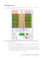
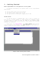
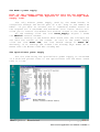
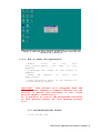
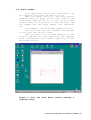
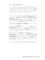
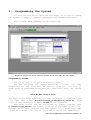
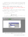
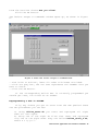
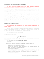
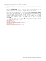
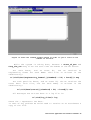
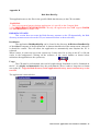
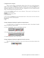
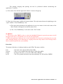
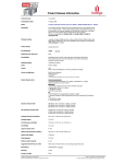
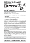
Rich Control
applications
User Manual
How to Operate the RICH Data
Acquisition System
N
W
E
S
By the
ICTP-INFN Microprocessor Laboratory
Crew
Version of 06/03
The manual is still under development. Hence, look for the last
version available.
Rich Control Applications User Manual- 7/18/2003 - 1
TABLE of CONTENTS
Introduction.
1.- Getting Started
Basic requirements for the operation of the system:
The Windows NT Server.
The BORA's power supply.
The optoisolator's power supply.
Chips in the system that require programming.
What happens at boot time.
2.- Rich Control Programs Set
Rich_Control application
Rich_Control_Server application
Event Viewer application
Rich Noise/Thresholds Viewer application
RichDataBackup application
3.- Programming the System
Programming DOLINA.
Checking if a DSP in DOLINA controlling a Chamber is alive.
Reprogramming a DSP in DOLINA.
Programming the FPGA and DSP in the BORAs.
Checking if a BORA is alive.
Checking if a chamber is alive.
Reprogramming the DSP and FPGA of a BORA.
4.- Operating the System
Measuring Pedestals and Noise of one Chamber.
Programming Thresholds in the BORAs.
Using the Threshold Generator.
Programming the RICH for Data Taking.
RICH data Back Up.
Appendices
Appendix A. Rich Low Voltage Power Supply: LOVE
Appendix B. Rich Data BackUp
Apendix C. RCSL (The Rich Control Scripting Language)
Rich Control Applications User Manual- 7/18/2003 - 2
Introduction:
Figure 1 shows the main components of the data acquisition.
The system consists:
Figure 1: the figure shows the architecture of the data acquisition system.
·
·
·
·
An NT Server.
The Dolina Board inserted into a PCI slot of the server.
Dolina has eight DSPs on board, one for each of the
chambers of the RICH.
Eight optoisolator boards whose mission is to de-couple
the ground of the chambers from that of the NT server.
192 BORA boards, 24 for each chamber. The BORAs of each
chamber are connected, forming a 1 Mbit/s network, with
the corresponding DSP in DOLINA.
Rich Control Applications User Manual- 7/18/2003 - 3
1.- Getting Started
Basic requirements for the operation of the system.
To operate successfully the system three initial requirements
must be met:
·
·
·
The NT server must be up and running.
The BORA's power supply must me ON;
The optoisolator board power supply must be ON.
The NT server
If the NT Server is powered OFF, turn it ON. It starts to
boot and at a certain moment it stops showing the Debugger's Menu
in the screen in front of you. To make it go forward press
control-D. It will then finish booting. “Rich” people will provide
Username and Password.
Click the icon Rich_Control (the Rich Control application)
that is placed in the Desktop. The "Rich Control" window opens up.
Figure 2 shows the Rich Control window.
Figure 2 shows the Rich_Control window.
Rich Control Applications User Manual- 7/18/2003 - 4
The BORA's power supply
Note: At the present moment what follows hold for the Chamber 0.
For the other chambers see Appendix A: Rich Low Voltage Power
Supply: LOVE.
The only Wiener power supply used by the BORA boards is
controlled through the RS-232 port of a PC. Long on the INFN's PC
#6227. If you have an account use it otherwise answer Cancel to
the request for a Username and Password. This latter choice will
allow you to control the Wiener but without access to the network.
On the Desktop click the icon Power_Supply. Figure 3 shows
the UEP6000 control window.
Before turning on the Wiener 6000 check that the voltages are
set with the values on the screen. To turn on the power supply
click the line Power OFF, the line should change to Power ON.
Obviously if at startup the screen line already says Power ON it
means that the Wiener 6000 was already ON.
The optoisolator power supply
For the time being the optoisolator power supply is contained
in a blue box placed close to the optoisolator and the RICH. Check
that it is ON.
Figure 3 shows the menu that controls the Wiener 6000 power supply.
Rich Control Applications User Manual- 7/18/2003 - 5
Chips in the system that require programming.
We'll describe what goes on at boot time in order to provide
some meaning to the actions that will be describe in the remainder
of this document.
The RICH Data Acquisition System attains its flexibility by the
incorporation of several programmable chips. Consequently we need
to program them in order to make the system function at all.
The programmable elements of the system are:
·
·
·
The eight DSPs in Dolina.
The 24 DSPs in each of the 8 chambers, for a total of 192
DSPs.
Each BORA board has a Virtex Field Programmable Gate Array
(FPGA), for a total of 192 FPGAs.
What happens at boot time.
When the system receives either a hardware or software reset
all the DSPs of the system boot from the corresponding EEPROM.
At boot time the eight Dolina DSPs load and executes from the
corresponding EPROMs, a routine that makes the DSP wait for a
program to be loaded by the PC. Hence Dolina becomes completely
flexible but we need to provide DOLINA with eight programs for its
DSPs.
At boot time the 192 BORA DSPs load a program from theirs
EEPROMs that allows each of them to read a switch header on the
board where his ID has been set. It also sets all parameters of
the network such as the number of slots in the Time Division
Multiplexed (TDM) network, the number of bits in the slot, etc.
Then the DSP waits for a program or simple command from the
Network.
At boot time the 192 FPGAs just wait to be programmed by the
corresponding DSP on the BORA board. The FPGAs need to be
programmed to perform any function whatsoever.
Rich Control Applications User Manual- 7/18/2003 - 6
2.- Rich Control Programs Set
In
chapter
1,
it
was
described
the
architecture of the data acquisition system. This
chapter
introduces the set of programs that the
Rich operator needs to program, calibrate and
supervise the readout system.
In the Rich Barrack there are two dedicated
PC’s to operate the Rich: richctrl computer and
richsrv computer(standing for RICH server). The
first computer has the Dolina board and allows the
control and supervision of the Rich, and the
second one stores the acquired data. Both PC’s are
interconnected through a dedicated Ethernet link.
The front-end electronics, (Bora boards) are
in the experimental area. Eigth serials networks
connect Dolina with 192 Bora boards, see figure 4.
The applications that form the Rich Control
Programs set are:
Dedicated link
Dolina Board
Rich Control application
Rich Control Server application
Rich Event Viewer application
Rich Noise/Thresholds Viewer application
RichDataBackup application
Rich Chambers
richctrl
computer
richsrv
computer
Experimental area (Rich front-end Electronics)
Rich barrack
12345-
Figure 4 View of the organization of the control computers and frontend electronic of the Rich
Rich Control Applications User Manual- 7/18/2003 - 7
The first four programs are executed on the
richctrl computer (richctrl.cern.ch).
The last above mentioned application will be
running in the richsrv computer.
2.1- Rich_Control Application:
This program is the main application and
performs the communication between the user and
the Rich control Data Acquisition System.
This application allows the user to send
commands and programs through the Rich DSP network
(see chapter I) to the Bora boards and eventually
to the CATCHes using the fibers, offering the
complete control of the system by the user.
One view of the principal Rich Control
Windows is shown on the figure 2,
chapter 1
(Rich_Control window).
This application performs two fundamental set
of tasks:
a) The communication with all the devices
available in the system (see [5]). In this set of
tasks the program manages several kinds of
internal
packets
[3]
engineering
frames,
calibration/noise, thresholds, events, commands,
programs and generates several kinds of files
depending on data.
b) The communication between the user and the
data acquisition system provided by the windows
application (GUI), the script editor and the main
view application.
This set of tasks is explained in the
following chapters of this manual.
There is a scripting language implemented in
the core of the Rich_Control application.
The RCSL (RICH Control Scripting Language),
is a script language that follows the philosophy
of Tcl/Tk or Pearl and easily allows the creation
of complex task using a set of atomic commands.
Rich Control Applications User Manual- 7/18/2003 - 8
This language is formed by statements. Its
syntax and complete set of instructions is
explained in the appendix C “The RCSL (RICH
Control Scripting Language)”.
2.1.1
- How to Start the application:
- Double Click on the icon Rich_control you have
on the desktop of the richctrl computer.
Important: Only one instance of the Rich_control
application can be active at the time. If there is
another instance of this process running the
MessageBox will appear indicating this error and
this instance of the application will be closed.
2.1.2- Configuration File:
The Rich control application performs several
controls during its execution. In order to
coordinate the processes intercommunication, the
Rich Acquisition status and the physical drives
where the data is saved, there are five parameters
to set and save inside the configuration file
before the Rich Control execution starts.
If you open the config.txt file h:\rich\exe
folder you will see a series of lines that look
like:
Setdrive h
SetSystemPath c:\\winnt\\system32
SetRemotedrive j
SetRunNumber 102
Running = N
Important: The configuration file was saved by the
Rich Software developers, so you can change one or
more lines if it is absolutely necessary.
The meaning of each line is explained in the
description of each specific topic.
Rich Control Applications User Manual- 7/18/2003 - 9
2.1.3- Log Files:
At
every
start
of
the
Rich
Control
application a Log File is generated, where it is
possible to find the command execution sequence
and the error messages.
The Logs files are in the Rich\Log_files
folder on the richctrl computer.
If you open that folder you will see a series
of
file
names
that
look
like:
2002.03.21_17.07.59.log
First you find the date followed by an underscore
character and then the time, with extension log.
2.2- Rich_Control_Server application:
This process allows the control of the Rich
Data Acquisition from the Control Room. So it is
possible to send some commands from the Control
room in order to Start and Stop the acquisition,
for instance.
The
client/server
model
in
network
programming is used. A client application has to
make a request to be recognized by another
computer in the network. This second computer has
a server application running that fulfills the
client’s request and returns the information. In
our case the Richctrl Computer (in the Rich
Barrack) will have the Rich_Control_server process
(socket server) running continuously, waiting
(listening) for a command, while the client
process will be running on the computer of the
Control Room, sending a request each time it is
necessary. This server process locally exchanges
messages with the Rich Control application which,
in its turn, sends the commands to the Bora’s
DSPs.
For more details see [6].
Rich Control Applications User Manual- 7/18/2003 - 10
Figure 4 show the Rich_control Server window starting and
opening the connection.
2.2.1- How to Start the application
- Double
Click
on
the
icon
Rich_control_server
you
have
on
the
desktop.
- A Message Box shown on the figure 4
appears.
- Press
OK
button
to
start
the
application.
- Press OK button again if the connection
is successfully opened.
Important: This windows will disappear when the
client process requests a command remotely and the
process is active and available to the client
process request continuously.
It is possible to control the background execution
of this process seeing the task manager process
list.
2.3- Noise/Thresholds Viewer
To be filled soon
Rich Control Applications User Manual- 7/18/2003 - 11
2.4- Event Viewer
This application allows the visualization of
the complete Rich event arrived to the PC.
When the events arrive to the Rich Control
computer they are saved on the local disk by the
RichControl application in a file in the event
folder, where it is possible to find the date, the
run number and the burst number with extension
evt.
For example: 2002.02.15_RUN_0_BURST_2430.evt
This file has only two columns: the address
of the pixel and the hit value.
Then an event file is saved remotely on the
richsrv computer for each Bora with the complete
event information: event header, quantity of hits
and event trailer.
Figure 5 show the Rich Event Viewer showing a
complete event.
Rich Control Applications User Manual- 7/18/2003 - 12
2.5 - RICH data Back Up.
Due to the rate of data arriving from the
data acquisition sytem being around 3,5 GBytes per
day, the events are saved remotely on the another
computer in the Rich Barrack called richsrv
(richsrv.cern.ch). There is an application called
RichDataBackup running continuously taking the
data and saving it on the rewritable CD.
The configuration of this application is set by
the config file located in the Rich\exe folder.
The lines Setdrive <drive> and SetRemoteDrive
<drive>
in
the
configuration
file
Rich\exe\config.txt specify the location of the
RICH folder in the local computer richctrl and in
the remote machine richsrv respectively.
There are mainly two configurations in which we
can work with richctrl and richsrv:
1) Working with richctrl only.
The drive specified in the lines Setdrive and
SetRemoteDrive of the configuration file must be
the same and must belong to richctrl. In this case
everything will be saved in richctrl and no Data
Back Up is foreseen.
2) Working with both richsrv and richctrl.
The
drives
specified
in
Setdrive
and
SetRemoteDrive must belong to richctrl and richsrv
respectively. The remote drive specified in
SetRemoteDrive must be mapped onto richctrl. In
this case only Event and Engineering Frame files
will be saved on the remote drive and Data Back Up
is possible.
To learn on how to install and operate the Rich
Data Back Up software application see Appendix B
Rich Control Applications User Manual- 7/18/2003 - 13
3.- Programming the System
In this section we'll describe the steps to follow to setup
the system in order to measure pedestals and standard deviation.
While inside Rich_Control do the following:
Figure 4 shows the Rich Control window with the Open Do file menu.
Programming DOLINA
The first step is to program Dolina's DSPs.
The DSP programs are loaded executing a script file that
simplifies all the procedure. We need to find the *.do file to
send. This is performed using the pull down menu send, see figure
2:
Send è Run Script file
The open file window opens up as shown in figure 4. Type into the
file name text window H:\rich\script_files\dolina_start.do. Then
click on the OK button or press enter on the keyboard.
The same action can be activated by simply logging into
H:\rich\script_files\ and double clicking in the name of the file.
Another option that produces the same effect is to darken the name
of the file within the list of files and clicking the OPEN button.
Rich Control Applications User Manual- 7/18/2003 - 14
The script file will execute the many instructions contained
in the do file. While it executes the operation the software shows
messages on the screen. Look for possible error messages since
they express the fact that some of the procedures were not
correctly executed.
Checking if a DSP in DOLINA controlling a Chamber is alive.
We assume that at this point you have already programmed all
eight DSPs (Chambers) of Dolina.
If you want to check if the DSPs have been properly
programmed there is a command whose action is similar to Ping on
the network, that allows you to check if a DSP of Dolina,
controlling a chamber, is ready for operation.
The procedure is the following:
Using the Menu bar open
Send à Send_comm
The "Command" window opens up asking for the command to send
to the system. The screen is shown in figure 5.
Figure 5 shows the send è send_comm. With the combo box opened.
Rich Control Applications User Manual- 7/18/2003 - 15
From the text box choose Are you alive?
Click the OK button.
The "Select Target to Command" window opens up, as shown in figure
6.
Figure 6 shows the select target to Command menu.
- Tick "talk to Dolina", leave all other tick boxes un-ticked.
- Click one grey bar, the one that represents the chamber that you
want to check.
- Click the OK button.
If the corresponding Dolina DSP is correctly programmed you
should get "Yes, I'm alive" as an answer.
Reprogramming a DSP in DOLINA.
If by any chance you get an error from the DSP queried there
are two procedures you can use.
a) Using dolina_start.do you reset and reprogram all eight
DSPs all over again.
b) Using one of the eight do files that reset and reprogram
only one of the eight DSPs. They are called Dolina_Start_x.do,
where x = 0,1,2…7.
Rich Control Applications User Manual- 7/18/2003 - 16
Programming the FPGA and DSP in the BORAs.
At this point we assume that you have already
programmed the DSPs, Chamber controllers in Dolina.
correctly
We now need to program the FPGA in each BORA and load in the
DSP the program to execute the FPGA programming procedure in the
corresponding BORA DSP.
To program the FPGAs and DSPs of the BORAs there are ready
made do files called chamberX.do, where X=0,1,2,7 is the number of
the chamber to be programmed. These files are found in the folder
H:\rich\script_files\. When we program a chamber we understand
that we are programming all 24 BORA DSPs and FPGAs of the chamber.
Execute the do file following the procedure described in
"Programming Dolina". Look at the messages shown on the screen
while the do file executes. If you see an error message please
phone us.
Checking if a BORA is alive.
We assume that at this point you have already programmed all
needed BORAs.
If you want to check if a BORA has been properly programmed
there is a command similar to Ping for a network that allows you
to check if the DSP in the BORA is up and running.
The procedure is the following:
Using the Menu bar open
Send à Send_comm
The "Command" window opens up asking for the command to send to
the system.
For the text box choose Are you Alive?
Click OK.
Then, the "Select Target to Command" window opens up
-
Leave all tick boxes un-ticked.
Click the grey bar that represents the chamber where the
BORA you want to check resides.
Click the OK button.
The Dialog window opens up showing the 24 BORAs of the
selected chamber. Click a BORA grey bar. Click OK and the
window closes returning to "Select target to command".
Click the OK button.
Rich Control Applications User Manual- 7/18/2003 - 17
If the DSP of the BORA is correctly programmed you should get
"Yes, I'm alive" as an answer.
Checking if a chamber is alive.
This can be performed in two ways:
a) Using the Dialog window “Select Target to command”
- Choose from the combo box the command Alive?, as shown in
figure 5, and then click on the OK button.
- After the OK the window Select Target to Command opens up
as shown in figure 7. Tick the box named Select a Complete
Chamber, then click on the grey bar that represents the whole
chamber. Click on the OK button. This action sends the command to
all 24 BORAs of the chamber.
b) Running a script file
To check if a complete chamber is alive, you can run the
corresponding
script
file
Alive_ch*.do
in
the
folder
H:\rich\script_files\Alive_all_chambers. The procedure to run a
script file was explained before, see “Programming DOLINA”.
Figure 7 shows the window from which we choose the chamber to send a command.
Rich Control Applications User Manual- 7/18/2003 - 18
Reprogramming the DSP and FPGA of a BORA.
Assume one BORA is dead, hence not alive. We must first reset
the BORA.
a)Using chamberX.do script file you reset and reprogram all 24
BORA’s DSPs and the FPGAs of chamber X all over again.
b) There are 192 do files in the folder H:\rich\script_files\
that reset and reprogram the DSP and the FPGA corresponding to
only one BORA of the system. Assume that X = 0,1,2.., 7 is the
chamber number and that Y = 0,1,…23 is the number of the BORA
within the chamber. Then, the do file to use is called
ScX_Y.do.
If you open one of these do files you will see a series
of commands that look like:
Send_comm
Send_comm
Send_data
Send_data
Send_comm
Send_comm
Send_data
Reset -X,Y
PC_Start -X,Y
\rich\dsp_programs\bora_fpga_v1_128.stk -X,Y -s
\rich\bit_stream_files\fpga_5.rbt -X,Y
Reset -X,Y
PC_Start -X,Y
\rich\dsp_programs\bora_spill.stk -X,Y
Rich Control Applications User Manual- 7/18/2003 - 19
4.- Operating the System
Measuring Pedestals and Noise.
We assume that the BORAs to be measured and the correspondent
DSPs of Dolina have already been correctly programmed.
We can measure Pedestals and noise in only one BORA through
commands from the Rich_Control menu, or in many BORAS by running
specific script files.
1) Only one BORA.
Open using the pulldown Menu of Rich_Control
Send à Channel_Test
The window Channel Test opens as shown in figure 8.
Figure 8 shows the Channel Test window that controls the measurement of
Pedestals and Noise of all pixels of one BORA board.
Rich Control Applications User Manual- 7/18/2003 - 20
-
Type the number of samples, the number that determines the
statistics of the measurement, in the text box Number of
Samples (powers of 2, between 4 and 2048).
Type the chamber number in decimal in the text box Chamber.
Type the BORA number in decimal in the text box Bora.
Tick the Noise Analysis box.
Tick the Application Read / Dolitest Enable box. Don't tick
any other box.
Click Send.
You will see an Error window opening up. Look at the file in
the window since the result of the measurement is in that file, so
write the name and path of the file. The results, pedestals and
noise, are in that file.
After you have written down the name and path of the file, click
OK.
The folders, where the resulting files with pedestals and
noise are written, are named according to the following
convention. Remember that there are 192 BORAs in the system.
In chamber 0 BORAs are numbered from 0 to 23. The results are
written by the application in the folder:
H:\rich\data\calibration\bora#; where bora# = 0 to 23
For the chambers 1-7 BORAs are still numbered from 0 to 23 within
the chamber, but to avoid writing over the previous files the
folders are called:
H:\rich\data\calibration\(chamber#*24+bora#);
Where: chamber# = 0 to 7 and bora# = 0 to 23
For example, if you measured pedestals and noise of the BORA board
number 3 of chamber 4, the calibration file can be found in:
H:\rich\data\calibration\99\
2) Many BORAs.
Open using the pulldown Menu of Rich_Control
Send à Run Script file
a script file located at
H:\Rich\Script_files\Channel_test_2048_samples
Rich Control Applications User Manual- 7/18/2003 - 21
The following script files are available:
Channel_test_chX.do: measures noise in chamber X (0,1,...,7).
Channel_test_all_chambers.do: measures noise in all 192 BORAs (it
takes about five minutes).
Programming Thresholds in the BORAs.
We assume that at the DSPs of Dolina and the BORAs have
already been correctly programmed. Until this date the system must
be idle, that is not taking data. At boot time the thresholds
are set all equal to zero.
The threshold editor will also allow overwriting the results
of a uniform procedure by adding masking possibilities. The mask
will allow setting arbitrarily the threshold to its maximum value
to, for instance, cancel the data from produced by the beam halo.
Here we describe what we can do now and here.
For setting thresholds we can work at BORA or CHAMBER level.
We can also generate thresholds at RICH level by using the
Threshold Generator.
1) Only one BORA.
There are three methods to generate and load thresholds into
a single BORA:
a) The first method allows setting all thresholds to the same
value.
b) The second method allows sending a *.trh file. The *.trh
files are ASCII and consequently the operator can manually
edit it using any standard word processor such as Wordpad or
Notepad, etc.
c) The third method allows creating a threshold file using the
calibration file of a BORA. The thresholds are uniformly set,
for each channel of the BORA, using the following operation:
Ti = Pi + (z * si)
Rich Control Applications User Manual- 7/18/2003 - 22
Figure 9 shows the Threshold window used for the three different methods to set
the thresholds for one BORA.
Where Ti, Pi, si are the threshold, pedestal and noise standard
deviation of the channel number i of the BORA. Z instead is an
arbitrary constant chosen by the operator.
For all three methods you open RICH_Control first, then using
the mouse you:
Thresholds è Set Thresholds
The Thresholds windows open up, as shown in figure 9.
Rich Control Applications User Manual- 7/18/2003 - 23
Also for the three methods we have to choose the target BORA
by filling in Chamber and BORA text boxes.
For method (a) we fill the text box Threshold = with a
number between 0-1023. We then click the OK button and the
thresholds are sent to the target BORA.
For method (b) we click the Select ASCII file. We select
from the menu a Tab separated ASCII file. We then click the
OK button and the thresholds are sent to the target BORA.
Figure 10 shows a portion of such an ASCII file. The file can
be edited by hand using any text processor. The first column
is the channel number and the second the threshold value that
must be in the range 0 to 1023.
For method (c) we fill the blank text box under Set
Threshold from a calibration file. We click the Select
Calibration file button, afterwards selecting a file from the
chosen subdirectory. We then click the OK button and the
thresholds are sent to the target BORA.
.
.
14
15
16
17
18
19
20
21
22
23
24
1023
1023
1023
1023
1023
1023
1023
1023
1023
1023
1101
.
.
Figure 10 shows a portion of a *.trh ASCII file. The first column is the
channel number and the second column is the value of the threshold. The file
can be edited by hand using any text processor.
Rich Control Applications User Manual- 7/18/2003 - 24
2) Complete chamber.
To load thresholds to a complete chamber
a) Enter the chamber number (0 to 7)
b) Click check button: “Send the threshold values to the all
chamber”
c) Click Ok.
NOTE: With this procedure the application loads the latest *.trh
files (not the *.thr files!) found in the corresponding BORA
folders. See below on how to generate these *.trh files.
3) The complete RICH.
To send the thresholds to the complete Rich.
For this method you open RICH_Control first, then using the
mouse you:
Thresholds è Send Thresholds to all the Rich
NOTE: With this procedure the application loads the latest *.trh
files (not the *.thr files!) found in the corresponding BORA
folders, and the thresholds will be sent chamber by chamber as you
can see in the main application window. See below on how to
generate these *.trh files.
Rich Control Applications User Manual- 7/18/2003 - 25
Using the Threshold Generator
This can be used to generate thresholds files for all BORAs
of the RICH, using as input the latest calibration files (*.tri)
found in the corresponding BORA folders. These threshold files
will be generated according to the formula Ti = Pi + (z * si) as
explained before.
Open using the pulldown Menu of Rich_Control
Thresholds à ThresholdsGenerator
The window Threshold Generator opens as shown in figure 11.
Figure 11 shows the Threshold generator window.
Rich Control Applications User Manual- 7/18/2003 - 26
1) Enter the sigma coefficient z in the box “Multiplier (N)”
2) Check the button “Load all” and click the button “Load file”.
3) When the “load file” button is clicked, a dialog box opens.
Select the “calibration format” in the “File of Type” field.
Then
browse
to
find
any
calibration
file
in:
H:\Rich\Data\Calibration\0\*.tri and select any calibration
file. The application will automatically select (independently
of your selection) the latest calibration files of all 192
BORAs found in the corresponding folders.
4) Click on button “Save thres”, then you will be prompted to
enter the output file name. Thresholds files of type *.trh will
be saved in the BORA folders.
Channel Masking
Setting the threshold to the highest value can mask any
channel. To do this one must know the absolute coordinates of the
channel at RICH level. These values can then be stored in a mask
file with .msk extension. This file can be generated by either
using any ascii editor or the mask part of the threshold
generator. The threshold value in the mask file overwrites the
existing threshold values at the specified location creating a new
threshold file.
1)
2)
3)
4)
5)
a)The following steps show how to generate the mask file:
Enter the X,Y coordinates in their respective input boxes.
Enter the new threshold value (e.g. 1023) in the “New Value”
box. To commit the change click on “Add Mask” button.
The “Remove Mask” button can be used to remove any mask from
the mask file corresponding to the X,Y coordinates.
Steps 1 to 3 can be performed for all channels of interest.
Save the mask file by using “Save Mask” or “Save (Mask) As”
button.
b) Applying Mask: To generate a new threshold file from the
mask file:
1)
Load the RICH threshold file from the
RICH\Data\threshold_values\RICH directory.
2)
Load the mask file.
3)
Click “Apply Mask to thres” button. This will generate a
new threshold file in each BORA directory and the RICH
directory.
Rich Control Applications User Manual- 7/18/2003 - 27
Programming the RICH for Data Taking
We assume that all the DSPs of Dolina and the BORAs have
already been correctly programmed and the thresholds with
threshold values such as to obey the rule that all events should
have occupancy below 20%. The violation of such a rule will
produce the overflow of the FIFO controlling the fiber.
Also, the trigger rate should be below 70 ktrigger/s. The
violation of this rule will produce an overflow of the Cypress
FIFOs.
We also assume that there are event triggers as well as Start
of Burst (SOB) and End of Burst (EOB) triggers coming from the
TCS.
Three commands are needed for data taking:
a) Sync_catchs, b) start_of_Run, and c) Stop_the_run.
a) Sync_CATHes: CATCHes Synchronization
Before any data taking we must be sure that the BORA-CATCH
link is synchronized. There is a specific command for this:
Sync_CATHes. This command must be issued after any RICH-CATCH has
been rebooted. In case we suspect there is no RICH-CATCH
synchronization we can use this command before any data taking.
To issue Sync_CATHes command to the whole RICH use the mouse
to select:
Send è Sync_CATHes
b) Start of Run
Using the mouse select
Run è Start of Run
The Commands window opens as shown in figure 12. This command
will be automatically sent to the whole RICH. Now we are ready to
accept triggers and acquire data. After Start_of_Run is issued you
will see the red button “RUNNING” highlighted.
c) Stopping data taking: Stop the RUN
Stopping data
as described for
command instead of
will see the green
taking is very simple. Execute the same steps
the Start_of_Run, but choosing Stop_the_run
Start_of_Run. After Stop_the_RUN is issued you
button “NOT RUNNING” highlighted.
Rich Control Applications User Manual- 7/18/2003 - 28
Figure 12 shows the command window opened in order to give a start of run
command to the Rich.
While the system is taking data, between a Start_of_Run and
Stop_the_run many files are sent from the BORAs to the NT server.
For each burst, and as event #1, the PC receives an
engineering frame for each BORA. This file is written in the
subdirectory:
H:\rich\data\engineering_frames\[(chamber# * 24) + bora#]\*.eng
For each particle burst, and as event #3, the PC receives the
event data. This file, one for each BORA, is written in the
subdirectory:
H:\rich\data\events\[(chamber# * 24) + bora#]\*.evt
All messages are written down in a log file in:
H:\rich\log_files\*.log
where the * represents the date.
In case of any problem we would need to receive as an attachment a
copy of the file.
Rich Control Applications User Manual- 7/18/2003 - 29
Data taking for a chamber: The commands explained above could be
issued to a single Chamber following the procedure explained for
the Command Alive?. In this case the colored buttons (“RUNNING”,
“NOT RUNNING”) will not work and will be up to you to know the
state of the chamber, this is because “RUNNING”, “NOT RUNNING”
buttons this was thought for all the RICH.
RICH data Back Up.
During a normal run the RICH generates many data in many small
files. In order not to saturate and slow the NT server machine
with a huge system file it is possible to save and eventually back
up data in a remote machine from now on called richsrv (standing
for RICH server).
On richsrv will be a specific application, RichDataBakUp, to
back up data from the hard disk to rewritable CDs. The lines
Setdrive <drive> and SetRemoteDrive <drive> in the configuration
file Rich\exe\config.txt specify the location of the RICH folder
in the local PC richctrl and in the remote machine richsrv
respectively.
There are mainly two configurations in which we can work with
richctrl and richsrv:
3) Working with richctrl only.
The drive specified in the lines Setdrive and SetRemoteDrive of
the configuration file must be the same and must belong to
richctrl. In this case everything will be saved in richctrl and no
Data Back Up is foreseen.
4) Working with both richsrv and richctrl.
The drives specified in Setdrive and SetRemoteDrive must
belong to richctrl and richsrv respectively. The remote drive
specified in SetRemoteDrive must be mapped onto richctrl. In this
case only Event and Engineering Frame files will be saved in the
remote drive and Data Back Up is possible.
To learn on how to install and operate the Rich Data Back Up
software application see Appendix B
Rich Control Applications User Manual- 7/18/2003 - 30
Appendix A.
Rich Low Voltage Power Supply: LOVE
To be filled soon
Rich Control Applications User Manual- 7/18/2003 - 31
Appendix B.
Rich Data BackUp
This application moves the files in the specified Rich data directory to the CD rewritable.
WARNING:
1. This is not a general purpose backup application, it is specific to the Compass Rich.
2. Use PREFORMATED REWRITABLE CDs only, the application does NOT support WORM
or UNFORMATED rewritable CDs.
IMPORTANT NOTE:
This version does not create the Rich directory structure on the CD dynamically, the Rich
directory structure must exist on the CD (see instruction below on how to do this)
Installation
The application RichDataBakUp can be found in the directory d:\Rich\exe\DataBackUp
of the richsvr computer of the Rich Barrack. A shortcut should exist in the startup menu, otherwise
it should be created. This will allow the application to automatically start anytime the PC is
rebooted.
When it starts, it creates an icon in the system tray. It stays there for as long as the PC is ON and
works in the background. Clicking on the minimize or the cancel buttons as shown below
minimizes the application to the system tray.
Usage:
The CD must be preformatted, this can be bought already formatted or can be formatted on
the PC. It is highly recommended to buy the preformatted CDs as it takes a long time to format
one on the PC. Copy the Rich directory in the application directory (Rich\exe\DataBackUp) to the
new CD.
The application is shown below
Rich Control Applications User Manual- 7/18/2003 - 32
Configuration file (config.ini)
When it starts running, it automatically backup all the files in the specified directories,
which it loads from the config.ini file. Hence the first thing to do is setup the config.ini file. A
sample can be found in the application directory. It must reside in the same directory as the
application. Modify this for your specific needs. The configuration file can be modified with any
editor. The followings must be specified in the file:
1) The section [srcdirs] specifies the source directories. These must be the full path of the
directories to be backed up ie
[srcdirs]
H:\Rich\data\Engineering_frames
H:\Rich\data\Events
2) The second part [dstndrives] means the destination drives. These must be the drive letters for
the CD writers and are comma separated.
[dstndrives]
e,f,g,h
Starting, Stopping and Quitting the application using the buttons
As mentioned above, the application starts automatically with the “Start Backup” disabled
and the “Stop BackUp” button enabled.
1) Click on “Stop BackUp” button to stop backing up the data.
2.) To resume the backup, click on “Start BackUp” button.
3) To quit the application, click on “Exit” button
Starting, Stopping and Quiting the application from the system tray
When the application is minimized, it stays on the system tray and continue running in the
background.
Rich Control Applications User Manual- 7/18/2003 - 33
The starting, stopping and quitting can also be performed without maximizing the
application. To do this,
1) Click on the icon with the right mouse button. A menu will pop up.
2) Select any of the menus with the left mouse button. The only menus that need explaining are the
“open” and the “Close DataBackup” ones.
a) The open menu maximizes the application in case one wants to look at the status of the
disks. Double clicking the icon has the same effect.
b) The “Close DataBackup” is the same as the “Exit” button.
WARNING:
1. The access to the CDRW is slow, so after the StopBackUP button is pressed you must wait till
the ligth of the drive is off and then you can close the application.
2. When the application finds an error on the destination CD, instead of performing the eject task
and eventually passing to the following cd, copying of the files stops and an error message shows
that is needed to perform the eject manually.
Drive Info
The status of the drives is indicated with text and LEDs. The status could be:
Full
No disk
Empty
In use
- The disk is full, and the LED will be RED.
- There is no rewritable disk in the drive, LED will be RED.
- No data on the CD, i.e. new CD, LED will be GREEN.
- The CD is partially full and is the current backup CD, LED will be GREEN.
Rich Control Applications User Manual- 7/18/2003 - 34
Apendix C
RCSL (The Rich Control Scripting Language)
This script language is formed by commands that provide the
possibility to send and receive data and program packets we
have defined in[3,4]. These commands permit the information
exchange and the communication between the user and the Bora
boards network.
General Syntax of the statements:
Statement [<command>/<data>] <source> to <destination>
[<command>/<data>] Selects a command or a program (DSP or FPGA
program) to be sent.
<source> Specifies the drive, the directory and the file
containing the program. In case of the command you can simply send
the specific command putting the destination.
<destination> Is used to describe the target. The syntax is the
following:
-chamber_number,bora_number
If you need to communicate with a Dolina DSP only, just
put the Dolina DSP number without specifying the Bora’s
DSP number.
Statements
The following statements are defined:
Send_comm
This statement allows to send a command.
Send_data
This statement allows to send a DSP or FPGA programs.
End.
Is to indicate the end of the Script file.
Rich Control Applications User Manual- 7/18/2003 - 35
Example:
Send_comm PC_Start
-6
(Sends a PC_Start command to the DSP number 6 to start the Dolina DSP loader.)
A Script file could look like it is shown on the figure 1, the
explanation of the commands is included.
Send_comm PC_Start –0
(This command implies the feedback message from the Dolina DSP number 0
–Loader request-)
Send_data \rich\DSP_programs\prog1.stk –0
(The application checks if the Dolina DSP sends back -Loader
Acknowledge-. If there was an error the application gives an error
message).
Send_comm Alive –0
(The application checks for the -I’m Alive- message).
Send_comm
Send_data
Send_comm
End.
Figure
PC_Start –1
prog1.stk –1
Alive -1
1: A script file programming the Dolina DSPs number 0 and 1.
Command List:
This is a list of the commands with a short description, for more
details see [3] and [4].
PC_Start
Alive
Reset
Channel Test
Start of Run
Stop of Run
Catch_Sync
Reset_FPGA-GASS
(Starts the DSP loader)
(Checks if the DSP program is working properly)
(Sends a software reset to the DSP)
(This command has a special format, explained below)
(Starts data acquisition)
(Stops data acquisition)
(This command is sent through the Boras DSP's network in order
to synchronize the Rich and the Catches)
(Sends a reset to the gassiplexes of the FPGA)
Rich Control Applications User Manual- 7/18/2003 - 36
Channel Test Command
Command format (break space separates parameters)
Send_comm Channel_test D/A_pulse Trigger_Delay #_Samples Op_Type
Data_Format App/Dolitest Destination
Where:
All the numbers below are decimal.
D/A_pulse
- the amplitude of the stimulus pulse. Can take the
value from 0 up to 255;
Trigger_Delay
#_Samples
- can take the value from 0 up to 2047 ;
- can take the value power of 2 from 2 up to 2048;
Op_Type
Data_Format
- defines DAQ mode, 0=Noise, 1=Calibration.
- defines the format of the incoming data.
0=(Average and Sigma), 1=Raw_data; (Debugging
option).
Must be set to 0.
- Must be set to 0. (Debugging option).
-chamber,bora identification number, using the way
described before in the general syntax description.
App/Dolitest
Destination
Examples:
Send_comm Channel_test 0 0 32 0 1 0 –3,11
Here we read 32 samples from chamber 3 bora 11 acquiring
noise .
Rich Control Applications User Manual- 7/18/2003 - 37
Send_comm Channel_test 0 0 2048 0 0 0 -6,0
Send_comm Channel_test 0 0 2048 0 0 0 -6,1
Send_comm Channel_test 0 0 2048 0 0 0 -6,2
Send_comm Channel_test 0 0 2048 0 0 0 -6,3
Send_comm Channel_test 0 0 2048 0 0 0 -6,4
Send_comm Channel_test 0 0 2048 0 0 0 -6,5
Send_comm Channel_test 0 0 2048 0 0 0 -6,6
Send_comm Channel_test 0 0 2048 0 0 0 -6,7
Send_comm Channel_test 0 0 2048 0 0 0 -6,8
Send_comm Channel_test 0 0 2048 0 0 0 -6,9
Send_comm Channel_test 0 0 2048 0 0 0 -6,10
Send_comm Channel_test 0 0 2048 0 0 0 -6,11
End.
--If it’s necessary include some comments you can do at end --of
the Script file like in this case.
The figure 2: The Noise measurement of the half of chamber number 6 with
2048 samples.
Rich Control Applications User Manual- 7/18/2003 - 38
[1] Colavita A., “All you wanted to know about decoding the RICH-1
but were afraid to ask”.
[2] Baum et al., BORA: A front end board, with local intelligence,
for the RICH detector of the COMPASS collaboration, Nucl. Instr.
Meth. A 433 (1999) 426.
[3] Crespo M., “COMPASS RICH-1 Read Out System”
Network Packets . ICTP-INFN, Microprocessor Lab.
[4] Crespo M., “COMPASS
Microprocessor Lab.
RICH-1
Read
Out
–
System”.
Apendix
A
ICTP-INFN,
[5] Diaz V, “Rich Control application Fundamentals Documentation”.
ICTP-INFN, Microprocessor Lab.
[6] Diaz V, “Rich Control application
ICTP-INFN, Microprocessor Lab.
from the Control room”.
Rich Control Applications User Manual- 7/18/2003 - 39