1
US008032776B2
(12) Ulllted States Patent
(10) Patent N0.:
Merkin
US 8,032,776 B2
(45) Date of Patent:
Oct. 4, 2011
‘54) SYSTEM FOR MAXIMIZING SERVER
38358383533 21
13833 ?h?ng e‘ 31"
UTILIZATION IN A RESOURCE
CONSTRAINED ENVIRONMENT
2003/0028642 A1
2003/0046393 A1
2/2003 Agarwal et a1.
3/2003 Mueller et al.
(75)
.
Inventor‘
-
'
2003/0046396 A1
3g?“ E‘ Merkm’ Holly Spnngs’ NC
0
3/2003
Filed:
Richter et a1.
2003/0065986 A1
4/2003 Fraenkel et a1.
g?lllpner et a1~
l
O
Corporatlon’ Armonk’ NY (Us)
Subject to any disclaimer, the term ofthis
2003/0135509 A1
2003/0217153 A1
patent is extended or adjusted under 35
2004/0003303 A1
2005/0055587 A1
2006/0184287 A1
1/2004 Oehleretal. ............... .. 713/300
3/2005 Lee
8/2006 Belady @1211. ............... .. 700/291
2006/0230299 A1
10/2006 Zaretsky et al. ............ .. 713/320
USC' 1540:’) by 325 days‘
(22)
713600
3/2003 O’Connor et al. .......... .. 713/300
-
Notice:
................ ..
2003/0056126 A1
(73) Assignee: International Business Machines
(*)
en et a .
Oct, 27 , 2008
(65)
7/2003 Davis et a1.
ll/2003 Rao et al.
Hitachi Ltd. White Paper on Power-Saving Modes of MicrosoftWin
dows Server 2008 SP2 on BladeSymphony 320. Revision 1.0.0. Sep.
Prior Publication Data
2009* Super Micro Computer Inc. SuperBlade User’s Manual.
Revision 1.0d. Nov. 3, 2010.*
Us 2009/0044036 A1
Feb' 12’ 2009
Hewlett-Packard Development Company. HP Power Capping and
HP Dynamic Power Capping for ProLiant servers. Technology brief.
2nd edition. Jan. 2011.*
Related US. Application Data
(63)
(51)
(52)
Continuation of application No. 11/209,870, ?led on
I
t N
S
hR ltf A
M ki datclFb.8,2008,
prge?g‘r ame earc
esu or aron er n
e e
Aug. 23, 2005, HOW Pal- NO- 7,461,274-
Of?ce Action from Chinese Patent Of?ce dated Jan. 29, 2010.
Int. Cl.
G06F 1/00
*
(200601)
US. Cl. ...... .. 713/324; 713/300; 713/320; 713/323;
I
(58)
I
I
713/340; 340/635
Field of Classi?cation Search ................ .. 713/300,
713/320, 323, 324, 340; 340/635
See application ?le for complete search history.
(56)
References Cited
' d b Y examiner
one
Primary Examiner * Matthew Spittle
(74) Attorney, Agent, or Firm * Winstead, PC.
(57)
ABSTRACT
A mechanism for controlling the hardware resources on a
blade server, and thereby limiting the power consumption of
the blade server is disclosed. The enforceable hardware
resources that are controlled include the base frequency of the
central processing unit (CPU) as well as power to individual
banks of physical memory, for example dual-inline memory
U.S. PATENT DOCUMENTS
5,522,042 A
5/1996 Fee et al.
6,516,350 B1
2/2003 Lumelsky et al.
6,674,756 B1
1/2004 Rao et al.
6,968,470 B2
7,051,215 B2 *
7,131,019 B2 *
7,237,130 B2
11/2005
running on the blade only have the allocated hardware
resources available to them. Deactivated hardware resources
Larson et al. ............... .. 713/340
5/2006 Zimmer et al. .
10/2006
6/2007
modules (DIMMs). The hardware resources are tuned in
dependence on actual server utilization such that applications
713/300
7,272,732 B2 *
9/2007
Lee ............ ..
Lee ........ ..
Farkas et al. ...... ..
713/340
713/323
713/320
7,349,828 B1 *
7,353,415 B2 *
3/2008 Ranganathan et al.
4/2008 Zaretsky et a1.
702/186
713/320
7,418,608 B2 *
8/2008
are powered off and are so ‘hidden’ from the operating system
when they are not required. In this manner, power consump
tion in the entire chassis can be managed such that all server
blades can be powered on and operate at higher steady-state
utilization. The utilization of the powered on resources in a
blade center is also improved.
5 Claims, 12 Drawing Sheets
Kumar et a1. ............... .. 713/320
1210
121 1
free
resources?
more
resources
2 Wm
1212
Blade:
calc. avaiiable PWR
Blade:
calc. requimd P
1254
PWR
available?
YES
1255
MM
Blade:
set CPU / DIMMs
US. Patent
0a. 4, 2011
Sheet 1 0f 12
mmain
Pm“Na0i5nm
ooP
om
US 8,032,776 B2
.F0_. . _ ~5262“:
US. Patent
Oct. 4 2011
Sheet 2 0f 12
E
2m305m
.UEu "E26?;
P0 1.52
&\\\\\\\\\\\\\‘
US. Patent
0a. 4, 2011
Sheet 4 0f 12
US 8,032,776 B2
w55m
“m05m
mwosm
.UEw
mma?a
mNain
US. Patent
0a. 4, 2011
Sheet 5 0f 12
US 8,032,776 B2
.GEm
w_.NMmwmnaosi?mn
com
cow
co?
o
25:C296592
%
US. Patent
0a. 4, 2011
Sheet 6 0f 12
US 8,032,776 B2
1...5:::.\:....
..
\IIIIn!I!‘InaiIn. .
\u:\I
OH
5
NH
MU
#P
my
D
0:
I.“
N:
m:
Sb
m5 m2;
0
com-
o
.QEm
US. Patent
0a. 4, 2011
Sheet 7 0f 12
US 8,032,776 B2
QZw-NE
NCO“.
gm
Sm
Epm2z - :902m.
FE
US. Patent
0a. 4, 2011
MPC-S1R MPC-S1R2
Sheet 8 0f 12
US 8,032,776 B2
FIGB
US. Patent
0a. 4, 2011
Sheet 9 0f 12
US 8,032,776 B2
PM2
US. Patent
0a. 4, 2011
Sheet 10 0f 12
US 8,032,776 B2
Chassis
Management
m
Module
MM
Processor
.LLQ
\
.
gowelr
upp y
141 Mg
llZ
Ventilator
/
\151 .152
L0
9'-
Chassis Slot U
\
serv'ce
Processor
Blade Server
1 3O
K
Jig
131
—--—
L_.____
DIMM
Application(s)
\
1_3_3
132\
Jig
129
Operating
System
FlesMon
Agent
Bios
137
CPU
138
1216
13.4.
——
_‘
FIG. 10
US. Patent
0a. 4, 2011
Sheet 11 0f 12
MM:
read PWR VPD
\ /1112
Blade:
get consumption
v /1113
MM:
allocate PWR
V /-1114
Blade:
set CPU / DlMMs
US 8,032,776 B2
US. Patent
0a. 4, 2011
Sheet 12 0f 12
Blade:
calc, required PWR
US 8,032,776 B2
Blade:
sale. available PWR
, /1'253
Blade:
request PWR
\ /1213
Blade:
set CPU / DIMMs
, /1214
Blade:
notify PWR
, /1215
_
MM:
MM
allocate PWR
de-allocate- PWR
I
v
/-1256
Blade:
-
set CPU / DlMMs
‘
L—-—~
PWR
OFF?
NQ
YES
V
(FINISH;
FIG. 12
1216
1202
US 8,032,776 B2
1
2
SYSTEM FOR MAXIMIZING SERVER
UTILIZATION IN A RESOURCE
CONSTRAINED ENVIRONMENT
values, Which can, in turn, force the common poWer supply to
shut doWn, causing other blade servers to be turned off.
Another risk is that any blade server exceeding its allocation
CROSS REFERENCE TO RELATED
APPLICATIONS
tures exceeding their critical thresholds.
Probably, one of the most pressing problems associated
can cause other blade servers to shutdoWn due to tempera
With servers is manageability and particularly manageability
as applied to chassis mounted servers. One aspect of manage
The present application is a continuation application of
US. patent application Ser. No. 11/209,870, Which Was ?led
on Aug. 23, 2005, Which is assigned to the assignee of the
ability Within this type of server relates to managing perfor
mance Within the constraints of the available resources. Well
knoWn in the art are management methods and their related
present invention. The present application claims priority
system architectures for maintaining a su?icient level of com
bene?ts to US. patent application Ser. No. 11/209,870.
puting poWer and aggregate data throughput in the face of
highly ?uctuating or deterministic service requests. Docu
TECHNICAL FIELD
mented application server resource management methods
aim to provide an optimum level of service for a given set of
resources, subject to a certain demand of computing poWer;
upon total utiliZation of available resources, the methods
The present invention relates in general to data processing
systems, and in particular, to communications netWork
devices referred to as blade servers.
generally assume that the processing poWer is expandable ad
BACKGROUND INFORMATION
20
in?nitum, thus demanding additional computing infrastruc
ture. HoWever, certain instrinsic resource constraints on any
given computing center location, such as available electrical
poWer, space, and cooling, are ?nite and thus effectively limit
The use of servers as devices Within communications net
Works is Well knoWn in the art. A server is equipment that
makes available ?le, database, printing, facsimile, communi
cations or other services to client terminals/stations With
25
signi?cant corporate resources and carry an economic impact
that goes Well beyond the cost of the core computing infra
structure. As blade server performance values, such as pro
cessor speeds and bus clock frequencies, have increased dra
access to the netWork the server serves. When the server
permits client/terminal station access to external communi
cations netWork it is sometimes knoWn as a gateWay. Servers
are available in different siZes, shapes and varieties. Servers
may be distributed throughout a netWork or they may be
concentrated in centraliZed data centers.
30
Advances in centralized data processing centers have
resulted in smaller form factors for server devices and an
increase in the density of processing units, thereby reducing
space requirements for computing infrastructure. One com
further expansion of that infrastructure. Projects for expand
ing or duplicating an existing computing center often require
35
matically, electrical poWer requirements Within a single blade
center have frequently reached constraining values, such that
it may not be unusual that insuf?cient electrical poWer is
available in a given chassis to simultaneously poWer on all
blade servers present in the chassis. Furthermore, since a
blade center chassis Will often be dimensioned for future
groWth and expansion, neWer, faster, poWer-hungry blade
mon form factor has been termed in the art a blade server,
comprising a device built for vertically inserting into a chassis
that can house multiple devices that share poWer and other
servers may need to be added to an existing chassis, Which
Would normally exceed the rated values for poWer consump
tion.
All of the aforementioned factors indicate that poWer
connections over a common backplane, i.e., a blade center.
Slim, hot sWappable blade servers ?t in a single chassis like
books in a bookshelfiand each is an independent server,
With its oWn processors, memory, storage, netWork control
resources are a critical element in the economic success of a
blade center. Therefore, a key aspect of manageability Within
this type of application server relates to allocating poWer
resources, Which has been solved by system architecture in
past con?gurations by forcing individual blade servers to
lers, operating system and applications. The blade server, also
referred to simply as a blade, slides into a bay in the chassis
and plugs into a mid- or backplane, sharing poWer, fans,
?oppy drives, sWitches, and ports With other blade servers.
The bene?ts of the blade server approach Will be readily
apparent to anyone tasked With running doWn hundreds of
shutdoWn, or not permitting additional blade servers to poWer
on. Clearly, a scenario Where not all blade servers in a chassis
may be poWered on is economically detrimental for the opera
cables strung through racks just to add and remove servers.
tor of the blade center.
The computing resources Within an individual blade server
With sWitches and poWer units shared, precious space is freed
upiand blade servers enable higher density With far greater
are unfortunately often Wasted due to loW utiliZation during
normal operation, Whereby the poWer allocated to (and con
ease. With a large number of high-performance blade servers
in a single chassis, blade technology achieves high levels of
sumed by) an individual blade server remains constant, usu
density.
ally at full poWer for all components. When determining
Even though poWer consumption and device complexity
55
server resources required for a target application, the admin
istrator generally has to plan for the Worst-case scenario. In
one illustrative example, 80% of the time, an application may
require some X amount of resources, comprising CPU cycles
and physical memory. The other 20% of the time, the appli
per unit of processing poWer may actually decrease With a
blade center, since the physical density of the computing
devices has increased, the demands on poWer consumption
for processing poWer and cooling have also intensi?ed as
overall computing poWer has increased. A blade center chas
cation may require 2>< amount of those resources. In order to
sis has resources such as poWer and cooling that are shared by
provide for that 20% of the time, the administrator Was forced
multiple components in the enclosure. A management mod
to dimension the server with 2x resources for the application
ule is present in each chassis Which is responsible for man
aging all components Within a chassis and the relationship
to run on.
betWeen them. Each blade server is allocated a ?xed amount
of poWer or cooling capacity. If any blade server exceeds its
allocation, it can force the entire chassis to exceed threshold
There are tWo Ways to allocate poWer Within a blade center
65
chassis. In one case, illustrated in FIGS. 1 and 2, a subset of
blade servers can be allocated poWer suf?cient to meet their
maximum poWer consumption. This may result in underuti
US 8,032,776 B2
3
4
liZation of resources, as in the previous example, Where 80%
the available hardWare resources and poWer consumption
remain constrained. When a monitoring agent softWare run
of the time only X amount of resources are utilized in a system
providing 2>< amount of resources. Alternatively, a subset of
ning on the blade server detects that utiliZation of a server
the blade servers can be allocated poWer for them to run at a
resource is exceeding the SST and climbing toWards a trend
loWer percentage of their maximum poWer consumption, as
illustrated in FIG. 3. Since the poWer allocation is unenforce
able, any spike in utiliZation by an application Will result in an
increase in poWer consumption, Which can drive the aggre
gate poWer consumption over the capacity of the common
ing upWards threshold (TUT), a determination according to
algorithm or policy Will be made regarding the amount of
additional blade server resources (CPU cycles or DIMMs) to
make available to the operating system. The additional physi
cal resources on the individual blade server Will have a cor
responding requirement for shared resources in the blade
poWer supply, catastrophically causing all servers in the chas
sis to fail or be shutdoWn.
center chassis, i.e., electrical poWer and cooling capacity. The
In vieW of the above problems, a more ef?cient system and
more reliable method is needed in the art for managing blade
resource monitoring agent softWare Will request that the man
agement module, acting in the capacity of a resource broker
for the common pool of unused poWer and cooling resources
in the chassis, allocate suf?cient poWer from the pool to the
blade server for adjusting upWards the amount of server
resources available to the application. Similarly, When the
resource monitoring agent softWare detects that monitored
server utiliZation in an environment Where electrical poWer is
constrained.
SUMMARY OF THE INVENTION
The present invention addresses the foregoing needs by
providing a mechanism for controlling the hardWare
20
the operating system and poWer them doWn. The monitoring
resources on a blade server, and thereby limiting the poWer
consumption of the blade server in an enforceable manner.
The hardWare resources that are controlled include the base
frequency of the central processing unit (CPU) as Well as
poWer to individual banks of physical memory, for example
dual-inline memory modules (DIMMs). The hardWare
values for server resources have fallen beloW a trending
doWnWards threshold (TDT), it can remove resources from
agent on the blade server then sends a noti?cation to the
management module that the blade server is thereby releasing
its corresponding allocation of the shared resources back to
resources are controlled to constrain the poWer required by
the pool. For the purposes of controlling poWer consumed by
the CPU, simple CPU utiliZation may represent values for the
monitored threshold quantities SSU, TUT, and TDT, in one
the blade server, thereby reducing computing poWer of the
embodiment of the present invention. For the purposes of
blade server. The system and method of the present invention
controlling poWer consumed by memory in another example
of the present invention, percent of physical memory used,
25
tunes the hardWare resources in dependence on actual server 30
utiliZation such that applications running on the blade server
only have the allocated hardware resources available to them.
number of page faults, or a combination thereof may repre
Deactivated hardWare resources are poWered off and are so
and TDT.
Withheld from the operating system When they are not
required. In this manner, poWer consumption in the entire
sent values for the monitored threshold quantities SSU, TUT,
35
alloWs the continued allocation to individual applications of a
single server for ensuring that resources are available for
chassis can be managed such that all blade servers can be
poWered on and operate at higher steady-state utiliZation.
While there may be insu?icient poWer and cooling available
meeting peak requirements during usage of the application.
for operating all blade servers at 100% hardWare resources,
suf?cient computing poWer may be achieved by operating all
40
blade servers at some loWer percentage of enabled hardWare
resources. Thus, the present invention provides a method for
brokering allocated poWer among the blade servers in a blade
center chassis and thereby distributing the available electrical
poWer more effectively among a greater number of poWered
45
on blade servers. The utiliZation of the poWered on resources
in a blade center is also improved With the present invention.
One component of the present invention comprises hard
When an application is running beloW peak requirements,
poWer consumption by individual servers is reduced by scal
ing doWn resources in use. When the aggregate total of
resources required to support servers running at maximum
utiliZation exceeds that Which is available to them in the
common pool, the present invention alloWs the servers to
execute at levels tailored to their steady state requirements
While ensuring that utiliZation spikes do not cause the
resources available in the common pool to be exceeded.
An object of the present invention is to provide a mecha
nism for controlling the poWer allocated to individual blade
Ware resource monitoring by a monitoring agent softWare
running in the operating system that can monitor and report
the utiliZation of physical memory and CPU cycles. The
present invention leverages off standard protocols and inter
The present invention provides numerous advantagous
bene?ts for manageability issues. The present invention
50
servers in a blade center in an enforceable manner, Whereby
the control of the allocated poWer is retained by a manage
ment module in the blade center chassis.
Another object of the present invention is to increase the
face support for throttling CPU speeds and hot plugging
memory modules. A chassis poWer management softWare,
effective utiliZation of blade servers in a blade center chassis
running on a management module, serves as the resource 55 for a given computing Workload at a given poWer consump
tion level.
broker Within the blade center and may scale doWn the
resources available to an application on a blade server to
Another object of the present invention is to provide the
achieve some steady state threshold (SST), for example 90%.
ability to use a combination of blade servers in a blade center
This has the effect of placing a limit on that server’s poWer
consumption, Which is less than the value associated With the
server running at full capacity. The chassis poWer manage
ment softWare may then allocate less poWer to the blade
server than Would be required for full-poWer operation.
Through a shreWd combination of throttling the CPU and
disabling memory DIMMs, the upper limit on poWer con
sumption is enforced. Even if the demands on the hardWare
resources from the application rise sharply or spike suddenly,
60
that Would otherWise exceed the maximum poWer rating for
that blade center poWer supply.
Another object of the present invention is to provide for a
common pool of reserve poWer that may be allocated to
individual blade servers so that they may operate at poWer
consumption levels tailored to their steady state require
65 ments.
Still another object of the present invention is ensuring that
utiliZation spikes do not cause reserve poWer resources in the
US 8,032,776 B2
5
6
common pool to be exceeded and preventing thereby a total
loss of poWer in the blade center chassis, caused by overload
ing the common power supply or by exposure to excessive
mum poWer consumption. This may result in underutiliZation
of resources, as previously mentioned, Where 80% of the time
only X amount of resources are utiliZed in a system providing
thermal loading.
2>< amount of resources. Dimensioning a blade server accord
The foregoing has outlined rather broadly the features and
technical advantages of the present invention in order that the
detailed description of the invention that folloWs may be
better understood. Additional features and advantages of the
ing to the maximum poWer the blade server may satisfy the
Worst case operational scenario. HoWever, the Worst case
scenario is also the infrequent case. Maximum utiliZation of
hardWare resources is commensurate With accrual of maxi
mum bene?t from oWnership of the hardWare. If a feW of the
systems in a blade center are operating at 20% utiliZation and
the rest are turned off because of insuf?cient available poWer,
invention Will be described hereinafter Which form the sub
ject of the claims of the invention.
clearly the customer is not deriving the maximum bene?t of
the hardWare. In FIG. 2, a static poWer allocation method,
Without managing resource utiliZation and availability, is
shoWn for an exemplary blade center chassis With six blade
servers installed. The poWer available in the chassis is evenly
BRIEF DESCRIPTION OF THE DRAWINGS
For a more complete understanding of the present inven
tion, and the advantages thereof, reference is noW made to the
folloWing descriptions taken in conjunction With the accom
panying draWings, in Which:
distributed according to the maximum poWer consumption of
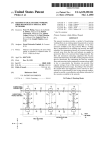
FIG. 1 illustrates a prior art scenario of resource allocation
and utiliZation in a blade center;
FIG. 2 illustrates a prior art method of resource allocation
in a blade center;
FIG. 3 illustrates a prior art method of resource allocation
in a blade center;
FIG. 4 illustrates resource availability and utiliZation in a
the blade servers present. In FIG. 2, each blade server is rated
at 300 W maximum poWer, and the poWer available in the
chassis is 1400 W. Therefore blade servers 1-4 may be poW
ered on under this allocation scheme consuming 1200 W of
blade center in an embodiment of the present invention;
20
poWer, but blade servers 5-6 can not be poWered on, even
25
FIG. 5 illustrates poWer utiliZation in a blade center in an
most of the time.
FIG. 3 illustrates an alternative prior art method for allo
cating poWer Within the same blade center chassis as referred
embodiment of the present invention;
FIG. 6 illustrates a timeline of poWer allocation for one
blade server in an embodiment of the present invention;
FIG. 7 illustrates a schematic diagram of a blade center
30
to in FIGS. 1 and 2. This approach, Where all of the systems
operate unconstrained, introduces the possibility of sponta
neously exceeding the poWer available to the systems. This
management subsystem;
FIG. 8 illustrates a front, top and right side exploded per
may cause the poWer supplies to fail and all dependent sys
spective vieW of a blade center chassis of the present inven
tion;
FIG. 9 illustrates a rear, top and left side perspective vieW
of the rear portion of the blade center chassis of the present
though 200 W of poWer remains available. In FIG. 1, the
ine?iciency of this method is further illustrated in vieW of the
percentage of available resources used by applications run
ning on blade servers 1-4, Which operate at loW utiliZation
35
tems to turn off immediately. A subset of the blade servers are
allocated poWer for them to run at a loWer percentage of their
maximum poWer consumption, for example as illustrated in
FIG. 3, either at 200 W or 250 W per blade server, for a total
invention;
of about 1350 W allocated poWer. Since the poWer allocation
FIG. 10 illustrates system components in one embodiment
is unenforceable, any blade server may consume a maximum
of the present invention;
FIG. 11 is a ?oW-chart of the poWer on portion of a poWer
40
of 300 W anytime during operation. Any spike in utiliZation
cycle process in one embodiment of the present invention;
and
by applications may result in an increase in aggregate poWer
FIG. 12 is a ?oW-chart of the poWer allocation portion of a
poWer cycle process in one embodiment of the present inven
tion.
monpoWer supply can provide, potentially causing all servers
consumption to over 1400 W, Which exceeds What the com
45
of having inoperable systems With periods Where the Work
DETAILED DESCRIPTION
In the folloWing description, numerous speci?c details are
set forth such as speci?c Word or byte lengths, etc. to provide
allocated to them cannot be performed.
FIG. 4 illustrates enforced resource availability and utili
50
a thorough understanding of the present invention. HoWever,
it Will be obvious to those skilled in the art that the present
invention may be practiced Without such speci?c details. In
other instances, Well-knoWn circuits have been shoWn in
block diagram form in order not to obscure the present inven
55
tion in unnecessary detail. For the most part, details concem
ing timing considerations and the like have been omitted
inasmuch as such details are not necessary to obtain a com
plete understanding of the present invention and are Within
the skills of persons of ordinary skill in the relevant art.
through the several vieWs.
servers can be allocated poWer suf?cient to meet their maxi
Zation in a blade center in an embodiment of the present
invention. For purposes of illustration, the same blade center
chassis con?guration as in the previous cases, FIGS. 1-3, is
referred to. HoWever, in this case, the chassis 100 (see FIG.
10) is equipped With an enforceable poWer allocation system
of the present invention, Which conforms to the architecture
embodied in FIGS. 11 and 12. In FIG. 4, each blade server 130
has a unique percentage of hardWare resources, CPU 138
cycles and DIMMs 139, enabled and poWered on for use by
the operating system 136 and applications 133. In the steady
60
Refer noW to the draWings Wherein depicted elements are
not necessarily shoWn to scale and Wherein like or similar
elements are designated by the same reference numeral
One prior art method for allocating poWer Within a blade
center chassis is illustrated in FIGS. 1 and 2. A subset of blade
in the chassis to catastrophically fail or to be shutdoWn. Thus
the prior art poWer allocation method of FIG. 3 introduces
both data reliability problems as Well as the general problem
65
state example illustrated in FIG. 4, the average utiliZation of
applications 133 running on a blade server 130 is kept bal
anced at 80% SST of the of resources made available to them
by a enforceable poWer allocation process of the present
invention, such as shoWn in one case by the process steps
1110 upon booting the operating system 136. Through arbi
tration and brokering, as in the process 1250, the percentage
of available resources may be increased to maintain an 80%
US 8,032,776 B2
7
8
SST. In the case of Work requests that result from a spike in
BIOS 137, Which may be embodied by ?rmWare stored on a
?ash memory device, may control the CPU 138 and DIMMs
139 via interface 132, Which may be SMI or another interface
application 133 resources, the hardWare resources (CPU 138,
memory 139) presented to the operating system are con
mechanism for controlling poWer consumption of CPU 138
and DIMMs 139 practiced Within the scope of the present
invention. A hardWare resource monitoring agent softWare
strained such that a utilization spike cannot cause the blade
server 130 to exceed the poWer allocated to it. If utiliZation
remains critically high, a given application may fail in a
fashion that is particular to it. For example, determinate Work
requests may not be servicable during periods Where utiliZa
134 communicates With the BIOS 137 and monitors the cur
rent state of CPU 138 cycles and DIMMs 139. The resource
tion remains critically high.
monitoring agent 134 communicates With the SP 135 via
interface 129, Which may be a kernel-mode driver in the
operating system 136 or other communications interface. The
FIG. 5 illustrates poWer utiliZation in a blade center in an
embodiment of the present invention. For purposes of illus
tration, the same blade center chassis con?guration (see FIG.
10) and enforceable poWer allocation scheme is referred to as
in FIG. 4. In FIG. 5, the absolute values for poWer utiliZation
puting load executed on the blade server 130. The operating
system 136 also executes the resource monitoring agent 134
are illustrated for each blade server 130. Note that the average
and is responsible for providing any necessary kernel-mode
poWer utiliZation is kept just beloW the maximum poWer
driver routines or hardWare interface management services.
FIG. 11 is a ?oW-chart of the poWer on portion 1110 ofa
poWer cycle process in one embodiment of the present inven
tion. A MM 110 present in a blade center chassis 100 Will be
operating system 136 and applications 133 comprise the com
utiliZation at the enabled capacity on each blade server 130.
This illustrates the steady state performance of the method to
regulate the enabled capacity of the present invention. In FIG.
5, the aggregate poWer allocated is about 1200 W, comparable
20
responsible for allocating and brokering poWer resources
to the situation in FIGS. 1-3. HoWever, the present invention
from a common poWer supply 140 among the blade servers
effectively mitigates the aforementioned risks of the prior art
130 installed in the slots 120 in the chassis 100. There are
multiple blade servers 130, each of Which contain an SP 135
allocations methods in FIGS. 1-3.
FIG. 6 illustrates a timeline of poWer allocation for one
blade server 130 in an embodiment of the present invention.
For purposes of illustration, the same blade center chassis
25
con?guration and enforceable poWer allocation scheme is
referred to as in FIGS. 4 and 5. HoWever, FIG. 6 shoWs hoW
transitions in poWer allocation over time are managed by the
present invention. Before the time t5, the utiliZation remains
30
utilization begins to rise and exceeds TUT for 200 W, such
common pool. After time tn, the poWer allocated is again 200
W and the utiliZation remains beloW TUT for 200 W. This
example is illustrative for one blade server 130 undergoing
stepping level. Assuming that N blade servers 130 are present
in the blade center chassis 100, the MM 110 then allocates
35
chassis 100 (maintained by the MM 110), historical for the
40
1210. In other embodiments of the present invention, the
45
blade server 130 (maintained by the blade server 130), deter
mined by an external authority, or otherWise rule based in
various other embodiments of the present invention. The dif
ference betWeen the MAP and the aggregate poWer allocated
to each blade server 130 is the amount of poWer initially
available in the common pool. The allocation of poWer 1113
by the MM 110 is executed by communicating a message
The system components and architecture for controlling
poWer in a blade center chassis are illustrated in FIG. 10. A
blade center chassis 100 contains the folloWing components
relevant for controlling poWer: blade servers 130 Which reside
in the chassis slots 120; management modules (MM) 110
1113 a ?xed amount of poWer, in one example a value equiva
lent to MAP/N, to each blade server 130. Alternate methods
for determining hoW much poWer to provide 1113 each indi
vidual blade server 130 may be policy based, historical for the
tWo transitions to increase poWer 1250 then reduce poWer
order and number of transitions may vary on each blade
server 130 in each individual chassis 100.
BIOS 137 via SMI or other interface 131 to determine 1112
poWer consumption of each DIMM, capacity of each DIMM,
CPU stepping levels, and CPU poWer consumption at each
beloW TUT for a poWer allocation of 200 W. At time t5, the
that arbitration for additional poWer occurs by a process 1250,
resulting in an additional 50 W of poWer allocated to the blade
server 130 from the common pool. Thus from time t5 to time
tn, the poWer allocated to the blade server 130 is 250 W. At
time tn, the utiliZation falls beloW TDT for a poWer allocation
of 250 W, such that the blade server 130 frees up 50 W of
poWer by a process 1210 Which are brokered back into the
and a BIOS 137, running an operating system 136. At system
initialiZation 1101, the MM 110 determines the amount of
poWer available in the chassis 100 by reading 1111 the vital
product data (VPD) of the poWer supplies 140 in the chassis
100, resulting in a maximum available poWer (MAP). For
each blade server 130, the SP 135 communicates With the
50
from the MM processor 117 via interface 125 to the SP 135.
Based on the poWer consumption values determined in 1112
of memory DIMMs and the CPU at different stepping levels,
the SP 135 informs the BIOS 137 via SMI or other interface
131 of the initial con?guration that should be made available
Which may contain their oWn MM processor 117; a common
to the operating system 136. This con?guration comprises the
poWer supply 140 and ventilators 150; and communication
interfaces betWeen these components 125, 141, 151. In a
blade center used to practice the present invention, the service
number of DIMMs 139 to enable (and Which speci?c mod
ules thereof), and the throttling step level that the CPU 138
55
supply 140 via bus 141 and the ventilator 150 via a fan bus
151. The bidirectional interface 125 betWeen the MM proces
sor 117 and the SP 135, may be a multi-drop RS-485 inter
alloWs the operating system 136 to boot 1115. After the blade
server 130 is booted, the poWer allocation portion 1250, 1210
of the poWer cycle begins 1201, and repeats until the blade
60
server 130 is shut doWn 1202.
FIG. 12 is a ?oW-chart of the poWer allocation portion
1250, 1210 of a poWer cycle process in one embodiment of
the present invention. The poWer allocation events include
transferring poWer from the common pool to a blade server
face. Other interface protocols for 125 may be implemented.
The control buses 141, 151 may be I2C interfaces. On the
blade server 130, the SP 135 communicates With a BIOS 137
(basic input/output system) via System Management Inter
should be set to. The BIOS 137 then sets the appropriate
con?guration 1114 via interface 132, and subsequently
processor (SP) 135 on a blade server 130 communicates, via
the bidirectional interface 125, With the MM processor 117 on
the MM 110. The MM 110 interfaces With the common poWer
65
130 requiring a higher poWer allocation 1250 and transferring
face SMI 131 for controlling the cycle frequency of the CPU
poWer from a blade server 130 utiliZing a loWer amount of
138 or poWer to the individual banks of DIMMs 139. The
poWer than currently allocated back to the common pool
US 8,032,776 B2
10
1210. The power cycle process ends 1202 after the blade
server 130 is powered down 1216.
yield recorded historical threshold values for proactively trig
When power allocation to blade server 130 is increased
1250, an initial determination 1251 by the resource monitor
gering the determination 1211. In yet another case, the deter
mination 1211 may be schedule driven, where an adminstra
ing agent software 134, which monitors CPU 138 and
across several power cycle processes 1110, 1250, 1210 may
5
tor has recogniZed that troughs in application utiliZation will
occur at a particular time and date, or where a regular pattern
memory 139 utilization values SST and TUT, has been made
of utiliZation, such as normal business hours, require sched
that more resources are required. This determination 1251
ule-dependent resource management. When the resource
may be result of a trend analysis, as illustrated in FIG. 6,
policy driven by an external entity, such as an administrator,
rule-based, or derived from any combination of systematic
monitoring software agent 134 has determined 1211 that
fewer resources are required, the agent 134 issues a service
request to the SP 135 to disable some of the enabled hardware
resources, CPU 138 cycles and/or DIMMs 139. The SP 135
then calculates 1212 the additional power that can be made
criteria applied in individual embodiments of the present
invention. In one case, the determination 1251 may result
from considerations which balance the responsiveness of the
system versus minimizing overall power consumption, such
availabe to the common pool by disabling the requested hard
ware resources. The SP 135 then issues a request 1213 to the
as the implementation of a control algorithm. In another case,
a trend analysis across several power cycle processes 1110,
1250, 121 0 may yield recorded historical threshold values for
utiliZation will occur at a particular time and date, or where a
BIOS 137 via SMI 131 by requesting that the CPU 138 speed
be stepped down, or additional memory DIMMs 139 be dis
abled as is appropriate. After the power consumption of the
blade server 130 has been reduced 1213 by the BIOS, the SP
135 noti?es 1214 the MM 110 that additional power has been
made available to the common pool. The MM 110, acting in
its capacity as the resource broker under consideration of all
regular pattern of utiliZation, such as normal business hours,
require schedule-dependent resource management. When the
blade server 130 and sends a con?rmation response 1216
proactively triggering the determination 1251. In yet another
case, the determination 1251 may be schedule driven, where
an adminstrator has recogniZed that spikes in application
20
applicable rules and policies, de-allocates the power for the
resource monitoring software agent 134 has determined 1251
that more resources are required, the agent 134 issues a ser
vice request to the SP 135 to enable the additional hardware
resources, CPU 138 cycles and/or DIMMs 139. The SP 135
then calculates 1252 the additional power required to enable
the requested hardware resources. The SP 135 then issues a
request 1253 to the MM 110 which is responsible for broker
ing the power in the common pool for the additional amount
25
30
back to the SP 135 indicating the actual amount of additional
power that has been allocated to the common pool from the
blade server 130. Note that the blade server 130 is required to
relinquish power in a timely manner back to the common pool
1210 for the MM 110 to be able to broker future requests for
more power 1250 from other blade servers 130 in the chassis
100.
FIG. 7 is a schematic diagram of a blade center chassis
of power. If the MM 110, acting in its capacity as the resource
broker under consideration of all applicable rules and poli
management subsystem, showing engineering details of the
cies, determines 1254 that more power should be made avail
able to the requesting blade server 130, the MM 110 will send
a con?rmation response 1255 back to the SP 135 indicating
the actual amount of additional power that is allocated to the
blade server 130 from the commonpool. Note that the amount
of power con?rmed by the MM 110 may differ from, i.e. may
represented schematically by MM 110, and showing engi
individual management modules MM1-MM4, previously
35
neering details of the individual components contained in
previous schematic representations of blade center chassis
100. Referring to this ?gure, each management module has a
separate Ethernet link to each one of the switch modules SMI
135 will then con?rm the directives of the MM 110 to the
through SM4. Thus, management module MM1 is linked to
switch modules SMI through SM4 via Ethernet links MM1
ENet1 through MM1-ENet4, and management module MM2
BIOS 137 via SMI 131 by requesting that the CPU 138 speed
is linked to the switch modules via Ethernet links MM2
be lower than, the amount requested by the SP 135. The SP
be stepped up, or additional memory DIMMs 139 be enabled
as is appropriate. Note that the CPU step increase and number
of additional DIMMs enabled may differ from the original
request to the SP 135 by the BIOS 137. The BIOS 137 then
sets the hardware resources 1256 in compliance with the
request by the SP 135. Note that the MM 110 remains the
governing authority for all increases in power allocated in the
chassis 100 during brokering 1250 and must approve all
40
ENet1 through MM2-ENet4. In addition, the management
modules are also coupled to the switch modules via two well
45
management modules are also coupled to the power modules
(previously represented schematically by 140) PM1 through
50
requests for additional power from the blade servers 130. The
blade servers 130 must conform to the directives of the MM
110 and must be enabled to conform to the architecture
requirements.
When power allocation to blade server 130 is decreased
PM4 via two serial I2C buses (corresponding to interface 141)
PM-I2C-BusA and PM-I2C-BusB. Two more I2C buses
Panel-I2C-BusA and Panel-I2C-BusB are coupled to media
tray MT and the rear panel. Blowers BL1 and BL2 (previ
ously represented schematically by 150) are controlled over
55
1210, a initial determination 1211 by the resource monitoring
agent software 134, which monitors CPU 138 and memory
139 utiliZation values SST and TDT, has been made that
separate serial buses Fan1 and Fan2 (corresponding to inter
face 151). Two well known RS485 serial buses RS485-A and
RS485-B are coupled to server blades PB1 through PB14 for
“out-of-ban ” communication between the management
modules and the server blades.
resources may be freed. This determination 1211 may be
FIG. 8 illustrates a front, top and right side exploded per
spective view of a blade server system, showing engineering
details of the individual components contained in previous
schematic representations of blade center chassis 100. Refer
ring to this ?gure, main chassis CH1 houses all the compo
result of a trend analysis, as illustrated in FIG. 6, policy driven
by an external entity, such as an administrator, rule-based, or
derived from any combination of systematic criteria applied
in individual embodiments of the present invention. In one
case, the determination 1211 may result from considerations
which balance the responsiveness of the system versus mini
known serial I2C buses SM-I2C-BusA and SM-I2C-BusB,
which provide for “out-of-band” communication between the
management modules and the switch modules. Similarly, the
65
nents of the blade server system. Up to 14 processor blades
miZing overall power consumption, such as the implementa
PB1 through PB14 (or other blades, such as storage blades)
tion of a control algorithm. In another case, a trend analysis
are hot pluggable into the 14 slots in the front of chassis CH1.
US 8,032,776 B2
11
12
The term “server blade”, “blade server , processor blade”,
for cooling, poWer, control and sWitching. Chassis CH2 slides
or simply “blade” is used throughout the speci?cation and
and latches into the rear of main chassis CH1.
TWo hot pluggable bloWers BL1 and BL2 (previously rep
claims, but it should be understood that these terms are not
resented schematically by 150) include backWard-curved
limited to blades that only perform “processor” or “server”
functions, but also include blades that perform other func
tions, such as storage blades, Which typically include hard
disk drives and Whose primary function is data storage.
Processor blades provide the processor, memory, hard disk
impeller bloWers and provide redundant cooling to the blade
server system components. Air?oW is from the front to the
rear of chassis CH1. Each of the processor blades PB1
through PB14 includes a front grille to admit air, and loW
storage and ?rmware of an industry standard server. In addi
pro?le vapor chamber based heat sinks are used to cool the
tion, they include keyboard, video and mouse (KVM) selec
processors Within the blades. Total air?oW through the system
chassis is about 300 CFM at 0.7 inches H2O static pressure
drop. In the event of bloWer failure or removal, the speed of
the remaining bloWer automatically increases to maintain the
required air ?oW until the replacement unit is installed.
BloWer speed control is also controlled via a thermistor that
constantly monitors inlet air temperature. The temperature of
tion via a control panel, an onboard service processor, and
access to the ?oppy and CD-ROM drives in the media tray. A
daughter card may be connected via an onboard PCl -X inter
face and is used to provide additional high-speed links to
various modules. Each processor blade also has a front panel
With 5 LED’s to indicate current status, plus four push-button
sWitches for poWer on/ off, selection of processor blade, reset,
the blade server system components are also monitored and
and NMI for core dumps for local control.
Blades may be “hot sWapped”, meaning removed or
installed in the poWer on state, Without affecting the operation
of other blades in the system. A blade server is typically
bloWer speed Will increase automatically in response to rising
temperature levels as reported by the various temperature
20
sensors.
Four hot pluggable poWer modules PM1 through PM4
implemented as a single slot card (394 mm><227 mm); hoW
(previously represented schematically by 140) provide DC
ever, in some cases a single processor blade may require tWo
operating voltages for the processor blades and other compo
or more slots. A processor blade can use any microprocessor 25 nents. One pair of poWer modules provides poWer to all the
technology as long as it is compliant With the mechanical and
management modules and sWitch modules, plus any blades
electrical interfaces, and the poWer and cooling requirements
that are plugged into slots 1-6. The other pair of poWer mod
ules provides poWer to any blades in slots 7-14. Within each
pair of poWer modules, one poWer module acts as a backup for
the other in the event the ?rst poWer module fails or is
of the blade server system.
For redundancy, processor blades have tWo signal and
poWer connectors; one connected to the upper connector of
30
the corresponding slot of midplane MP (described beloW),
removed. Thus, a minimum of tWo active poWer modules are
and the other connected to the corresponding loWer connector
of the midplane. Processor Blades interface With other com
required to poWer a fully featured and con?gured chassis
loaded With 14 processor blades, 4 sWitch modules, 2 bloW
ers, and 2 management modules. HoWever, four poWer mod
ules are needed to provide full redundancy and backup capa
bility. The poWer modules are designed for operation betWeen
anAC input voltage range of 200 VAC to 240VAC at 50/60 HZ
ponents in the blade server system via the folloWing midplane
interfaces: 1 . Gigabit Ethernet (2 perblade; required); 2. Fiber
Channel (2 per blade; optional); 3. management module serial
35
link; 4.VGA analog video link; 4. keyboard/mouse USB link;
5. CD-ROM and ?oppy disk drive (EDD) USB link; 6. 12
VDC poWer; and 7. miscellaneous control signals. These
interfaces provide the ability to communicate With other com
ponents in the blade server system such as management mod
ules, sWitch modules, the CD-ROM and the EDD. These
interfaces are duplicated on the midplane to provide redun
dancy. A processor blade typically supports booting from the
and use an IEC320 C14 male appliance coupler. The poWer
40
45
media tray CDROM or EDD, the netWork (Fiber channel or
Ethernet), or its local hard disk drive.
A media tray MT includes a ?oppy disk drive and a CD
ROM drive that can be coupled to any one of the 14 blades.
The media tray also houses an interface board on Which is
mounted interface LED’ s, a thermistor for measuring inlet air
temperature, and a 4-port USB controller hub. System level
interface controls consist of poWer, location, over tempera
ture, information, and general fault LED’s and a USB port.
50
Midplane circuit board MP is positioned approximately in
55
nents that provide basic management functions such as con
Management modules also provide other functions required
to manage shared resources, such as the ability to sWitch the
common keyboard, video, and mouse signals among proces
sor blades.
Although the present invention and its advantages have
been described in detail, it should be understood that various
changes, substitutions and alterations can be made herein
Without departing from the spirit and scope of the invention as
de?ned by the appended claims.
tors; the top roW including connectors MPC-S1-R1 through
MPC-S14-R1, and the bottom roW including connectors
MPC-S1-R2 through MPC-S14-R2. Thus, each one ofthe 14
60
R2) and each pair of midplane connectors mates to a pair of
connectors at the rear edge of each processor blade (not
visible in FIG. 8).
FIG. 9 is a rear, top and left side perspective vieW of the rear
portion of the blade server system. Referring to FIGS. 8 and
9, a chassis CH2 houses various hot pluggable components
Management modules MM1 through MM4 (previously
represented schematically by 110) are hot-pluggable compo
trolling, monitoring, alerting, restarting and diagnostics.
the middle of chassis CH1 and includes tWo roWs of connec
slots includes one pair of midplane connectors located one
above the other (e.g., connectors MPC-S1-R1 and MPC-S1
modules provide +12 VDC output to the midplane from
Which all blade server system components get their poWer.
TWo +12 VDC midplane poWer buses are used for redundancy
and active current sharing of the output load betWeen redun
dant poWer modules is performed.
What is claimed is:
1. A blade center chassis apparatus comprising:
a plurality of blade servers populating a plurality of chassis
slots;
65
a management module;
a poWer supply common to said plurality of chassis slots
for poWering said plurality of blade servers, Wherein
said poWer supply further comprises a plurality of poWer
modules; and
US 8,032,776 B2
14
13
circuitry built into said management module operable for:
4. The apparatus of claim 1, Wherein said circuitry built
reading a total power capacity of said blade center chas
into said management module, operable for said brokering
sis by querying each of said plurality of poWer mod
said total poWer capacity in said blade center chassis by
changing said individual amount of poWer allocated to each
ules installed in said blade center chassis;
of said plurality of blade servers, further comprises circuitry
calculating a maximum poWer load dissipated by said
operable for:
plurality of blade servers by querying a poWer con
sumption value of each of said plurality of blade serv
receiving a notice from a service processor on a blade
server that the poWer consumption of said blade server
ers;
has been decreased, Wherein said notice includes the
allocating an individual amount of poWer to each of said
plurality of blade servers, Wherein a total amount of
individual poWer allocated remains less than said total
poWer capacity of said blade center chassis; and
brokering said total poWer capacity in said blade center
chassis by changing said individual amount of poWer
amount that said poWer consumption of said blade server
has been decreased; and
transferring an individual decrease in allocation of poWer
from said blade server to the available amount of poWer
allocated to a common pool, in relation to said amount
15
allocated to each of said plurality of blade servers.
2. The apparatus of claim 1, Wherein said circuitry built
into said management module operable for said querying a
poWer consumption value of each of said plurality of blade
servers further comprises circuitry operable for:
Wherein said service processor further comprises circuitry
operable for:
determining poWer consumption settings of poWer-con
issuing a service request to a service processor on said
blade server; and
suming resources on said blade server by communicat
ing With a BIOS on said blade server;
receiving poWer consumption values from said service pro
calculating poWer consumption values based on said poWer
cessor.
3. The apparatus of claim 1, Wherein said circuitry built
25
into said management module, operable for said brokering
said blade server;
Wherein said service processor further comprises circuitry
30
receiving a request from a service processor on a blade
determining poWer consumption settings of poWer-con
server;
35
from poWer allocated to a common pool to said blade
server;
con?rming said individual increase in allocation of poWer
to said blade server.
suming resources on said blade server;
issuing a request to a BIOS of said blade server to apply
said poWer consumption settings; and
deactivating by said BIOS of said poWer-consuming
resources, Wherein said deactivating results in a
determining an individual increase in allocation of poWer
to said blade server from the available amount of said
poWer allocated to said common pool; and
operable for:
enforcing a reduced amount of allocated poWer to said
blade server, further comprising the steps of:
server for an increase in the poWer allocated to said blade
determining When said increase in the poWer allocated to
said blade server may be granted by transferring poWer
consumption settings; and
communicating said poWer consumption values to a man
agement module in a blade center chassis populated by
said total poWer capacity in said blade center chassis by
changing said individual amount of poWer allocated to each
of said plurality of blade servers, further comprises circuitry
operable for:
that said poWer consumption of said blade server has
been decreased.
5. A blade server device comprising a service processor for
communications and resource management functions,
40
decrease in poWer consumption; and
notifying said management module of said reduced
amount of allocated poWer to said blade server.
*
*
*
*
*