1
US006529298B1
(12) United States Patent
(10) Patent N0.:
Phelps et al.
(54)
(75)
US 6,529,298 B1
(45) Date of Patent:
Mar. 4, 2003
METHOD OF DEACTIVATING WORKING
5,903,370 A
*
5/1999 Johnson .................... .. 359/119
FIBER RESOURCES IN OPTICAL RING
6,046,832 A
*
4/2000
Fishman . . . . . .
NETWORKS
6,052,210
A
*
4/2000
Nathan
6,222,653
B1
*
4/2001
Asahi
Inventors: Peter W_ Phelps, Nepean (CA); Evert
6,295,146 B1 *
........
... ... ... ... .
. . . ..
359/119
. . . ..
359/110
9/2001 Nathan et a1. ............ .. 359/119
E. Deboer, Nepean (CA); Robert
>I Cited by examiner
Caporuscio, Montreal (CA); Johnny
Leung, Kirkland (CA); Pau] Charren,
Primary Examiner—Kinfe-Michael Negash
St. Lambert (CA); Louis R. Pare, St.
. . . .. 359/119
Bruno (CA); Joseph Olajubu, Essex
(57)
(GB)
The present invention provides a method of deactivating
_
_
_
ABSTRACT
working ?bers in an existing optical ring network or system
(73) AsslgneeZ £2159] Networks Llmlted> St- Laurent
for a cost-effective and ef?cient allocation of the ?ber
resources available in the ring network. When a working
*
_
_
( ) Nonce:
_
_
_
?ber is underutilized in an existing ring network, the traf?c
Sub]eCt_tO any dlsclalmeri the term of thls
scheduled for transmission thereon is re-routed around the
Patent 15 extended or adlusted under 35
network away from the ?ber and lockouts are applied to
USC‘ 154(k)) by 0 days‘
prevent the ?ber to be removed from being protected. The
?ber and associated connecting equipment thus become
unused and unnecessary for traf?c carrying purposes and can
then be deactivated. By eliminating the need for working
(21) Appl- NO-I 09/471,138
(22) Filed
Dec 23 1999
'
(51)
'
’
?bers and associated optics equipment on spans where traf?c
Int. Cl.7 .............................................. .. H04B 10/08
is low or non-existent, the invention can provide ?ber
(52)
359/110; 359/119
capacity savings of up to ?fty percent on each span while
(58)
Field of Search ............................... .. 359/ 110, 119,
359/173
retaining full protection usage- According to the inventiom
the unused ?bers and equipment can be removed or alter
(56)
natively be re-provisioned for use in other network con?gu
rations to provide a cost-effective and ef?cient allocation of
References Cited
the resources available in the network.
US. PATENT DOCUMENTS
5,717,796 A *
2/1998 Clendening ............... .. 359/119
36 Claims, 4 Drawing Sheets
_ _ 41111111111‘ ----------- "I____________________,_:_ _________ _ _ 11111111111: - ' |
BI-DIRECTIUNAL:
WDRKINGFIBER.
‘2
I
I 30
I
g
5“
14
a
I
i 32
1
I
52
15
a
:
i
I
.5“; .NOBE
P .70
; I I 72 II a
Bl-[IIRECTIUNAL
PRDTECTIUNFIBER; f:I :x
II
I
iszfg @845
l 1 LE‘*\J6l:
I
.
.
.
.
16%? =
i
1 NUDE
.
.
.
.
.
-
.
.
.
.
.
.
5
:is
.
|
:
<
i
NBBE...I'....
‘II 78 : : 80 ;
lI ‘f:I I:x i
1
E
5 5 E
I Q63?
:
5
l
.
I
|
.
NUDE M4?
......
II74 : : 7sII a
1l f:I :\'
l
I
I
.
.
-
.
.
-
.
-
.
S
Q
42
54
.
.
.
.
.
.
.
.
.
I521‘? a
I
- I
NUDE
.
.
.
-
.
I
:?’
.
.
.
.
s
I‘
56
I
'
I
64 (CD
.
I
=
NUDE
I
l
;
s
:
l
.
-
|
-
-
.
'
l
Q
I
:
I
|
.
:w'\/92i
E ?}\/65|:
I
44
.
.
.
.
.
'
.
.
.
.
.
..J....
|
__ I_
15
l
l
20
i
i
22
I
\_BLSH
_I_______________________ i__wi___:_____—______:____:l__________ _T___________:____J_2_.
NETWORK
SECOND BLSR RING
N
FIRST B1L1SR mm;
13
10
U.S. Patent
Mar. 4, 2003
Sheet 1 0f 4
'2
-.m3DOJZ-.h_+:mD3Z".:M“-Tm
||J||_| +|1I | r|
h
u
n
h
32,555;
2_
ESu
x
_
u
.x
Ea_emm8
émmzlml?
égn
M
“
M
u
n
X
X
T»?
Maw/m
m
\NmmmNm/m
.\,8(\g
:i
...
.
.
...
H
.
u
_
.
u
_
_
_
_
_
n
_
_
u
_
_
_
u
_
m
22m
So:
E26MP
Q?"3SE2bx5a;
7.5E._m5:
_
_
_
_
.
I
_
.
.I
-_
_
_
_
_
u
_
n
u
_
...
“
n
u
n
u
H
_
n
H
ma
u
n
3
lf j u
w
cU
h
u
__
ll
5%502|._|
W82J
US 6,529,298 B1
_ .,
28lmX.w9-iaV%sl
5%02E$52z :
>>wGE
M
w
US 6,529,298 B1
1
2
METHOD OF DEACTIVATING WORKING
FIBER RESOURCES IN OPTICAL RING
NETWORKS
netWorks or continental netWorks Where traffic is largely
concentrated on East-West spans and little if any traf?c is
transmitted along North-South spans. In these netWorks, the
?ber capacity on North-South spans is not ef?ciently utiliZed
and in many instances may not be needed for traf?c carrying
purposes.
FIELD OF THE INVENTION
In addition to this ineffective use of ?bers, the accommo
This invention relates generally to optical ring networks
and more particularly to a method of deactivating Working
?ber resources in optical ring netWorks.
dation of multiple ?bers betWeen nodes necessitates at each
node the installation of connection equipment for each ?ber.
10
BACKGROUND ART
Today’s optical transport netWorks employ a number of
different topologies to satisfy increasing demands for net
Work simplicity, cost containment, bandWidth ef?ciency and
particularly on spans Where the ?ber capacity is underuti
liZed.
Therefore, it Would be desirable to use the existing
15
survivability. Common netWork topologies include point-to
point terminal con?gurations, linear add/drop multiplexer
con?gurations and ring con?gurations. Of all these different
topologies, ring con?gurations are often the preferred net
Working ?ber capacity more ef?ciently in optical ring net
Works or alternatively deactivate underutiliZed ?bers and
associated equipment so that they can be removed or
re-provisioned for use in other netWork con?gurations.
SUMMARY OF THE INVENTION
The present invention provides a method of deactivating
Working ?ber resources in an existing optical ring netWork
Work con?guration for applications requiring high transport
capacity.
or system for a cost-effective and ef?cient allocation of the
In optical ring networks, the bandWidth available in each
?ber interconnecting nodes can be allocated in various Ways
to meet different capacity demands. In some ring
con?gurations, the bandWidth available for transport can be
HoWever, duplicating this equipment for each ?ber may also
prove to have a considerable impact on the system cost,
25
provisioned as a single optical transmission path. HoWever,
in the vast majority of ring con?gurations, the bandWidth is
?ber resources available in the ring netWork. The invention
can be applied to deactivate physical Working ?bers as Well
as Working channels or Wavelengths provisioned on a physi
cal Working ?ber. The term ?ber is therefore used to denote
both a physical ?ber and a channel or Wavelength provi
sioned on a physical ?ber.
partitioned into channels or Wavelengths to increase capac
it is common to use the term ?ber generally to denote traf?c
According to the invention, When a Working ?ber betWeen
any tWo nodes in an existing ring netWork is underutiliZed,
the traf?c scheduled for transmission thereon is re-routed
around the netWork aWay from the ?ber. As a result, the ?ber
carrying capacity. As such, in addition to denote physical
and associated connecting equipment thus become unused
?bers, the term ?ber can also be used to denote single
channels or Wavelengths in a physical ?ber. For clarity and
unless stated otherWise, the term ?ber as applied generally
and unnecessary for traffic carrying purposes and can then be
deactivated.
ity.
In optical ring netWorks as in other optical con?gurations,
35
Advantageously, the present invention eliminates the need
for Working ?bers and associated optics equipment on spans
to optical netWorks is hereinafter used to denote both a
physical ?ber and a single channel or Wavelength Within a
Where traf?c is loW or non-existent and can provide ?ber and
physical ?ber.
In addition to providing large capacity, optical ring sys
equipment capacity savings of up to ?fty percent on each
span While retaining full protection usage. According to the
invention, the unused ?bers and equipment can be removed
or alternatively be re-provisioned to provide a cost-effective
tems are also designed With redundant equipment to have
other attributes such as, for example, bidirectionality and/or
increased reliability to reduce service failures. In conven
tional unidirectional and bidirectional ring systems for
example, multiple ?bers are commonly installed to achieve
45
transmit and receive operations. Additional ?bers are also
installed to “protect” the Working ?bers in the event of a link
revieW of the folloWing description of speci?c embodiments
of the invention in conjunction With the accompanying
(span) failure. Current ring protection schemes include dedi
?gures.
cated protection, 1 protection ?ber for each ?ber or 1:1
protection Which can be used in both path sWitched and line
BRIEF DESCRIPTION OF THE DRAWINGS
sWitched con?gurations.
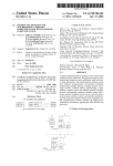
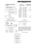
FIG. 1 is a diagram of a conventional four-?ber bidirec
In optical ring netWorks, some spans that interconnect
nodes are not required to carry Working traf?c. This is either
because there is no requirement for traf?c or because there
is too much capacity available and it cannot all be ef?ciently
and ef?cient allocation of the resources available in the
netWork.
Other aspects and features of the present invention Will
become apparent to those ordinarily skilled in the art upon
tional line sWitched ring (BLSR) netWork featuring a plu
rality of Working ?bers;
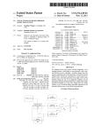
FIG. 2 is a diagram of the four-?ber BLSR netWork of
55
used. This is particularly true for dense Wavelength division
FIG. 1 With a reduced plurality of Working ?bers according
to a preferred embodiment of the invention;
multiplex (DWDM) systems Where the number of channels
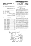
FIG. 3 is a diagram of a conventional four-?ber matched
or Wavelengths available on some spans can very Well
node BLSR netWork featuring a plurality of Working ?bers;
exceed the transport capacity required.
Currently, all spans separating adjacent nodes in a ring
con?guration have to be ?ber equipped because of the
and
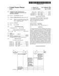
FIG. 4 is a diagram of the four-?ber matched node BLSR
netWork of FIG. 3 With a reduced plurality of Working ?bers
protection usage that is necessary on a ring con?guration.
according to another preferred embodiment of the invention.
HoWever, this requirement only makes use of protection
?bers. On spans Where traffic is loW or non-existent, the
Working ?bers present may never be used. As a result, the
?ber capacity available in some optical ring netWorks may
be underutiliZed. This is particularly true for long distance
65
DETAILED DESCRIPTION OF THE
PREFERRED EMBODIMENTS
The present invention provides a method of deactivating
Working ?ber resources in an existing optical ring netWork
US 6,529,298 B1
3
4
or system for a cost-effective and ef?cient allocation of the
cal ?bers or Wavelengths on each span 50, 52, 54, 56, 60, 61,
?ber resources available in the ring network. The invention
applies to the deactivation of physical Working ?bers as Well
as Working channels or Wavelengths. For clarity and
generality, the term “?ber” as used in the description of the
62, 63, 64, 65 to meet higher channel capacity requirements.
Conversely, a tWo-?ber BLSR con?guration could be used
Where each span 50, 52, 54, 56, 60, 61, 62, 63, 64, 65 is
implemented using a single bidirectional ?ber for both
Working and protection bandWidth. In the folloWing descrip
preferred embodiments provided beloW denotes a physical
?ber or a channel/Wavelength provisioned on a physical
tion and for the purpose of eXample only, the BLSR netWork
?ber.
The invention can be used in any optical netWork or
system for optimizing the use of ?ber equipment and con
In the BLSR netWork 10, traf?c is typically routed With
standard netWork management applications such as the
10 is assumed to be a four-?ber netWork.
Well-knoWn integrated netWork management (INM). For the
nections available on spans Where traf?c is loW or non
eXistent. According to the invention, the traffic present on
underutiliZed ?bers is re-routed making these ?bers unused
and unnecessary for traf?c carrying purposes. The unused
Working ?bers and associated equipment are then
purpose of eXample, it is hereinafter assumed that the
netWork management application used in the BLSR netWork
10 to route traf?c is INM.
15
de-activated and can be removed or alternatively
re-provisioned for use in other netWork con?gurations.
nodes 12, 14, 16, 18, 20, 22 along the East-West Working
?ber 30, 32, 42, 44 and the North-South Working ?bers 82,
84, 86, 88, 90, 92 present in the netWork 10. As is
In a preferred embodiment, the invention is used in a
bidirectional line sWitched ring (BLSR) netWork. An
eXample of a conventional four-?ber BLSR optical netWork
conventional, a localiZed controller present at each node 12,
With Which the invention can be used is shoWn in FIG. 1
generally denoted by 10. The BLSR netWork 10 consists of
multiple rings interconnected at common nodes 12, 14, 16,
18, 20, 22 connected to form a series of interWorking rings.
For the purpose of example, FIG. 1 only shoWs tWo com
14, 16, 18, 20, 22 supports the protection capabilities of span
and ring sWitches redirecting traf?c around failures. In the
event of a failure or degradation of a Working ?ber, the
25
outage. In this mode, the interrupted traf?c is redirected from
the defective Working ?ber onto a protection ?ber available
betWeen the affected nodes 12, 14, 16, 18, 20, 22 thereby
maintaining service for all terminating (span) and pass
a number of bidirectional East-West and North-South ?ber
spans Which can provide Working and protection transport
betWeen the nodes 12, 14, 16, 18, 20, 22.
through (ring) traf?c. If a fault affects an entire ?ber span
betWeen any tWo adjacent nodes 12, 14, 16, 18, 20, 22 (eg
a node failure or a cable cut of both Working and protection
?bers in the ?ber span), the affected traf?c can be re-directed
35
protection ?ber 34, 36 (shoWn as a dotted line). Similarly,
the nodes 18, 20, 22 are interconnected With bidirectional
East-West ?ber spans 54, 56 each formed of a bidirectional
20, 22 have to be ?ber equipped because of the protection
this requirement only makes use of the protection ?bers 34,
36, 38, 40, 70, 72, 74, 76, 78, 80. If there are ?ber spans 50,
52, 54, 56, 60, 61, 62, 63, 64, 65 in the netWork 10 Where
traffic is light, the Working ?bers in these spans 50, 52, 54,
56, 60, 61, 62, 63, 64, 65 may be under-utiliZed and in some
?ber 38, 40 (dotted line).
45
BetWeen these nodes 12, 18, the span 61 provides North
South connectivity for traf?c circulating in ring 11 While the
span 60 provides connectivity for traf?c circulating in an
cases unused. In optical ring netWorks such as the BLSR
netWork 10, it is quite common that traf?c is concentrated on
East-West ?ber spans With little or no traf?c transmitted
along North-South spans. In such netWorks, the Working
adjacent ring (not shoWn). Similarly, node 14 is intercon
?ber bandWidth available on these North-South spans is not
ef?ciently utiliZed and in many instances may not even be
nected With node 20 via a second pair of North-South ?ber
spans 62, 63 and node 16 is interconnected With node 22
With a third pair of North-South ?ber spans 64, 65 Where
each span provides North-South connectivity for a particular
ring. Each North-South ?ber span 60, 61, 62, 63, 64 and 65
consists of a Working ?ber 82, 84, 86, 88, 90, 92 (full line)
around the netWork 10 by ring protection sWitching.
In the BLSR netWork 10, all ?ber spans 50, 52, 54, 56, 60,
61, 62, 63, 64, 65 separating adjacent nodes 12, 14, 16, 18,
usage that is necessary on a ring protection sWitch. HoWever,
Working ?ber 42, 44 (full line) and a bidirectional protection
The nodes 12, 14, 16 are respectively interconnected With
the nodes 18, 20, 22 With a number of North-South ?ber
spans. More speci?cally, node 12 is interconnected With
node 18 With a ?rst pair of North-South ?ber spans 60, 61.
nodes 12, 14, 16, 18, 20, 22 can enter a span sWitching mode
to redirect traffic aWay from the fault and prevent a service
plete rings Where a ?rst ring 11 is formed of nodes 12, 14,
18, 20 and a second ring 13 is formed of nodes 14, 16, 20,
22. The nodes 12, 14, 16, 18, 20, 22 are interconnected With
More speci?cally, the nodes 12, 14, 16 are interconnected
With bidirectional East-West ?ber spans 50, 52 Where each
East-West ?ber span 50, 52 consists of a bidirectional
Working ?ber 30, 32 (shoWn as a full line) and a bidirectional
INM provides the necessary functionality to route traf?c
around the BLSR netWork 10. In the absence of failures,
INM manages the routing of Working traf?c betWeen the
needed for traf?c carrying purposes. Because of this, the
capital investment incurred in installing and maintaining
these underutiliZed ?bers and terminating equipment may
55
and a protection ?ber 70, 72, 74, 76, 78, 80 (dotted line).
not be justi?ed.
To obtain better bandWidth ef?ciency and contain costs, it
is possible to deactivate underutiliZed Working ?bers and
associated connecting optics equipment present therein.
In the BLSR netWork 10, the bidirectional Working and
protections ?bers described above With respect to the East
West ?ber spans 50, 52, 54, 56 and the North-South ?ber
According to the invention, the deactivated ?bers and asso
ciated equipment can be then removed or alternatively
re-provisioned for use in other netWork con?gurations. For
spans 60, 61, 62, 63, 64, 65 each consists of a pair of
unidirectional physical ?bers or channels. Therefore, on
eXample, if there is little or no traf?c on the North-South
each span 50, 52, 54, 56, 60, 61, 62, 63, 64, 65, four
spans 60, 61, 62, 63, 64, 65, it is possible to remove some
or all of the Working ?bers 82, 84, 86, 88, 90, 92 With their
unidirectional physical ?bers or channels are used. It is to be
respective optics equipment. Alternatively, it is possible to
understood that this is merely an eXample. If necessary, the
BLSR netWork 10 could be designed With a different con
?guration to meet different capacity demands. For eXample,
the BLSR netWork could be designed With additional physi
65
maintain and re-provision underutiliZed Working ?bers and
equipment for use in other netWork con?gurations.
Re-provisioning underutiliZed ?bers and associated equip
US 6,529,298 B1
5
6
ment Would maximize the full capacity of the equipment bay
by not leaving any slots vacant therein Which could other
Working span and a lockout of Working ring. Despite the
absence of any traf?c on the Working ?ber 86 (because of the
re-routing), these lockouts are necessary to prevent the ?ber
span 62 from completing a span or ring sWitch to the
Wise be used for other purposes in the same or other netWork
con?gurations.
According to the invention, it is also possible to deactivate
underutiliZed Working ?bers and equipment that may be
present in the East-West ?ber spans 50, 52, 54, 56. For the
purpose of example, the folloWing description is restricted to
the deactivation of North-South Working ?bers 82, 84, 86,
88, 90, 92 in the North-South spans 60, 61, 62, 63, 64, 65.
It is understood hoWever that this description also applies to
the deactivation of underutiliZed Working ?bers and equip
ment in the East-West ?ber spans 50, 52, 54 and 56.
protection ?ber 74 When the Working ?ber 86 or connecting
equipment is deactivated. HoWever, these lockouts Will not
preempt ring protection sWitches in force on the span 62 and
as such, the protection ?ber 74 can still provide full ring
protection capabilities to traf?c elseWhere on the ring 11
10
When necessary.
15
transmit on the Working ?ber 86 is rerouted around the
netWork 10 on alternate paths and access to the protection
?ber 74 is “locked out” so that the Working ?ber 86 and
associated equipment can be deactivated. Once deactivated,
By enabling the WOR mode in the nodes 14, 20, traf?c to
FIG. 2 illustrates as an example the netWork 10 of FIG. 1
Where the Working ?bers 86, 88 of span 62 and 63, the
Working ?ber 90 of span 64 and their respective connecting
the ?ber 86 can then be disconnected and can be removed or
equipment (not shoWn) have been deactivated and removed.
Despite removing the Working ?bers 86, 88 and 90 hoWever,
re-provisioned. Similarly, the connecting equipment associ
the spans 62, 64 are still equipped With the protection ?bers
can be also be removed or re-provisioned for use in alter
74, 76, 78, 80 and can still provide full ring protection if
necessary.
native netWork con?gurations.
According to the invention, the WOR mode should pref
According to the invention, other North-South Working
?ber deactivation scenarios to improve bandWidth ef?ciency
erably be de?ned to automatically disable any alarm acti
vated in relation to missing equipment. For example, the
and contain costs in the netWork 10 are possible. For
example, the Working ?ber 92 present in the North-South
span 65 could also be deactivated. Similarly, the Working
ated With the ?ber 86 Which typically includes circuit packs
25
WOR mode should be de?ned to automatically disable
circuit pack missing alarms Which may be activated When
the ?ber connecting equipment is removed. Further, in the
preferred embodiment, it should not be possible to activate
?ber 82 present on the North-South span 60 could also be
deactivated. Generally, the Working ?ber capacity present in
the WOR mode When Working channel connections are
provisioned across the ?ber span 62.
In the preferred embodiment of the invention described
the North-South spans 60, 61, 62, 63, 64 and 65 can all be
completely deactivated if underutiliZed. For the purpose of
example, the folloWing description is restricted to the deac
tivation of the Working ?ber 86 in the North-South span 62.
above, Working channel connections cannot be provisioned
on the ?ber span 62 While the WOR mode is in effect. This
HoWever, it is understood that this description also applies
is because When the WOR mode is enabled, the nodes 14, 20
to the deactivation of any other Working ?ber in any span on
prevent access to the underutiliZed ?ber 86 so that as noted
this ring netWork 10.
35
In order to deactivate the Working ?ber 86 and associated
above, the ?ber 86 can be deactivated. HoWever, by pre
venting access to the ?ber 86, Working channel connections
connecting equipment, the Working traf?c scheduled at
cannot be established across the ?ber span 62.
nodes 14, 20 to be transmitted on the North-South span 62
There may be situations Where it is desirable to deactivate
underutiliZed Working ?bers on some spans yet still retain
the ability to provision channel connections across these
is rerouted aWay from the under-utiliZed Working ?ber 86. In
addition, access to the protection ?ber 74 is locked out to
prevent the span 62 from completing any sWitch to the
protection ?ber 74 as the Working ?ber 86 or connecting
spans. For example, in matched node netWork con?gurations
equipped With drop and continue on Working (DCW) traf?c
equipment is deactivated.
connectivity, it is often desirable to remove underutiliZed
To re-route traf?c aWay and lock out access to the Working 45 Working ?bers yet preserve the ability to provision channel
connections on spans Where DCW connectivity is necessary.
?ber 86, a neW INM mode hereinafter referred to as the
Working optics removed (WOR) mode is de?ned and
An example of a conventional matched node BLSR
applied at each node 14, 20 terminating the Working ?ber 86
netWork Which supports DCW traf?c is shoWn in FIG. 3 and
to be deactivated. When operating in this mode, the nodes
14, 20 redirect Working traf?c aWay from the North-South
?ber span 62.
More speci?cally, When the WOR mode is enabled, the
is generally denoted by 100. Similarly to the BLSR netWork
10 of FIG. 1, the BLSR netWork 100 is also formed of a
traf?c scheduled to transmit on the Working ?ber 86 and
terminating at nodes 14, 20 (referred to as span traf?c) or
passing through the nodes 14, 20 (referred to as ring traf?c)
55
series of interconnected BLSR rings. FIG. 3 only shoWs tWo
complete BLSR rings 102, 104 and for the purpose of
example, only these tWo rings 102, 104 Will noW be
described.
The ?rst ring 102 is formed of a plurality of nodes 112,
is instead rerouted around the netWork 10 for transmission
114, 116, 118 (only four shoWn) interconnected With bidi
on one or more alternate paths interconnecting the nodes 14,
rectional East-West ?ber spans 150, 154 and North-South
?ber spans 152, 156, 157. The East-West ?ber spans 150,
20. For example, the span and ring traf?c originally sched
uled at node 14 to be transmitted to node 20 via the ?ber 86
154 each consists of a Working ?ber 130, 140 (full line) and
a protection ?ber 132, 138 (dotted line). The span 150
could instead be rerouted through the nodes 12 and 18 via
the Working ?bers 30, 84 and 42. The manner in Which span
and ring traf?c can be rerouted betWeen the nodes 14 and 20
interconnects node 112 With node 114 While the span 154
interconnects node 116 With node 118. Similarly to the spans
on paths other than the ?ber 86 Would be obvious to a person
skilled in the art and is not described here in any detail.
150, 154, the North-South ?ber spans 152, 156, 157 each
consists of a Working ?ber 136, 144, 146 (full line) and a
In addition to re-routing traf?c, the nodes 14, 20 also each
lock out access to the protection ?ber 74. For this, tWo
lockouts are applied at each node 14, 20: a lockout of
65
protection ?ber 134, 142, 148 (dotted line). The span 152
interconnects node 114 With node 118 While the spans 156,
157 interconnect node 112 With 116. BetWeen these nodes
US 6,529,298 B1
7
8
112, 116, the span 157 provides North-South connectivity
for traf?c circulating in ring 102 While the span 156 provides
connectivity for traf?c circulating in an adjacent ring (not
either a primary or secondary node on an adjacent ring. For
the purpose of example hoWever, it is hereinafter assumed
that the nodes 114, 118, 120, 126 are connected as shoWn in
FIG. 3 and that only the nodes 118 and 126 are con?gured
as primary nodes While only the nodes 114, 120 are con?g
ured as secondary nodes.
As in most ring con?gurations, traf?c in the netWork 100
is typically concentrated on the East-West ?ber spans 150,
154, 180, 184. With the exception of DCW traf?c on the
shoWn).
Similarly, the second ring 104 is formed of a plurality
nodes 120, 122, 124, 126 (only four shoWn) interconnected
With bidirectional East-West spans 180, 184 and North
South spans 182, 186, 187. The East-West spans 180, 184
each consists of a Working ?ber 162, 174 (full line) and a
protection ?ber 160, 172 (dotted line). The span 180 inter
10
invention, it is also possible to improve bandWidth ef?ciency
on the North-South spans 156, 157, 186, 187 and also on the
180, 184, the North-South ?ber spans 182, 186, 187 each
consists of a Working ?ber 178, 170, 168 (full line) and a
protection ?ber 176, 164, 166 (dotted line). The span 182
15
interconnects node 120 With node 126 While the spans 170
and 168 interconnect node 122 With node 124. Similarly to
On the North-South spans 156, 157, 186, 187, there is no
DCW traffic and the Working ?bers 144, 146, 170 can be
deactivated as previously described ie by enabling a WOR
mode at each terminating node 112, 116, 122, 124 and
rerouting traf?c around the netWork 100 on alternate paths.
On the North-South spans 152, 182, the Working ?bers
136, 178 present normally carry DCW traffic betWeen the
cent ring (not shoWn).
25
another embodiment of the invention, these ?bers 136, 178
can also be deactivated from the spans 152, 182.
FIG. 4 illustrates as an example the netWork 100 of FIG.
3 Where the Working ?bers 136, 178 normally responsible
In order to protect inter-ring traf?c, the nodes 118 and 126
are con?gured as primary inter-ring gateWay nodes and the
nodes 114, 120 are provisioned as secondary inter-ring
gateWay nodes. For outbound traf?c going from ring 102 to
gateWay node 118 in ring 102 to pass the exiting traf?c
simultaneously to both the adjacent ring 104 and the sec
ondary node 114. Outbound traf?c directed from ring 104 to
ring 102 is similarly transmitted using the same DCW
routing and path selection technique. For clarity, the manner
in Which this is performed Will noW be described only in
relation to traf?c going from ring 102 to 104.
The outbound traf?c going from ring 102 to 104 is
for DCW traf?c on the North-South spans 152, 182 have
been deactivated and removed. The method by Which the
35
?ber 178 is deactivated is identical to the manner in Which
the ?ber 136 is deactivated and Will noW be described beloW
only in relation to the deactivation of the ?ber 136.
HoWever, it is to be understood that the folloWing descrip
tion also applies to the deactivation of the ?ber 178.
In order to deactivate the Working ?ber 136, traf?c other
than DCW traf?c is redirected aWay from the ?ber 136. In
addition, a channel connection is provisioned on the pro
tection ?ber 134 by means of a persistent user manual
protection sWitch to place the DCW on the protection ?ber
134 and maintain the necessary DCW traf?c connectivity
transmitted as a primary transmission from the primary node
118 via tributary connections to the primary node 126 of the
ring 104. In addition, the outbound traffic is also “dropped”
primary nodes 118, 126 and the secondary nodes 114, 120.
HoWever, With the exception of DCW traf?c, these ?bers
136, 178 are typically underutiliZed or unused. According to
inter-ring traf?c.
ring 104, DCW routing is employed Within the primary
spans 152, 182 (despite the presence of DCW traf?c) by
deactivating Working ?bers Which are normally underuti
liZed or unused.
the spans 156, 157 interconnecting node 112 With node 116
in the ?rst ring 102, the span 186 provides North-South
connectivity for traf?c circulating in ring 104 While the span
187 provides connectivity for traf?c circulating in an adja
In the netWork 100, the rings 102, 104 are interconnected
via tributary connections established betWeen node 114 and
node 120 and betWeen node 118 and node 126. Each of these
nodes 114, 118, 120, 126 has a plurality of tributary inter
faces able to support interconnections With an adjacent ring.
These interconnections provide the necessary support for
spans 152, 182, the North-South spans 152, 156, 157, 182,
186, 187 may have little or no traf?c. According to the
connects node 120 With node 122 While the span 184
interconnects node 126 With node 124. Similarly to the spans
45 across the span 152.
For this, a neW INM mode hereinafter referred to as the
on the Working ?ber 136 for transmission to the associated
lockout of Working unequipped (LWO-U) mode is de?ned
secondary gateWay node 114. From the secondary node 114,
and applied at each node 114, 118 terminating the ?ber 136
to be removed. When operating in this mode, the nodes 114,
the outbound traffic is then passed across tributary connec
tions to the node 120 and subsequently forWarded therefrom
as a secondary transmission to node 126 via the Working
118 are provisioned to direct traf?c aWay from the ?ber 136
and around the ring 102. More speci?cally, When the
LWO-U mode is activated, the span and ring traffic (other
?ber 178. At node 126, a service selector (not shoWn)
bridges the primary transmission through. If a failure occurs
interrupting or corrupting the primary transmission, the
selector can alternatively bridge the secondary transmission
through to complete the outbound transmission.
55
on alternate paths Would also be obvious to a person skilled
in the art and is not described here.
In addition, the nodes 114, 118 each locks out access to
the protection ?ber 134 on the span 152 With a lockout of
As is Well knoWn, the provisioning of primary and sec
ondary nodes in the rings 102, 104 is not unique. In the
netWork 100, a node, provisioned as a primary node (such as
the nodes 118, 126) for a particular outbound transmission
Working span and a lockout of Working ring. According to
the invention, these span and ring lockouts respectively
prevent the ?ber span 152 from completing a span and ring
sWitch of the span and ring traf?c (other than DCW traf?c)
may also be provisioned as a secondary node for other
outbound transmissions. In the same fashion, a node provi
sioned as a secondary node may also be provisioned as a
primary node. Further, a primary node on one ring may feed
either a primary or secondary node on an adjacent ring. This
is also true of secondary nodes. More speci?cally, a sec
ondary node on one ring may forWard its transmissions to
than DWC traf?c) is routed around the ring 102 on alternate
paths interconnecting the nodes 114, 118. The manner in
Which this particular traf?c is routed around the netWork 100
65
to the protection ?ber 134 When the Working ?ber 136 or
connecting equipment is deactivated and causes a signal fail
or signal degrade condition on the span 152. These lockouts
Will not hoWever preempt ring protection sWitches in force
US 6,529,298 B1
10
that the invention as described in this particular embodiment
on the span 152 and as such, the protection ?ber 134 can still
provide full ring protection capabilities to traf?c elseWhere
could also apply to these situations. For example, the
on the ring 102 When necessary.
invention could also be used to maintain a protection con
With respect to the DWC traffic, the nodes 114, 118
nection for drop and continue on protection (DCP) traf?c
provision a channel connection on the protection ?ber 134 to
maintain the necessary DCW traf?c connectivity across the
span 152. More speci?cally, a user invoked manual sWitch
Which could be present on spans Where Working ?bers are to
be removed. In this particular eXample, the span and ring
traffic Would still be rerouted around the netWork and the
span and ring lockouts described above Would still be
required to prevent the Working ?ber to be deactivated from
is permanently applied at the nodes 114, 118 to position the
DCW traffic on the protection ?ber 134. In order to redirect
DCW traf?c on the protection ?ber 134, the manual sWitch
preempts the span and ring lockouts described above. It Will
be recalled that these lockouts prevent automatic sWitch
access to the protection ?ber 134. HoWever, they are not
designed to preempt user requests. Because the manual
being protected. HoWever, the persistent manual sWitch
described above as directing DCW traf?c onto a protection
?ber Would not be required as the DCP is already routed onto
the protection ?ber.
sWitch is applied as a user request, the manual sWitch can 15
override the span and ring lockouts and place the DCW
traf?c onto the protection ?ber 134 despite the presence of
the span and ring lockouts.
Similarly to the span and ring lockouts hoWever, this
persistent manual sWitch Will not preempt any ring protec
tion sWitches from using the span 152. As a result, the
protection ?ber 134 can still provide full ring protection
capabilities to traffic elseWhere on the ring 102 but Will also
accommodate the DCW traffic When not used for ring
protection. This is because the manual sWitch is a special
persistent manual sWitch that recurs after being preempted
We claim:
1. A method of deactivating a ?rst ?ber interconnecting a
?rst node and a second node in an optical ring netWork
Where the ?rst interconnecting ?ber de?nes a Working path
for traf?c betWeen the ?rst and second nodes and Where a
second interconnecting ?ber de?nes a protection path for
protecting traf?c betWeen the ?rst and second nodes, the
optical ring netWork being formed of a plurality of nodes
interconnected With multiple ?bers Which de?ne multiple
Working paths and protection paths, the method comprising
25
at each of the ?rst and second nodes:
routing the traf?c scheduled for transmission on the ?rst
interconnecting ?ber via another Working path de?ned
by a ring protection sWitch.
Therefore by placing the DCW traffic on the protection
in the optical netWork betWeen the ?rst and second
?ber 134, the Working ?ber 136 can thus be deactivated for
removal and the necessary DCW connectivity on the span
152 maintained.
With the LWO-U mode activated at the nodes 114, 118,
locking out access to the second ?ber interconnecting the
?rst and second node to prevent the ?rst interconnect
nodes;
ing ?ber from being protected by the second intercon
necting ?ber; and
deactivating the ?rst interconnecting ?ber.
the span and ring traffic (except the DCW traf?c) is redi
rected around the netWork 10, access to the protection ?ber
134 is “locked out” and the DCW traf?c is manually
sWitched on the protection ?ber 134. As a result, the Working
?ber 136 can be removed or re-provisioned. According to
2. The method of claim 1 Wherein locking out access to
the second ?ber interconnecting the ?rst and second node to
prevent the ?rst interconnecting ?ber from being protected
by the second interconnecting ?ber comprises:
the invention, the LWO-U mode should preferably be
de?ned to automatically disable any alarm activated When
applying a lockout of Working span on the second inter
connecting ?ber to prevent the ?rst interconnecting
?ber from being protected by a span sWitch; and
applying a lockout of Working ring to prevent the ?rst
optics equipment is removed or re-provisioned. For
eXample, the LWO-U mode should be de?ned to automati
cally disable circuit pack missing alarms Which may be
interconnecting ?ber from being protected by a ring
activated When the Working ?ber 136 or its connecting
equipment is removed.
45
While the invention has been described above With ref
erence to a particular netWork topology, further modi?ca
sWitch.
3. The method of claim 1 Wherein locking out access to
the second ?ber interconnecting the ?rst and second node to
prevent the ?rst interconnecting ?ber from being protected
by the second interconnecting ?ber does not preempt ring
protection sWitches in the optical ring netWork.
tions and improvements to support other netWork con?gu
rations Which Will occur to those skilled in the art, may be
made Within the purvieW of the appended claims, Without
4. The method of claim 1 Wherein locking out access to
the second ?ber interconnecting the ?rst and second node to
departing from the scope of the invention in its broader
aspect.
prevent the ?rst interconnecting ?ber from being protected
In the ?rst embodiment, the invention has been described
above in relation to a BLSR netWork con?guration formed
of a series of interWorking rings. It is understood that for this
by the second interconnecting ?ber is done When no pro
tection sWitches is in effect in the optical ring netWork.
55
particular embodiment, the invention could alternatively be
5. The method of claim 1 Wherein locking out access to
the second ?ber interconnecting the ?rst and second node to
used in relation to BLSR netWork con?gurations With dif
prevent the ?rst interconnecting ?ber from being protected
ferent ring arrangements. For eXample, the invention could
by the second interconnecting ?ber is done When the ?rst
apply to a BLSR netWork con?guration Which consists of a
interconnecting ?ber does not carry any span or ring traf?c.
single ring. In this case, the nodes forming the BLSR
6. The method of claim 1 further comprising removing the
?rst interconnecting ?ber.
7. The method of claim 1 further comprising provisioning
netWork Would not need to provide matched node support.
With respect to the second embodiment, it is to be
understood that on spans Where Working ?bers are to be
removed, the invention is not restricted to maintaining
Working connections for DCW traf?c across these spans.
There may be situations Where it is desirable to maintain
different connections for different traf?c. It is understood
65
the ?rst interconnecting ?ber for use in another optical
netWork.
8. The method of claim 1 Wherein the ?rst and second
nodes are each connected to the ?rst interconnecting ?ber
With respective ?ber connecting equipment, the method
US 6,529,298 B1
11
12
further comprising deactivating at each of the ?rst and
connecting ?ber from being protected by the second inter
second nodes the corresponding ?ber connecting equipment.
connecting ?ber comprises:
9. The method of claim 8 further comprising removing at
each of the ?rst and second nodes the corresponding ?ber
applying a lockout of Working span on the second inter
connecting ?ber to prevent the ?rst interconnecting
?ber from being protected by a span sWitch; and
applying;a lockout of Working ring to prevent the ?rst
connecting equipment.
10. The method of claim 9 further comprising disabling at
each of the ?rst and second nodes ?ber connecting equip
ment missing alarms associated With the corresponding ?ber
interconnecting ?ber from being protected by a ring
sWitch.
21. The method of claim 20 Wherein routing a second
portion of the traf?c scheduled for transmission on the ?rst
connecting equipment.
11. The method of claim 9 Wherein at each of the ?rst and
interconnecting ?ber to the protection path de?ned betWeen
the ?rst and second nodes by the second interconnecting
second nodes, the corresponding ?ber connecting equipment
comprises line circuit packs.
12. The method of claim 9 further comprising provision
ing at each of the ?rst and second nodes the corresponding
?ber connecting equipment for use in another optical net
15
Work.
13. The method of claim 1 Wherein locking out access to
the second ?ber interconnecting the ?rst and second node to
request.
prevent the ?rst interconnecting ?ber from being protected
by the second interconnecting ?ber is done With a netWork
management tool.
14. The method of claim 1 Wherein the optical ring
netWork is a bidirectional line sWitched ring (BLSR) net
Work.
15. The method of claim 14 Wherein the BLSR netWork
23. The method of claim 18 Wherein locking out access to
the second interconnecting ?ber to prevent the ?rst inter
connecting ?ber from being protected by the second inter
connecting ?ber is done When no protection sWitch is in
25
24. The method of claim 18 Wherein locking out access to
connecting ?ber from being protected by the second inter
connecting ?ber is done When the ?rst interconnecting ?ber
16. The method of claim 14 Wherein the BLSR netWork
does not carry any span or ring traf?c.
consists of a single optical ring.
25. The method of claim 17 further comprising removing
the ?rst interconnecting ?ber.
26. The method of claim 17 further comprising provi
sioning the ?rst interconnecting ?ber for use in another
17. A method of deactivating a ?rst ?ber interconnecting
a ?rst node and a second node in an optical ring netWork
Where the ?rst interconnecting ?ber de?nes a Working path
35
second interconnecting ?ber de?nes a protection path for
protecting traf?c betWeen the ?rst and second nodes, the
optical ring netWork being formed of a plurality of nodes
interconnected With multiple ?bers Which de?ne multiple
optical netWork.
27. The method of claim 17 Wherein the ?rst and second
nodes are each connected to the ?rst interconnecting ?ber
With respective ?ber connecting equipment, the method
further comprising deactivating at each of the ?rst and
second nodes the corresponding ?ber connecting equipment.
Working paths and protection paths, the method comprising
28. The method of claim 27 further comprising removing
at each of the ?rst and second nodes:
routing a ?rst portion of the traf?c scheduled for trans
mission on the ?rst interconnecting ?ber to another
Working path de?ned in the optical ring netWork
effect in the optical ring netWork.
the second interconnecting ?ber to prevent the ?rst inter
consists of multiple interconnected optical rings.
for traffic betWeen the ?rst and second nodes and Where a
?ber comprises applying a manual sWitch to direct the DCW
traffic scheduled for transmission on the ?rst interconnecting
?ber to the second interconnecting ?ber.
22. The method of claim 21 Wherein the DCW traf?c
scheduled for transmission on the ?rst interconnecting ?ber
is directed to the second interconnecting ?ber When the
second interconnecting ?ber is not used in a ring protection
at each of the ?rst and second nodes the corresponding ?ber
connecting equipment.
29. The method of claim 28 further comprising disabling
45
betWeen the ?rst and second nodes;
routing a second portion of the traf?c scheduled for
at each of the ?rst and second nodes ?ber connecting
equipment missing alarms associated With the correspond
ing ?ber connecting equipment.
transmission on the ?rst interconnecting ?ber to the
30. The method of claim 28 Wherein the ?ber connecting
equipment at each of the ?rst and second nodes comprises
protection path de?ned betWeen the ?rst and second
nodes by the second interconnecting ?ber;
locking out access to the second interconnecting ?ber to
line circuit packs.
31. The method of claim 27 further comprising provi
prevent the ?rst interconnecting ?ber from being pro
tected by the second interconnecting ?ber;
deactivating the ?rst interconnecting ?ber.
ing ?ber connecting equipment for use in another optical
18. The method of claim 17 Wherein the ?rst portion of the
traf?c scheduled consists of span and ring traffic and Wherein
the second portion of the traf?c scheduled for transmission
on the ?rst interconnecting ?ber consists of drop and con
tinue on Working (DCW) traf?c.
19. The method of claim 17 Wherein the ?rst portion of the
traf?c scheduled consists of span and ring traffic and Wherein
the second portion of the traf?c scheduled for transmission
on the ?rst interconnecting ?ber consists of drop and con
tinue on protection (DCP) traf?c.
20. The method of claim 17 Wherein locking out access to
the second interconnecting ?ber to prevent the ?rst inter
sioning at each of the ?rst and second nodes the correspond
55
netWork.
32. The method of claim 21 Wherein locking access to the
?rst interconnecting ?ber and applying a manual sWitch to
direct the DCW traf?c scheduled to the second intercon
necting ?ber is done With a netWork management tool.
33. The method of claim 17 Wherein the optical ring
netWork is a bidirectional line sWitched ring (BLSR) net
Work.
34. The method of claim 33 Wherein the BLSR netWork
consists of multiple interconnected optical rings.
35. The method of claim 33 Wherein the BLSR netWork
65
consists of a single optical ring.
36. A method of routing traffic betWeen a ?rst and a
second node in an optical netWork Where the ?rst and second
US 6,529,298 B1
13
nodes are interconnected With a ?rst and second ?ber each
de?ning a respective Working path and a protection path, the
optical netWork being formed of a plurality of nodes inter
connected With at least one ?ber Which de?ne rnultiple
Working paths and protection paths in the optical netWork,
the method comprising at each of the ?rst and second nodes:
scheduling traf?c for transmission to the corresponding
one of the ?rst and second nodes;
routing the traffic scheduled from the ?rst node to the
second node via the ?rst interconnecting ?ber;
14
if the ?rst interconnecting ?ber is to be removed,
re-routing the traf?c scheduled via another Working
path de?ned in the optical netWork betWeen the ?rst
and second nodes; and
locking access to the second interconnecting ?ber at the
?rst and second nodes to prevent the ?rst interconnect
ing ?ber from being protected by the second intercon
necting ?ber.
UNITED STATES PATENT AND TRADEMARK OFFICE
CERTIFICATE OF CORRECTION
PATENT NO. : 6,529,298 B1
DATED
: March 4, 2003
INVENTOR(S) : Peter W. Phelps et al.
Page 1 of 1
It is certified that error appears in the above-identi?ed patent and that said Letters Patent is
hereby corrected as shown below:
Column 12
Line 6, after the Word “applying” a semicolon “;” has been inserted; it should be
deleted.
Signed and Sealed this
Twenty-eighth Day of October, 2003
JAMES E. ROGAN
Director ofthe United States Patent and Trademark O?‘ice