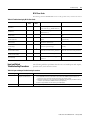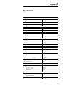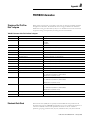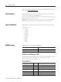
1
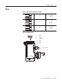
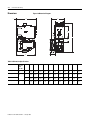
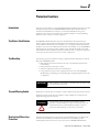
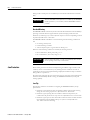
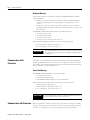
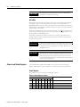
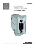
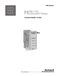
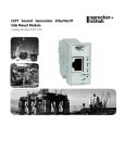
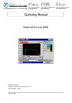
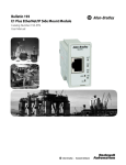
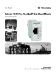
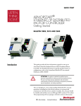
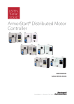
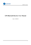
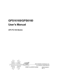
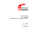
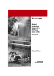
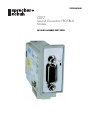
USER MANUAL
CEP7
Second Generation PROFIBUS
Module
CATALOG NUMBER CEP7-EPRB
Important User Information
Solid state equipment has operational characteristics differing from those of electromechanical
equipment. Safety Guidelines for the Application, Installation and Maintenance of Solid State Controls
(Publication SGI-1.1 available from your local Rockwell Automation sales office or online at
http://www.ab.com/manuals/gi) describes some important differences between solid state
equipment and hard-wired electromechanical devices. Because of this difference, and also
because of the wide variety of uses for solid state equipment, all persons responsible for
applying this equipment must satisfy themselves that each intended application of this
equipment is acceptable.
In no event will Rockwell Automation, Inc. be responsible or liable for indirect or consequential
damages resulting from the use or application of this equipment.
The examples and diagrams in this manual are included solely for illustrative purposes. Because
of the many variables and requirements associated with any particular installation, Rockwell
Automation, Inc. cannot assume responsibility or liability for actual use based on the examples
and diagrams.
No patent liability is assumed by Rockwell Automation, Inc. with respect to use of information,
circuits, equipment, or software described in this manual.
Reproduction of the contents of this manual, in whole or in part, without written permission of
Rockwell Automation, Inc. is prohibited.
Throughout this manual, when necessary we use notes to make you aware of safety
considerations.
WARNING
IMPORTANT
ATTENTION
Identifies information about practices or circumstances that can
cause an explosion in a hazardous environment, which may lead
to personal injury or death, property damage, or economic loss.
Identifies information that is critical for successful application
and understanding of the product.
Identifies information about practices or circumstances that can lead to
personal injury or death, property damage, or economic loss. Attentions
help you:
• identify a hazard
• avoid a hazard
• recognize the consequence
SHOCK HAZARD
Labels may be located on or inside the equipment (e.g., drive or
motor) to alert people that dangerous voltage may be present.
BURN HAZARD
Labels may be located on or inside the equipment (e.g., drive or
motor) to alert people that surfaces may be dangerous
temperatures.
Table of Contents
Chapter 1 Installation and Wiring
Introduction . . . . . . . . . . . . . . . . . . . . . . . . . . . . . . . . . . . . . . . . . . . . .
Features. . . . . . . . . . . . . . . . . . . . . . . . . . . . . . . . . . . . . . . . . . . . . . . . .
Installation . . . . . . . . . . . . . . . . . . . . . . . . . . . . . . . . . . . . . . . . . . . . . .
Wiring . . . . . . . . . . . . . . . . . . . . . . . . . . . . . . . . . . . . . . . . . . . . . . . . . .
Dimensions. . . . . . . . . . . . . . . . . . . . . . . . . . . . . . . . . . . . . . . . . . . . . .
1-1
1-3
1-4
1-5
1-6
Chapter 2 Protection Functions
Introduction . . . . . . . . . . . . . . . . . . . . . . . . . . . . . . . . . . . . . . . . . . . . .
Trip Status / Identification . . . . . . . . . . . . . . . . . . . . . . . . . . . . . . . . .
Trip Resetting . . . . . . . . . . . . . . . . . . . . . . . . . . . . . . . . . . . . . . . . . . . .
Trip and Warning Enable . . . . . . . . . . . . . . . . . . . . . . . . . . . . . . . . . .
Overload and Phase Loss Protection . . . . . . . . . . . . . . . . . . . . . . . . .
Overload Warning . . . . . . . . . . . . . . . . . . . . . . . . . . . . . . . . . . . . .
Jam Protection . . . . . . . . . . . . . . . . . . . . . . . . . . . . . . . . . . . . . . . . . . .
Jam Trip . . . . . . . . . . . . . . . . . . . . . . . . . . . . . . . . . . . . . . . . . . . . .
Jam Warning. . . . . . . . . . . . . . . . . . . . . . . . . . . . . . . . . . . . . . . . . .
Underload Protection. . . . . . . . . . . . . . . . . . . . . . . . . . . . . . . . . . . . . .
Underload Warning . . . . . . . . . . . . . . . . . . . . . . . . . . . . . . . . . . . .
Communication Fault Protection . . . . . . . . . . . . . . . . . . . . . . . . . . . .
Comm Fault Warning . . . . . . . . . . . . . . . . . . . . . . . . . . . . . . . . . .
Communication Idle Protection . . . . . . . . . . . . . . . . . . . . . . . . . . . . .
Comm Idle Warning . . . . . . . . . . . . . . . . . . . . . . . . . . . . . . . . . . .
2-1
2-1
2-1
2-1
2-2
2-2
2-3
2-3
2-4
2-4
2-5
2-5
2-5
2-6
2-6
Chapter 3 PROFIBUS Configuration
Introduction . . . . . . . . . . . . . . . . . . . . . . . . . . . . . . . . . . . . . . . . . . . . . 3-1
Acyclic Parameter Access (DP-V1). . . . . . . . . . . . . . . . . . . . . . . . 3-1
Cyclic Parameter Access (DP-V0). . . . . . . . . . . . . . . . . . . . . . . . . 3-2
Initial Data . . . . . . . . . . . . . . . . . . . . . . . . . . . . . . . . . . . . . . . . . . . 3-3
Control- and Status Registers . . . . . . . . . . . . . . . . . . . . . . . . . . . . . . . 3-4
Control Register . . . . . . . . . . . . . . . . . . . . . . . . . . . . . . . . . . . . . . . 3-4
Status Register . . . . . . . . . . . . . . . . . . . . . . . . . . . . . . . . . . . . . . . . 3-5
Parameter Programming . . . . . . . . . . . . . . . . . . . . . . . . . . . . . . . . . . . 3-6
Program Lock . . . . . . . . . . . . . . . . . . . . . . . . . . . . . . . . . . . . . . . . 3-6
Resetting to the Factory Default Values . . . . . . . . . . . . . . . . . . . . 3-6
Parameter Group Listing . . . . . . . . . . . . . . . . . . . . . . . . . . . . . . . . 3-7
Monitor Group . . . . . . . . . . . . . . . . . . . . . . . . . . . . . . . . . . . . . . . 3-8
Advanced Setup Group . . . . . . . . . . . . . . . . . . . . . . . . . . . . . . . . 3-11
Reset/Lock Group. . . . . . . . . . . . . . . . . . . . . . . . . . . . . . . . . . . . 3-14
I/O Setup Group. . . . . . . . . . . . . . . . . . . . . . . . . . . . . . . . . . . . . 3-15
Trip History Group . . . . . . . . . . . . . . . . . . . . . . . . . . . . . . . . . . . 3-17
PROFIBUS Setup Group . . . . . . . . . . . . . . . . . . . . . . . . . . . . . . 3-18
iii
Publication CEP7-UM010A-EN-P – January 2008
iv
Chapter 4 Troubleshooting
Introduction . . . . . . . . . . . . . . . . . . . . . . . . . . . . . . . . . . . . . . . . . . . . .
PROFIBUS Modes of Operation . . . . . . . . . . . . . . . . . . . . . . . . . . . .
Power-Up Mode . . . . . . . . . . . . . . . . . . . . . . . . . . . . . . . . . . . . . .
Run Mode. . . . . . . . . . . . . . . . . . . . . . . . . . . . . . . . . . . . . . . . . . . .
Configuration Error Mode . . . . . . . . . . . . . . . . . . . . . . . . . . . . . .
Fatal Error Mode . . . . . . . . . . . . . . . . . . . . . . . . . . . . . . . . . . . . . .
PROFIBUS Troubleshooting Procedures . . . . . . . . . . . . . . . . . . . . .
Network Status LED . . . . . . . . . . . . . . . . . . . . . . . . . . . . . . . . . . .
DP-V1 Error Codes. . . . . . . . . . . . . . . . . . . . . . . . . . . . . . . . . . . .
Input and Output Troubleshooting Procedures. . . . . . . . . . . . . . . . .
Trip and Warning Troubleshooting Procedures. . . . . . . . . . . . . . . . .
Appendix A - Specifications
. . . . . . . . . . . . . . . . . . . . . . . . . . . . . . . . . . . . . . . . . . . . . . . . . . . . . . . A-1
Appendix B PROFIBUS Information
Structure of the "Set Prm Data"-telegram . . . . . . . . . . . . . . . . . . . . . B-2
Electronic Data Sheet . . . . . . . . . . . . . . . . . . . . . . . . . . . . . . . . . . . . . B-3
Set Slave Address . . . . . . . . . . . . . . . . . . . . . . . . . . . . . . . . . . . . . . . . . B-3
Supported Baud Rates . . . . . . . . . . . . . . . . . . . . . . . . . . . . . . . . . . . . . B-3
PROIFIBUS Identity . . . . . . . . . . . . . . . . . . . . . . . . . . . . . . . . . . . . . . B-4
Identification and Maintenance (I&M) . . . . . . . . . . . . . . . . . . . . . B-4
Publication CEP7-UM010A-EN-P – January 2008
4-1
4-2
4-2
4-2
4-3
4-3
4-4
4-4
4-5
4-6
4-8
Chapter
1
Installation and Wiring
Introduction
The purpose of this chapter is to provide the necessary instructions to successfully install a
CEP7-EPRB PROFIBUS Module to an CEP7 Second Generation Overload Relay and properly
connect to a PROFIBUS network.
ATTENTION
ATTENTION
ATTENTION
ATTENTION
ATTENTION
ATTENTION
1
To prevent electrical shock, disconnect from power source before
installing or servicing. Install in suitable enclosure. Keep free from
contaminants.
The side mount module contains ESD (electrostatic discharge) sensitive
parts and assemblies. Static control precautions are required when
installing, testing, servicing, or repairing this assembly. Component
damage may result if ESD control procedures are not followed. If you
are not familiar with static control procedures, refer to Rockwell
Automation publication 8000-4.5.2, “Guarding Against Electrostatic
Damage”, or any other applicable ESD protection handbook.
The purpose of this document is to serve as a guide for proper
installation. The National Electrical Code and any other governing
regional or local code will take precedence. Rockwell Automation cannot
assume responsibility for the compliance or proper installation of the
side mount module or associated equipment. A hazard of personal injury
and/or equipment damage exists if codes are ignored during installation.
An incorrectly applied or installed side mount module can result in
damage to the components or reduction in product life. Wiring or
application errors such as supplying incorrect or inadequate supply
voltage, or operating/storing in excessive ambient temperatures may
result in malfunction of the product.
Only personnel familiar with the side mount module and associated
machinery should plan to install, set up, and maintain the system. Failure
to comply may result in personal injury and/or equipment damage.
This is a Class A product. In a domestic environment, this product may
cause radio interference, in which case, the user may be required to take
adequate measures.
Publication CEP7-UM010A-EN-P – January 2008
1-2
Installation and Wiring
Features
Figure 1.1 Features
Network Status LED
PROFIBUS Connector
Power Supply Connector
I/O Connector
Installation
Figure 1.2 Installation [1]
Figure 1.3 Installation [2]
#2 Driver
0.7 - 1.1 N . m
(6 - 10 lb-in)
Figure 1.4 Installation [3]
7mm
(.28 in)
0.6mm X 3.5mm Blade
(.02 in X .14 in Blade)
0.5 - 0.6 N . m
(4.4 - 5.3 lb-in)
Publication CEP7-UM010A-EN-P – January 2008
Installation and Wiring
1-3
Wiring
Table 1.1 Wire and Size Torque Specifications
1X
2X
24…12 AWG
24…16 AWG
5 lb.-in
1X
2X
0.2…2.5 mm2
0.25…1 mm2
0.55 N•m
1X
2X
0.2…2.5 mm2
0.2…1 mm2
0.55 N•m
Figure 1.5 Wiring Diagram
6
NC
NC
B-Line
RTS
GND BUS
+5V BUS OUT
NC
A-Line
NC
SHIELD
A2 ( -)
OUTA
(B300)
(20.4 - 26.4 VDC)
3
A1 (+)
SSV
2
9
1.
2.
3.
4.
5.
6.
7.
8.
9.
Housing
1
IN2
13 14 1
5
IN1
Publication CEP7-UM010A-EN-P – January 2008
1-4
Installation and Wiring
Dimensions
Figure 1.6 Dimension Diagram
J
H
A
F
G
E
K
B
D
L
C
Table 1.2 Dimension Specifications
Contactor Cat. No.
CEP7
Second
Gen.
Cat. No.
CA7-9, -12, -16, -23
CEP7-EE_
B
CA7-30, -37
CEP7-EE_
D
CA7-43
CA7-60, -72, -85
CEP7-EE_
E
A
B
C
D
E
F
G
H
J
K
L
mm
(in)
67
(2.64)
148
(5.83)
85.2
(3.35)
24.5
(.96)
13.9
(.55)
35
(1.38)
60
(2.36)
86.5
(3.40)
2
(.08)
4.5
(.17)
22
(.86)
mm
(in)
67
(2.64)
148
(5.83)
101.2
(3.98)
24.5
(.96)
13.9
(.55)
35
(1.38)
60
(2.36)
104
(4.09)
2
(.08)
4.5
(.17)
22
(.86)
mm
(in)
71.5
(2.82)
148
(5.83)
101.2
(3.98)
24.5
(.96)
18.4
(.74)
45
(1.77)
60
(2.36)
104
(4.09)
2
(.08)
4.5
(.17)
22
(.86)
mm
(in)
94
(3.70)
191.6
(7.54)
120.4
(4.74)
29
(1.14)
23.8
(.94)
55
(2.16)
100
(3.94)
126
(4.94)
2
(.08)
5.4
(.21)
22
(.86)
Publication CEP7-UM010A-EN-P – January 2008
Chapter
2
Protection Functions
Introduction
The purpose of this chapter is to provide detailed information regarding the protective trip and
warning functions that the CEP7-EPRB PROFIBUS Module adds to the CEP7 Second
Generation Overload Relay. In this chapter, you will find considerable mention given to
parameters as they relate to these functions. For complete descriptions of the programming
parameters, refer to Chapter 3 - Profibus Configuration.
Trip Status / Identification
The PROFIBUS Module determines trip status and identification through monitoring of
reference signals inside the CEP7 Second Generation Overload Relay. On power-up, it assumes
that the CEP7 Second Generation Overload Relay is in a non-tripped condition. For definitive
feedback on trip status of the CEP7 Second Generation Overload Relay, one of the PROFIBUS
module inputs may be wired to the N.O. auxiliary contact (terminals 97 and 98) of the CEP7
Second Generation Overload Relay. Parameters 28 and 29 are used to configure the assignment
of the inputs. For this function, use the “OL Contact” configuration.
Trip Resetting
The following options are available for resetting a tripped CEP7 Second Generation Overload
Relay with a PROFIBUS module:
• Blue mechanical reset button located on the front of the CEP7 Second Generation
Overload Relay
• Setting Parameter 19, Trip Reset, to “Reset”
• Setting the "Trip Reset"-bit bit in the Control Register
• Using a push button (N.O. contact configuration) wired to one of the PROFIBUS
Module inputs, programming the corresponding input assignment parameter (28 or 29)
to “Trip Reset”
IMPORTANT
Trip and Warning Enable
Setting parameter 11, Reset Mode, to “Automatic” does not result in other
reset commands being ignored.
Parameter 8, Trip Enable, allows the installer to enable or disable the jam trip protective function.
Parameter 9, Warning Enable, allows the installer to enable or disable the overload, jam and
underload warning protective functions.
ATTENTION
Overload and Phase Loss
Protection
1
The Trip Enable settings should not be altered during machine
operation, as unexpected behavior could occur. This may result in an
unintended actuation of controlled industrial equipment, with the
potential for machine damage or serious injury to personnel.
Thermal overload and phase loss trip protection is provided exclusively by the CEP7 Second
Generation Overload Relay. The CEP7 Second Generation Overload Relay provides
uninterrupted protection to the motor, even in the event of a PROFIBUS Module failure.
Publication CEP7-UM010A-EN-P – January 2008
2-2
Protection Functions
Settings for FLA and trip class are found directly on the CEP7 Second Generation Overload
Relay.
IMPORTANT
The reset mode DIP switch adjustment is overridden by the PROFIBUS
module parameter 11, OL Reset Mode, while the PROFIBUS module is
powered.
Overload Warning
The PROFIBUS Module continuously monitors the CEP7 Second Generation Overload Relay's
percentage of thermal utilization signal. Parameter 2,%Therm Utilized, provides this value.
Parameter 12, OL Warning Level, is used to adjust the setpoint to alert for an impending overload
trip and is adjustable from 0…100% TCU.
The PROFIBUS Module will indicate an overload warning if all the following conditions are
met:
• No warning currently exists
• Overload warning is enabled
• %Therm Utilized is equal to or greater than OL Warning Level
When the overload warning conditions are satisfied, the following will occur:
• Bit 0 in Parameter 4, Warning Status, will go to “1”
• Bit 1 of Parameter 5, Device Status, will go to “1”
IMPORTANT
Jam Protection
%Therm Utilized will stabilize at a value of approximately 88% with the
motor operating continuously at rated current.
Motor current greater than the motor's nameplate rating can indicate a high overload or stall
condition, such as an overloaded conveyor or jammed gear. These conditions can result in
overheating of the motor, and equipment damage. Rapid jam fault detection helps to minimize
damage and loss of production.
By continuously monitoring the motor current level signal as a percentage of the CEP7 Second
Generation Overload Relay's dial FLA setting, the PROFIBUS module allows jam trip and
warning capability.
Jam Trip
The following parameters are available for configuring the PROFIBUS Module's jam trip
performance:
• Parameter 13, Jam Inhibit Time, allows the installer to inhibit a jam trip from occurring
during the motor starting sequence. It is adjustable from 0…250 seconds.
• Parameter 14, Jam Trip Delay, allows the installer to define the time period a jam
condition must be present before a trip occurs. It is adjustable from 0.5…25.0 seconds.
• Parameter 15, Jam Trip Level, allows the installer to define the current at which the CEP7
Second Generation Overload Relay will trip on a jam. It is user-adjustable from
150…600% of the FLA dial setting.
Publication CEP7-UM010A-EN-P – January 2008
Protection Functions
2-3
The PROFIBUS Module will command the CEP7 Second Generation Overload Relay to trip if
all the following conditions are met:
•
•
•
•
No trip currently exists
Jam Protection is enabled
Jam Inhibit Time has expired
The motor current is greater than the Jam Trip Level for a time period greater than the
Jam Trip Delay
When the conditions for a jam trip are satisfied, the following will occur:
•
•
•
•
Bit 2 in Parameter 3, Trip Status, will go to “1”
Bit 0 in Parameter 5, Device Status, will go to “1”
The CEP7 Second Generation Overload Relay's trip relay contacts (95 and 96) will open
Out A will be placed in their Protection Fault State (if so programmed)
IMPORTANT
IMPORTANT
The Protection Fault State of OUT A is defined by parameter 22
(OUTA Pr FltState) and parameter 23 (OUTA Pr FltValue).
The jam inhibit timer starts after the load current transitions from 0 A to
30% FLA. The PROFIBUS Module does not begin monitoring for a jam
condition until the Jam Inhibit Time expires.
Jam Warning
Parameter 16, Jam Warn Level, allows the installer to define the current at which the PROFIBUS
Module will indicate a warning. It is user-adjustable from 100…600% FLA.
The PROFIBUS Module will indicate a Jam warning if:
•
•
•
•
No warning currently exists
Jam Warning is enabled
Jam Inhibit Time has expired
The motor current is equal to or greater than the Jam Warn Level
When the Jam Warning conditions are satisfied, the following will occur:
• Bit 2 in Parameter 4, Warning Status, will go to “1”
• Bit 1 in Parameter 5, Device Status, will go to “1”
IMPORTANT
Underload Protection
The Jam Warning function does not include a time delay feature. Once
the Jam Inhibit Time has expired, the Jam Warning indication is
instantaneous.
Motor current less than a specific level may indicate a mechanical malfunction in the installation,
such as a torn conveyor belt, damaged fan blade, broken shaft, or worn tool. Such conditions
may not harm the motor, however, rapid detection may help to minimize equipment damage
and loss of production.
Publication CEP7-UM010A-EN-P – January 2008
2-4
Protection Functions
Underload Warning
The following parameters are available for configuring the PROFIBUS Module's underload
warning performance:
• Parameter 17, UL Inhibit Time, allows the installer to inhibit an underload indication
from occurring during the motor starting sequence. It is adjustable from 0…250
seconds.
• Parameter 18, UL Warn Level, allows the installer to define the current at which the
PROFIBUS Module will indicate a warning. It is user-adjustable from 30…100% of the
FLA dial setting.
The PROFIBUS Module will immediately indicate an Underload warning if:
•
•
•
•
No warning currently exists
Underload Warning is enabled
UL Inhibit Time has expired
The motor current is less than the UL Warn Level
When the Underload Warning conditions are satisfied, the following will occur:
• Bit 3 in Parameter 4, Warning Status, will go to “1”
• Bit 1 of Parameter 5, Device Status, will go to “1”
IMPORTANT
Communication Fault
Protection
The Underload Warning function does not include a time delay feature.
Once the UL Inhibit Time has expired, the Underload warning indication
is instantaneous.
A disruption of the communication link between the CEP7 Second Generation PROFIBUS
Module and a PROFIBUS network can result in the loss of application control and/or critical
process diagnostic data. Rapid communication fault detection helps minimize potential damage
due to uncontrolled or unmonitored applications.
Comm Fault Warning
The PROFIBUS Module will indicate a Comm Fault warning if:
• No warning currently exists
• Comm Fault Warning is enabled
• The PROFIBUS Module experiences a loss of communication
When the Comm Fault warning conditions are satisfied, the following will occur:
• The Network Status LED will go out
• Bit 5 in Parameter 4, Warning Status, will go to “1”
• Bit 1 of Parameter 5, Device Status, will go to “1”
IMPORTANT
Communication Idle Protection
Publication CEP7-UM010A-EN-P – January 2008
The Comm Fault State of OUT A is defined by Parameter 24 (OUTA Pb
FltState) and parameter 25 (OUTA Pb FltValue).
When a programmable controller is placed into the program mode, the execution of its ladder
program is suspended, and any connected networks go to an idle state. If inadvertent, this can
result in the loss of application control and/or critical process diagnostic data. Rapid
Protection Functions
2-5
communication idle detection helps minimize the potential damage due to uncontrolled or
unmonitored applications.
Comm Idle Warning
The PROFIBUS Module will indicate a Comm Idle warning if:
• No warning currently exists
• Comm Idle Warning is enabled
• The PROFIBUS module is in idle (clear) mode
When the Comm Idle warning conditions are satisfied, the following will occur:
• Bit 6 in Parameter 4, Warning Status, will go to “1”
• Bit 1 in Parameter 5, Device Status, will go to “1”
IMPORTANT
The Comm Idle State of OUT A is defined by Parameter 26 (OUTA Pb
IdlState) and parameter 27 (OUTA Pb IdlValue).
Publication CEP7-UM010A-EN-P – January 2008
2-6
Protection Functions
Publication CEP7-UM010A-EN-P – January 2008
Chapter
3
PROFIBUS Configuration
Introduction
The PROFIBUS Module supports DP-V0 and DP-V1 communications. It is commissioned for
a PROFIBUS network using a GSD file which contains information about parameters, profiles,
I/O types, and sizes specific for this module. The GSD file for the CEP7-EPRB can be
dowloaded from http://www.ab.com/networks/gsd/.
Acyclic Parameter Access (DP-V1)
The preferred way of accessing device parameters is by means of Acyclic (DP-V1) read- and
write services. When accessed acyclically, parameters are addressed by their corresponding
Index (index equals parameter number). Note that due to technical reasons imposed by the
PROFIBUS networking system, it is required to map at least one byte of Cyclic I/O in either
direction. Any parameter can be used for this purpose.
Note: The slot number is not significant (i.e. it’s ignored by the module)
IMPORTANT
IMPORTANT
IMPORTANT
Write requests towards writeable parameters will automatically cause the
corresponding setting to be saved in non volatile memory. For
consistency reasons, all parameters mapped as Cyclic I/O will be
read-only when accessed acyclically.
Changes made to parameter values will take effect immediately even
during a “running” status.
Parameter setting changes made in a PROFIBUS configuration tool do
not take effect in the PROFIBUS Module until the installer applies or
downloads the new settings to the device.
Cyclic Parameter Access (DP-V0)
All parameters can be accessed cyclically by adding the corresponding GSD-module to the
network configuration. GSD-modules can be added (i.e. mapped as Cyclic I/O) as needed, in
any order, with a few restrictions:
• At least one byte must be mapped as Cyclic I/O. This can either be device parameters or - the Control- and Status Registers.
• It is not permitted to map the same parameter to the Cyclic I/O configuration more
than once.
• Parameters mapped as Cyclic I/O cannot be written using Acyclic (DP-V1) services.
IMPORTANT
1
For technical reasons, writeable parameters mapped as Cyclic I/O will
not be saved automatically in non volatile memory. To save such
paramaters, a save operation must explicitly be triggered by means of a
bit in the Control Register.
Publication CEP7-UM010A-EN-P – January 2008
3-2
PROFIBUS Configuration
All changes made to parameter values, saved or not, will take effect
immediately even during Data Exchange.
IMPORTANT
Initial Data
During startup of the network, it is possible to load start-up values (loaded on each transition
from offline to online) for all writable parameters by means of the User Prm Data. The
PROFIBUS Module will use these settings provided that "Parameter Initialization" (User Prm
Data byte #3) is set as "Enabled". Note that this will result in any previous settings stored in non
volatile memory to be replaced.
Initial values supplied through the User Prm Data will only be used if all initial parameter values
are valid. In case an illegal initial parameter value is specified, an out-of-range parameter error
will be signalled to the PROFIBUS master.
The loading of initial data also includes the "Program Lock"-setting, which means that it is
possible to specify a default configuration during startup, which will then be protected from
write access during runtime.
Initial values supplied through the User Prm Data will only be used if all
initial parameter values are valid. In case an illegal initial parameter value
is specified, an out-of-range parameter error will be signalled to the
PROFIBUS master.
IMPORTANT
Special care has to be taken for parameters mapped as Cyclic I/O, since
their value may be overwritten during the first bus cycle. This can be
prevented using parameter 20 (Program Lock), however as soon as the
Program Lock is disabled, the value of these parameters will be replaced
by the corresponding I/O data.
IMPORTANT
Control- and Status Registers
A special GSD-module (labelled "193-EPRB") is used to house the Control- and Status
Registers. These registers controls- and reflects the overall status of the module respectively.
Control Register
The structure controls various aspects of the module as follows:
Table 3.1 Control Register contents
Bit
7
6
5
4
3
Function:
2
1
0
X
X
Trip Reset
X
X
Publication CEP7-UM010A-EN-P – January 2008
OutA
Save
X
X
X
X
Not Used
PROFIBUS Configuration
3-3
• Bit 0; OutA – Control of the Output relay. The bit is flank triggered, i.e. a state transition
from 0 to 1 or from 1 to 0 must be performed to change the state of the relay
• Bit 2; Trip Reset – Same functionality as parameter 19, Trip Reset. The bit is flank
triggered, i.e. a state transition from 0 to 1 must be performed to trigger a trip reset.
• Bit 6; Save – Used to trigger a save (to non-volatile memory) of parameter values of
parameters that are mapped as Cyclic I/O. The bit is flank triggered, i.e. a state transition
from 0 to 1 must be performed to trigger a save operation.
Status Register
The Status Register reflects the overall status of the module as follows:
Table 3.2 Status Register contents
Bit
7
6
5
4
3
Function:
2
1
0
X
X
X
X
X
X
X
X
Trip
Warning
OutA Stat
Not Used
Input 1
Input 2
Save Ready
Motor Curr.
• Bit 0
Trip – Same functionality as bit 0 in parameter 5, Device Status.
• Bit 1
Warning – Same functionality as bit 1 in parameter 5, Device Status.
• Bit 2
OutA Stat – Same functionality as bit 2 in parameter 5, Device Status.
• Bit 4
Input 1 – Same functionality as bit 3 in parameter 5, Device Status.
• Bit 5
Input 2 – Same functionality as bit 4 in parameter 5, Device Status.
• Bit 6
Save Ready – Used to indicate that a save of parameter values of parameters mapped as
Cyclic I/O has been performed. The bit can be cleared again by clearing the "Save"-bit
in the Control Register.
• Bit 7
Motor Current – Same functionality as bit 5 in parameter 5, Device Status.
Publication CEP7-UM010A-EN-P – January 2008
3-4
PROFIBUS Configuration
Parameter Programming
Program Lock
Parameter 20, Program Lock, provides a degree of security from having parameter settings
unintentionally altered when programmed to the “locked” setting.
If enabled, all parameters except Program Lock (20) are protected from acyclic (DP-V1) write
access, and any changes made to the value of parameters mapped as Cyclic I/O will be ignored.
The "Program Lock" parameter will, if mapped as Cyclic I/O, be processed prior to processing
other parameters mapped as Cyclic I/O. The loading of initial data is not affected by the
Program Lock.
Resetting to the Factory Default Values
Parameter 25, Set to Defaults, allows the installer to reset all parameter settings (including trip
logs) to the factory default values.
IMPORTANT
Resetting to factory default values also resets the node address of the
PROFIBUS module to its default value of 126.
Parameter Group Listing
The CEP7-EPRB PROFIBUS Module contains six parameter groups:
Table 3.3 Parameter Groups
Monitor parameters
Advanced Setup
Reset/Lock
I/O Setup
Trip History
PROFIBUS Setup
1 Average %FLA
8 Trip Enable
19 Trip Reset
22 OutA Pr FltState
30 Trip Log 0
35 SSA Node Address
2%Therm Utilized
9 Warning Enable
20 Program Lock
23 OutA Pr FltValue
31 Trip Log 1
3 Trip Status
10 Single/Three Ph
21 Set to Defaults
24 OutA Pb FltState
32 Trip Log 2
4 Warning Status
11 OL Reset Mode
25 OutA Pb FltValue
33 Trip Log 3
5 Device Status
12 OL Warning Level
26 OutA Pb IdlState
34 Trip Log 4
6 Firmware Revision
13 Jam Inhibit Time
27 OutA Pb IdlValue
7 Serial Number
14 Jam Trip Delay
28 IN1 Assignment
15 Jam Trip Level
29 IN2 Assignment
16 Jam Warn Level
17 UL Inhibit Time
18 UL Warn Level
Publication CEP7-UM010A-EN-P – January 2008
PROFIBUS Configuration
3-5
Monitor Group
Average %FLA
Index No.
1
This parameter reports the average motor current. The value is
reported as a percentage of motor rated current (dial setting on
the CEP7 Second Generation Overload Relay), and is reported in
increments of 5.
Access Rule
Read
14
13
12
11
10
9
8
X
X
X
X
X
14
13
12
11
10
9
8
0
Max. Value
1275
Default Value
None
2
Read
Size
1 byte
Group
Monitor
Units
%
Min. Value
0
Max. Value
100
Default Value
None
Trip Status
Index No.
3
This parameter provides trip identification.
1 = Trip
0 = No Trip
Access Rule
Read
7
X
Size
2 bytes
Group
Monitor
Units
—
Min. Value
—
Max. Value
—
Default Value
None
Function:
6
5
4
3
2
1
0
X
X
X
Overload
Phase Loss
Jam
X
Not Used
Warning Status
Index No.
4
This parameter provides warning identification
1 = Warning
0 = No Warning
Access Rule
Read
Bit
15
%FLA
Min. Value
Index No.
X
X
Units
Access Rule
X
X
Monitor
This parameter reports the percent thermal utilization of the
connected motor.
X
X
2 bytes
Group
% Therm Utilized
Bit
15
Size
7
Size
2 bytes
Group
Monitor
Units
—
Min. Value
—
Max. Value
—
Default Value
None
Function:
6
5
4
3
2
1
0
X
X
X
Overload
Not Used
Jam
Publication CEP7-UM010A-EN-P – January 2008
3-6
PROFIBUS Configuration
Bit
15
14
13
12
11
10
9
8
7
Function:
6
5
4
3
2
1
0
X
Underload
X
Not Used
X
Comm Fault
X
Comm Idle
X
X
X
X
X
X
X
X
Nonvolatile Memory Fault
X
Not Used
Device Status
Index No.
5
This parameter provides status information related to the CEP7
Second Generation Overload Relay and the PROFIBUS Module.
1 = On or Present
0 = Off or Not Present
Access Rule
Read
Bit
15
14
13
12
11
10
9
8
7
6
5
4
3
2
1
X
X
X
X
X
X
X
X
X
Publication CEP7-UM010A-EN-P – January 2008
X
X
Monitor
Units
—
Min. Value
—
Max. Value
—
Default Value
None
0
X
X
2 bytes
Group
Function:
X
X
Size
X
Trip
Warning
Out A
In 1
In 2
Motor Current
Not Used
Firmware Revision
Index No.
6
This parameter reports the firmware revision of the PROFIBUS
Module.
Format:
0x0107 equals version 1.07
Access Rule
Read
Size
2 bytes
Group
Monitor
Units
—
Min. Value
0
Max. Value
65535
Default Value
None
Serial Number
Index No.
7
This parameter reports the serial number assigned during
production of the PROFIBUS Module.
Access Rule
Read
Size
4 bytes
Group
Monitor
Units
—
Min. Value
0
Max. Value
0xFFFFFFFF
Default Value
None
PROFIBUS Configuration
3-7
Advanced Setup Group
Trip Enable
Index No.
8
This parameter allows the installer to enable or
disable the Jam Trip function
1 = Enabled
0 = Disabled
Access Rule
Read/Write
Size
2 bytes
Group
Advanced Setup
Units
—
Min. Value
0000000000000000
Max. Value
0000000000000100
Default Value
0000000000000000
Bit
15
14
13
12
11
10
9
8
7
Function:
6
5
4
3
2
1
0
X
Not Used
X
Not Used
X
X
X
X
X
X
X
X
X
X
X
X
X
Jam
X
Not Used
Warning Enable
Index No.
9
This parameter allows the installer to enable or
disable the warning functions separately. All
warning functions are disabled from the
factory.
1 = Enabled
0 = Disabled
Access Rule
Read/Write
Size
2 bytes
Group
Advanced Setup
Units
—
Min. Value
0000000000000000
Max. Value
0000000001101101
Default Value
0000000000000000
Bit
15
14
13
12
11
10
9
8
7
Function:
6
5
4
3
2
1
0
X
Overload
X
Not Used
X
Jam
X
Underload
X
Not Used
X
Comm Fault
X
X
X
X
X
X
X
X
X
Comm Idle
X
Not Used
Single/Three Ph
Index No.
10
This parameter configures the PROFIBUS Module for singleor three-phase application. This parameter should be set to
“Single Phase" when CEP7S devices are employed.
Access Rule
Read/Write
Size
1 byte
Group
Advanced Setup
Units
—
Min. Value
0 = Single-Phase
Max. Value
1 = Three-Phase
Default Value
1
Publication CEP7-UM010A-EN-P – January 2008
3-8
PROFIBUS Configuration
Publication CEP7-UM010A-EN-P – January 2008
OL Reset Mode
Index No.
11
This parameter defines whether a trip can be automatically
or manually reset. This setting overrides the CEP7 Second
Generation DIP switch adjustment while the PROFIBUS
Module is powered. Note, however, that the CEP7 Second
Generation manual reset button, accessible at the front, is
always active.
Access Rule
Read/Write
Size
1 byte
Group
Advanced Setup
Units
—
Min. Value
0 = Manual
Max. Value
1 = Automatic
Default Value
0
OL Warning Level
Index No.
12
This parameter sets the overload warning level.
Access Rule
Read/Write
Size
1 byte
Group
Advanced Setup
Units
% Thermal Utilization
Min. Value
0
Max. Value
100
Default Value
90
Jam Inhibit Time
Index No.
13
This parameter defines the amount of time for which jam
detection is inhibited during a motor starting sequence.
Access Rule
Read/Write
Size
1 byte
Group
Advanced Setup
Units
Seconds
Min. Value
0
Max. Value
250
Default Value
10
Jam Trip Delay
Index No.
14
This parameter allows the installer to program a time
duration for which a jam condition must exist at the
programmed level prior to the device tripping.
Access Rule
Read/Write
Size
1 byte
Group
Advanced Setup
Units
Seconds
Min. Value
0.5
Max. Value
25.0
Default Value
5.0
Jam Trip Level
Index No.
15
This parameter sets the jam trip level.
Access Rule
Read/Write
Size
2 bytes
Group
Advanced Setup
Units
% FLA
Min. Value
150
Max. Value
600
Default Value
250
PROFIBUS Configuration
Jam Warn Level
Index No.
16
This parameter sets the jam warning level.
Access Rule
Read/Write
Size
2 bytes
Group
Advanced Setup
Units
% FLA
Min. Value
100
Max. Value
600
Default Value
150
UL Inhibit Time
Index No.
17
This parameter defines the amount of time for which
underload detection is inhibited during a motor starting
sequence.
Access Rule
Read/Write
Size
1 byte
Group
Advanced Setup
Units
Seconds
Min. Value
0
Max. Value
250
Default Value
10
UL Warn Level
Index No.
18
This parameter sets the underload warning level.
Access Rule
Read/Write
Size
1 byte
Group
Advanced Setup
Units
% FLA
Min. Value
30
Max. Value
100
Default Value
70
3-9
Reset/Lock Group
Trip Reset
Index No.
19
This parameter provides the user with the capability of
resetting a trip over the PROFIBUS network. After a trip is
reset, the parameter automatically returns to a “Ready”
state.
Access Rule
Read/Write
Size
1 byte
Group
Reset/Lock
Units
—
Min. Value
0 = Ready
Max. Value
1 = Reset Trip
Default Value
0
Program Lock
Index No.
20
This parameter prohibits the device parameters from being
altered when set to “Locked”. It must be set to “Unlocked”
to allow parameter modification.
Access Rule
Read/Set
Size
1 byte
Group
Reset/Lock
Units
—
Min. Value
0 = Unlocked
Max. Value
1 = Locked
Default Value
0
Publication CEP7-UM010A-EN-P – January 2008
3-10
PROFIBUS Configuration
Set To Defaults
Index No.
21
This parameter allows the user to reset the parameter
settings to the factory default values. After parameter
values have been reset to the factory default settings, the
parameter automatically returns to a “Ready” state.
Access Rule
Read/Write
Size
1 byte
Group
Reset/Lock
Units
—
Min. Value
0 = Ready
Max. Value
1 = Reset Defaults
Default Value
0
I/O Setup Group
Publication CEP7-UM010A-EN-P – January 2008
OutA Pr FltState
Index No.
22
This parameter, in conjunction with parameter 23,
defines how Output A will respond when a trip occurs.
When set to “1”, Output A will continue to operate as
commanded via the network. When set to “0”, Output A
will open or close as determined by the setting of
parameter 23.
Access Rule
Read/Write
Size
1 byte
Group
I/O Setup
Units
—
Min. Value
0 = Go To FltValue (#23)
Max. Value
1 = Ignore Fault
Default Value
0
OutA Pr FltValue
Index No.
23
This parameter determines the state that Output A assumes
when a trip occurs and Parameter 22 is set to “0”.
Access Rule
Read/Write
Size
1 byte
Group
I/O Setup
Units
—
Min. Value
0 = Open
Max. Value
1 = closed
Default Value
0
OutA Pb FltState
Index No.
This parameter, in conjunction with Parameter 25,
defines how Output A will respond when a PROFIBUS
network fault occurs. When set to “1”, Output A will
hold the state prior to PROFIBUS fault occurrence. When
set to “0”, Output A will open or close as determined by
the setting of Parameter 25.
Access Rule
24
Read/Write
Size
1 byte
Group
I/O Setup
Units
—
Min. Value
0 = Go To FltValue (#25)
Max. Value
1 = Hold Last State
Default Value
0
OutA Pb FltValue
Index No.
25
This parameter determines the state that Output A assumes
when a PROFIBUS network fault occurs and Parameter 24 is
set to “0”.
Access Rule
Read/Write
Size
1 byte
Group
I/O Setup
Units
—
Min. Value
0 = Open
Max. Value
1 = Closed
Default Value
0
PROFIBUS Configuration
OutA Pb IdlState
Index No.
26
This parameter, in conjunction with parameter 27,
defines how Output A will respond when the PROFIBUS
network is idle. When set to “1”, Output A will hold the
state prior to PROFIBUS fault occurrence. When set to
“0”, Output A will open or close as determined by the
setting in Parameter 27. The Pb Flt parameters
supersede the Pb Idl parameters.
Access Rule
Read/Write
Size
1 byte
Group
I/O Setup
Units
—
Min. Value
0 = Go To IdlValue (#27)
Max. Value
1 = Hold Last State
Default Value
0
OutA Pb IdlValue
Index No.
27
This parameter determines the state that Output A assumes
when the network is idle and parameter 26 is set to “0”.
Access Rule
Read/Write
Size
1 byte
Group
I/O Setup
Units
—
Min. Value
0 = Open
Max. Value
1 = Closed
Default Value
0
IN1 Assignment
Index No.
28
This parameter allows the user to assign a specific function
to the discrete IN1 input.
Access Rule
Read/Write
Size
1 byte
Group
I/O Setup
Units
—
Min. Value
Max. Value
0 = Normal
1 = Trip reset
2 = OL Contact
Default Value
0
IN2 Assignment
Index No.
29
This parameter allows the user to assign a specific function
to the discrete IN2 inputs.
Access Rule
Read/Write
Size
1 byte
Group
I/O Setup
Units
—
Min. Value
Max Value
0 = Normal
1 = Trip Reset
2 = OL Contact
Default Value
0
Trip Log 0
Index No.
30
This parameter records the latest trip.
Access Rule
Read
Size
2 byte
3-11
Trip History Group
Group
Trip History
Units
—
Min. Value
See Trip Status table
Max. Value
See Trip Status table
Default Value
None
Publication CEP7-UM010A-EN-P – January 2008
3-12
PROFIBUS Configuration
Trip Log 1
Index No.
31
This parameter records the trip previous to Trip Log 0.
Access Rule
Read
Size
2 bytes
Group
Trip History
Units
—
Min. Value
See Trip Status table
Max. Value
See Trip Status table
Default Value
None
Trip Log 2
Index No.
32
This parameter records the trip previous to Trip Log 1.
Access Rule
Read
Size
2 bytes
Group
Trip History
Units
—
Min. Value
See Trip Status table
Max. Value
See Trip Status table
Default Value
None
Trip Log 3
Index No.
33
This parameter records the trip previous to Trip Log 2.
Access Rule
Read
Size
2 bytes
Group
Trip History
Units
—
Min. Value
See Trip Status table
Max. Value
See Trip Status table
Default Value
None
Trip Log 4
Index No.
34
This parameter records the trip previous to Trip Log 3.
Access Rule
Read
Size
2 bytes
Group
Trip History
Units
—
Min. Value
See Trip Status table
Max. Value
See Trip Status table
Default Value
None
SSA Node Address
Index No.
35
This parameter holds the latest node address sent by the Set
Slave Address telegram. This is the node address the slave
will start up with after the next power-cycle.
NOTE: This parameter is added to provide a way to change
the node address in the case that the master does not
support the SSA service.
Normally this parameter does not need to be used.
Access Rule
Read/Write
PROFIBUS Setup Group
Publication CEP7-UM010A-EN-P – January 2008
Size
1 byte
Group
PROFIBUS Setup
Units
—
Min. Value
0
Max. Value
126
Default Value
126
Chapter
4
Troubleshooting
Introduction
The purpose of this chapter is to assist in troubleshooting the CEP7 Second Generation
PROFIBUS module.
ATTENTION
ATTENTION
PROFIBUS Modes of Operation
Servicing energized industrial control equipment can be hazardous.
Electrical shock, burns, or unintentional actuation of controlled
industrial equipment may cause death or serious injury. For safety of
maintenance personnel, as well as other who may be exposed to
electrical hazards associated with the maintenance activities, follow the
local safety-related work practices (for example, the NFPS 70W, Part II,
Electrical Safety for Employee Workplaces, in the United States) when working
on or near energized equipment. maintenance personnel must be trained
in the safety practices, procedures, and requirements that pertain to their
respective job assignments. Do not work alone on energized equipment.
Do not attempt to defeat or override fault circuits. The cause of a fault
indication must be determined and corrected before attempting
operation. Failure to correct a control system or mechanical malfunction
may result in personal injury and/or equipment damage due to
uncontrolled machine system operation.
The CEP7 Second Generation PROFIBUS Module has four PROFIBUS modes of operation:
Power-up Mode, Run Mode, and Configuration Error Mode.
Power-Up Mode
During power-Up Mode, the NETWORK STATUS LED should flash green for approximately
1/4 second, then red for 1/4 second.
IMPORTANT
The CEP7 Second Generation PROFIBUS Module protection functions
are still operational even without an established network connection.
If the power-up is successful, the overload relay will enter Run Mode.
Run Mode
In Run Mode, the CEP7 Second Generation PROFIBUS Module will operate as a slave device to
a master device. The NETWORK STATUS LED will blink green if the PROFIBUS interface is
in idle mode. When on-line, the NETWORK STATUS LED will turn solid green.
In the Run Mode, the CEP7 Second Generation PROFIBUS Module will:
• Exchange Cyclic I/O with a master on the PROFIBUS network.
• Respond to Acyclic (DP-V1) read- and write- services
If a communication error is detected, the CEP7 Second Generation PROFIBUS Module will
either enter the Configuration Error Mode.
1
Publication CEP7-UM010A-EN-P – January 2008
4-2
Troubleshooting
Configuration Error Mode
In this mode, the CEP7 Second Generation PROFIBUS Module’s NETWORK STATUS LED
flashes red at 1Hz.
Error Type
Description
LED State
Configuration Error
Configuration fault or parameter fault
Flashing Red (1Hz)
Fatal Error Mode
In Fatal Error Mode, the CEP7 Second Generation PROFIBUS Module’s NETWORK STATUS
LED turns solid red. The overload relay continues in this state as long as the device is powered.
The only way to recover from this mode is to power-cycle the module.
Error Type
Description
LED State
Fatal
Power-up initialization failure
Solid Red
Fatal communication error
PROFIBUS Troubleshooting
Procedures
Network Status LED
The following table identifies possible causes and corrective actions when troubleshooting
PROFIBUS-related failures using the NETWORK STATUS LED.
Table 4.4 Troubleshooting using NETWORK STATUS LED
Color
State
Possible Cause
1. The CEP7 Second Generation PROFIBUS Module is not
receiving power at the PROFIBUS connector.
2. The module is off-line
Corrective Action
None
-
Green
Red
Off
Flashing (once)
Normal operating state; The CEP7 Second Generation
PROFIBUS Module is performing internal initialization
procedures.
No action required; the Network Status LED flashes
green-red-off during a normal power-up sequence.
Green
Flashing (1Hz)
Normal operating state; CEP7 Second Generation PROFIBUS
Module is in idle state.
No action required.
Green
Solid
Normal operating state; the CEP7 Second Generation PROFIBUS
Module is on-line.
No action required.
Red
Flashing (1Hz)
Red
Solid
A fatal error has occurred in the module.
Cycle power to the unit and network. If the fault still exists,
replace unit.
Red
Lit 1s then off
Major internal fault
Cycle power to the unit and network. If the fault still exists,
replace unit. If the problem persists, contact technical support.
1. Configuration fault
2. Parameter fault
Publication CEP7-UM010A-EN-P – January 2008
Check power and PROFIBUS cable connections.
Correct the configuration and restart the PROFIBUS master.
Troubleshooting
4-3
DP-V1 Error Codes
The following table lists PROFIBUS DP-V1 error codes, possible causes, and corrective actions.
Table 4.5 Troubleshooting by DP-V1 Error Code
DP-V1 ErrorCode1
DP-V1
Read
DP-V1
Write
Possible Cause
Corrective Action
Read access to paramater, which could
not be retrieved (e.g. EEPROM error)
-
X
Write access filed (e.g. due to
EEPROM error)
-
X
Accessing a non-existing parameter.
Correct the Index in the service request and
retry.
0xB1
(Write Length Error)
X
Write access with incorrect amount of data
supplied.
Correct the number of bytes in the service
request and retry.
0xB5
(State Conflict)
X
Write access to a parameter currently being
locked with the parameter lock.
If applicable, unlock the parameter and retry.
0xB7
(Invalid Range)
X
The value in the service request was
outside the specified range.
Correct the value in the service request
and retry.
0xC0
(Read constrain conflict)
X
The length in the request doesn’t
match the actual size of the parameter.
The length in the request doesn’t
match the actual size of the parameter.
0xC1
(Write constrain conflict)
X
Write access to a read-only parameter.
0xC3
(Resource Busy)
X
Write acces to a parameter mapped as
Cyclic I/O
0xA0
(Read Error)
X
0xA1
(Write Error)
0xB0
(Invalid Index)
X
Input and Output
Troubleshooting Procedures
-
The following table lists problems related to the on-board inputs and outputs,
possible causes, and corrective actions.
Table 4.6 Input and Output Troubleshooting Procedures
Failure Type
Failure Description
Input 1, 2
Input 1 or 2 does not appear to
recognize a contact closure
Input 1, 2
Trip reset operation
Corrective Action
1. Check the supply voltage
2. If the applicable contact closed but the CEP7 Second Generation PROFIBUS Module Input does not
recognize the closure, check the continuity and wiring to the connected contact.
3. Measure the voltage across and current through the applicable input. Verify they are within the ratings
of the CEP7 Second Generation PROFIBUS Module (See Appendix A).
4. Check the programmable controller ladder logic and I/O mapping.
Check the programming of Parameter 28, IN1 Assignment or Parameter 29, IN2 Assignment.
Publication CEP7-UM010A-EN-P – January 2008
4-4
Troubleshooting
Table 4.6 Input and Output Troubleshooting Procedures (Continued)
Failure Type
Failure Description
Corrective Action
OUT A
Output A does not appear to
turn on (close) when
commanded to do so.
1. Check the supply voltage
2. Check the programmable controller ladder logic and I/O mapping.
3. Remove the control circuit power and check for continuity across the appropriate output terminals
(13/14). If the continuity test indicates the output is open, replace the CEP7 Second Generation
PROFIBUS Module. Check the supply voltage against the ratings of the contactor and the relay output
before installing a new unit.
4. Remove control circuit power and check the control circuit fuse and the control wiring to the CEP7
Second Generation PROFIBUS Module output terminals.
5. Check the control circuit power supply. Verify the voltage is within the contactor and overload relay
ratings.
6. Check the DEVICE STATUS and TRIP STATUS parameters. If a Protection Fault exists, refer to the Trip
and Warning troubleshooting procedure. If a PROFIBUS-related fault exists, refer to the PROFIBUS
troubleshooting procedure.
7. Check the OUTA Pr FltState, Pr FltValue, Pb FltState, Pb FltValue, Pb IdlState, and Pb IdlValue
programmable parameters. The Pr FltState and Pr FltValue parameter supersede the Pb Flt or Pb Idle
parameters.
OUT A
Output A does not appear to
turn off (open) when
commanded to do so.
1. Check the programmable controller ladder logic and I/O mapping.
2. Remove the control circuit power and check for continuity across the appropriate output terminals
(13/14). If the continuity test indicates the output is closed, replace the CEP7 Second Generation
PROFIBUS Module. Check the supply voltage against ratings of the contactor and the relay output
before installing a new unit.
3. Remove control circuit power and check the control circuit fuse and the control wiring to the CEP7
Second Generation PROFIBUS Module output terminals.
4. Check the OUTA Pr FltState, Pr FltValue, Pb FltState, Pb FltValue, Pb IdlState, and Pb IdlValue
programmable parameters. Then check the DEVICE STATUS and TRIP STATUS parameters. If a
Protection Fault exists, refer to the TRIP STATUS parameters. If a Protection fault exists, refer to the Trip
and Warning troubleshooting procedure. If a PROFIBUS-related fault exists, refer to the PROFIBUS
troubleshooting procedure.
OUT A
The contactor connected to
Output A appears to “chatter”
1. Check the programmable controller’s ladder logic program.
2. Check the control circuit supply voltage. Verify it is within the ratings of the contactor coil and the
overload relay’s outputs.
3. Remove the control circuit power. Verify all control wiring is properly secured.
Trip and Warning
Troubleshooting Procedures
The following table lists the possible causes for each trip type and the recommended action to
take.
Table 4.7 Trip/Warn LED Troubleshooting Procedures
Overload
1. Motor overloaded
2. Improper setting
Phase Loss
1. Missing supply phase
2. Poor electrical connection
3. Contactor operation
4. Improper device type
Jam
1. Motor current has exceeded the programmed jam level
2. Improper parameter settings
Publication CEP7-UM010A-EN-P – January 2008
1. Check and correct source of overload (load, mechanical transmission
components, motor bearings).
2. Set FLA dial and trip class to match the motor and application requirements.
1. Check for open line (i.e. blown fuse).
2. Check all power terminations from the branch circuit-protecting device down to
the motor for proper tightness. Ensure that the overload connection to the
contactor is secure.
3. Inspect contactor for proper operation.
4. CEP7S is required for single-phase applications.
1. Check for the source of the jam (i.e. excessive load or mechanical transmission
component failure).
2. Parameter 15, Jam Trip Level, is set too low for the application. Check to ensure
that the FLA dial is set correctly.
Appendix
A
Specifications
Terminal Ratings:
Terminal Screw
M3
Wire Cross Section
See wiring diagram section
Torque
0.5…0.6 N•m (4.4…5.3 lb.-in)
Degree of Protection
IP20
Power Supply Ratings:
Rated Supply Voltage
Us
24V DC
Rated Operating Range
Ue
20.4 - 26.4
Rated Supply Current
Ie
0.1 A
Maximum Surge Current at Power-Up
2.5 A
Maximum Power Consumption
2.5 W
Maximum Power Interruption Time
0.5ms
Output Relay Ratings:
Terminals
OUT A:
13/14
Type of Contacts
Form A
SPST - NO
Rated Thermal Current
Ithe
5A
Rated Insulation Voltage
Ui
300V AC
Rated Operating Voltage
Ue
240V AC
Rated Operating Current
Ie
3 A (at 120V AC), 1.5 A (at 240V AC)
0.25 A (at 110V DC), 0.1 A (at 220V DC)
Minimum Operating Current
10 mA at 5V DC
Rating Designation
B300
Utilization Category
AC-15
Resistive Load Rating
(p.f.=1.0)
5 A, 250V AC
5 A, 30V DC
Inductive Load Rating
(p.f.=0.4), (L/R=7 ms)
2 A, 250V AC
2 A, 30V DC
Short Circuit Current Rating
1,000 A
Recommended Control Circuit Fuse
KTK-R-6
(6 A, 600V)
Rated Number of Operations
Out A:
W/100-C-09…100-C43
W/100-C-60…100-C85
W/NEMA Size 0…2
W/NEMA Size 3
5,000,000
2,500,000
1,000,000
300,000
Input Ratings:
1
Terminals
IN 1:
IN 2:
SSV (Sensor Supply Voltage)
1
2
3
Supply Voltage (provided by module)
20.4 - 26.4V DC
Publication CEP7-UM010A-EN-P – January 2008
A-2
Specifications
Type of Inputs
Current Sinking
ON-State Voltage
15V DC
On-State Current (turn-on)
15 mA
Steady State Current
15 mA
Off-State Voltage
5 VDC
Off-State Current
0.5 mA
Transition Voltage
5... 15 VDC
Transition Current
0.5... 15mA
Environmental Ratings:
Ambient Temperature
Storage
Operating
(Open)
(Enclosed)
Tamb
-40…+85°C (-40…+185°F)
-20…+60°C (-4…+140°F)
-20…+40°C (-4…+104°F)
Humidity
Operating
Damp Heat - Steady State
Damp Heat - Cyclic
5…95% non-condensing
per IEC 68-2-3
per IEC 68-2-30
Cooling Method
Natural Convection
Vibration (per IEC 68-2-6)
3G
Shock (per IEC 68-2-27)
30 G
Maximum Altitude
2000 m
Pollution Environment
Pollution Degree 2
Terminal Marking
EN 50012
Degree of Protection
IP20
Electromagnetic Compatibility
Electrostatic Discharge Immunity
Test Level
Performance Criteria
8 kV Air Discharge
4 kV Contact Discharge
1(1)(2)
Radiated RF Immunity
Test Level
Performance Criteria
Electrical Fast Transient/Burst Immunity
Test Level
10V/m
1(1)(2)
2 kV (Power)
1 kV (control)
Performance Criteria
1(1)(2)
Surge Immunity
Test Level
2 kV L-E
1 kV L-L
Performance Criteria
1(1)(2)
Radiated Emissions
Class A
Conducted Emissions
Not tested
WARNING
This is a class A product. In domestic environment, this product may cause radio interference, in which case the
user may be required to take adequate measures.
PROFIBUS Communications:
Publication CEP7-UM010A-EN-P – January 2008
Baud Rate
9.6 k, 19.2 k, 45.45 k, 93.75 k,
187.5 k, 500 k, 1.5 M, 3 M, 6 M,
12 M
Auto-Baud Rate identification
Yes
Specifications
DP-V0 (Cyclic data exchange)
Yes
DP-V1 (Acyclic services)
Yes
DP-V2 (Acyclic services)
No
Set Slave Address (SSA) support
Yes
A-3
Jam Protection:
Trip Level
150…600% FLA
Trip Delay
0.1…25.0 sec.
Inhibit
0…250 sec.
Standards
UL 508
CSA 22.2, No. 14
EN 60947-4-1
(1)
Performance Criteria 1 requires the DUT (device under test) not to experience degradation or loss of
performance.
(2)
Environment 2 - Heavy Industrial.
Publication CEP7-UM010A-EN-P – January 2008
A-4
Specifications
Publication CEP7-UM010A-EN-P – January 2008
Appendix
B
PROFIBUS Information
Structure of the "Set Prm
Data"-telegram
During startup of the network, it is possible to force start-up values for all writable parameters
through the User Prm Data. The module will use the settings provided that the "Parameter
Initialization"-setting (User Prm Data byte #3) is set as "Enabled". Note that this will result in
any previous settings to be replaced by the settings from the User Prm Data.
Table B.5 Structure of the "Set Prm Data"-telegram
Byte no.
Name
Description
0-2
DP-V1 standard bytes
-
3
Parameter Initialization
Enables/Disables initialization of parameters via parameterization data.
1= Enabled
0= Disabled
4-5
Trip Enable
Initial value for parameter 8, Trip Enable
6-7
Warning Enable
Initial value for parameter 9, Warning Enable
8
Single/Three Ph
Initial value for parameter 10, Single/Three Ph
9
OL Reset mode
Initial value for parameter 11, OL Reset mode
10
OL Warning Level (%Therm. Util.)
Initial value for parameter 12, OL Warning Level
11
Jam Inhibit Time (1s)
Initial value for parameter 13, Jam Inhibit Time
12
Jam Trip Delay (0.1s)
Initial value for parameter 14, Jam Trip Delay
13-14
Jam Trip Level (%FLA)
Initial value for parameter 15, Jam Trip Level
15-16
Jam Warn Level (%FLA)
Initial value for parameter 16, Jam Warn Level
17
UL Inhibit Time (1s)
Initial value for parameter 17, UL Inhibit Time
18
UL Warn Level (%FLA)
Initial value for parameter 18, UL Warn Level
19
Program Lock
Initial value for parameter 20, Program Lock
20
OutA Pr State/Value
Bit 0: Initial value for parameter 22, OutA Pr FltState
Bit 1: Initial value for parameter 23, OutA Pr FltValue
(Other bits: Not used, Must be set to 0)
21
OutA Pb State/Value
Bit 0: Initial value for parameter 24, OutA Pb FltState
Bit 1: Initial value for parameter 25, OutA Pb FltValue
(Other bits: Not used, Must be set to 0)
22
OutA Pb IdlState/Value
Bit 0: Initial value for parameter 26, OutA Pb IdlState
Bit 1: Initial value for parameter 27, OutA Pb IdlValue
(Other bits: Not used, Must be set to 0)
23
IN1 Assignment
Initial value for parameter 28, IN1 Assignment
24
IN2 Assignment
Initial value for parameter 29, IN2 Assignment
Electronic Data Sheet
1
Electronic data sheet (GSD) files are specially formatted ASCII files that provide all of the
information necessary for a PROFIBUS configuration tool to access and alter the parameters of
a device. The GSD file contains all the parameter information of a device: number of
parameters, groupings, parameter name, min, max, and default values, units, data format and
Publication CEP7-UM010A-EN-P – January 2008
B-2
PROFIBUS Information
scaling. The GSD file for the CEP7 Second Generation PROFIBUS Module is available from
the Internet at www.ab.com/networks/gsd/.
Set Slave Address
The PROFIBUS Module supports the Set Slave Address (SSA) service, which can be used to
specify the node address from the PROFIBUS Master.
If successful, the new node address will be stored in non volatile memory, replacing the previous
value of parameter 35, SSA Node Address.
NOTE: This service will be rejected if a previous SSA service request has specified that no
further changes should be allowed, or if the PROFIBUS Module is in Data Exchange.
Supported Baud Rates
The PROFIBUS Module detects the baud rate automatically, and supports all standard baud
rates.
Supported baud rates:
•
•
•
•
•
•
•
•
•
•
PROFIBUS Identity
9.6kbps
19.2kbps
45.45kbps
93.75kbps
187.5kbps
500kbps
1.5Mbps
3Mbps
5Mbps
12Mbps
The module has the following identity on PROFIBUS:
PI Identification Number
0x0AC7
Vendor Name
Sprecher + Schuh
Model Name
"CEP7-EPRB"
Identification and Maintenance (I&M)
Identification & Maintenance (I&M) provides a standard way of gathering information about an
I/O device. The intention is to help the end-user in maintenance of the product.
The module features the following I&M records:
Table B.6 IM0 Record
Publication CEP7-UM010A-EN-P – January 2008
Information
Size
Default Value
Manufacturer ID
2 octets
0x0002
Order ID
20 octets
CEP7-EPRB
Serial Number
16 octets
(assigned during manufacturing)
Hardware Revision
2 octets
(assigned during manufacturing)
Software Revision
4 octets
(assigned during manufacturing)
Revision Counter
2 octets
0x0000
Profile ID
2 octets
0xF600
PROFIBUS Information
B-3
Table B.6 IM0 Record
Information
Size
Default Value
Profile Specific Type
2 octets
0xF600
IM Version
2 octets
0x0101
IM Supported
2 octets
0x001E
Information
Size
Default Value
Tag Function
32 octets
Blank (0x20)
Tag Location
22 octets
Blank (0x20)
Information
Size
Default Value
Installation Date
16 octets
Blank (0x20)
Table B.7 IM1 Record
Table B.8 IM2 Record
Table B.9 IM3 Record
Information
Size
Default Value
Descriptor
54 octets
Blank (0x20)
Publication CEP7-UM010A-EN-P – January 2008
B-4
PROFIBUS Information
Notes:
Publication CEP7-UM010A-EN-P – January 2008
Publication CEP7-UM010A-EN-P — January, 2008
Copyright ©2008 Rockwell Automation, Inc. All Rights Reserved. Printed in USA.