1
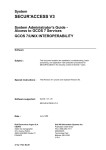
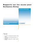
ARAA CODE –
PERMANENT ANCHORS
FOR ROPE ACCESS USE
Version #1e – 22/10/07
Refer regularly to ARAA web site to ensure that later versions or supplementary technical
papers have not rendered this version redundant
Australian Rope Access Association
C/o PH 03 5634 6296 Fax 03 5634 6234 Mobile 0419108128 [email protected] www.araa.net.au
PREFACE
This code of practice has been developed by the ARAA to clarify the requirements for permanently installed
anchor systems for rope access sites. Increasingly, buildings are having anchor systems designed and
installed by specialist companies, with the installed system provided for use by other companies to clean and
maintain the building or structure.
The ARAA has identified that in some cases, the installing companies require guidance from the Rope Access
industry to fully understand the needs of the users and building managers.
As a result, this document has been developed to aid the process.
Elements of this document may also be useful for installation of temporary anchor systems and also for
systems installed for general fall protection use.
It is recognised that this document is an initial version and that the industry is constantly striving to improve.
As a result, the reader is strongly encouraged to take note of the document version number and to regularly
check the ARAA web site for a/ updates of this version, and / or, b/ supplementary technical papers that may
be issued to cover specific topics. (ie. Technical paper on anchors drilled into concrete, aid anchors etc.)
Readers of this document should also obtain copies of Australian New Zealand Standards for rope access,
AS/NZS4488 parts 1 & 2 and the ARAA Industry Code and other relevant industry documentation (available
free from the ARAA web site – www.araa.net.au)
DISCLAIMER - This document has been developed as an aid to, and should only be used in conjunction
with, suitable operator training. Whilst every care has been taken in the preparation of this document,
users are advised to seek expert advice regarding specific projects - ARAA accepts no responsibility for
any error or omission resulting from use of this information. This document should be read in conjunction
with the ARAA Industry Code, with AS/NZS 4488 parts 1 & 2 and in conjunction with training provided to
rope access operatives. This document is one of a series to be placed on ARAA web site and users are
advised to check the site often as changes to these documents are expected – check that the latest
version is the one being used.
2
ARAA code - permanent anchors. This version Ver #1e 22/10/07
SCOPE
This document relates to PERMANENTLY installed anchors and anchor systems, intended for use by rope
access operatives working under the ARAA Industry Code. It is assumed that in many cases, the team that
installs the anchors may not be the same as those who actually USE the anchors and as such, clear
communication of the system’s capacity and limitations is extremely important. Temporary anchors are not
included in this document but elements of it may still be used as a guide to good practice.
1 INSTALLED SYSTEMS
A system permanently installed on a building or structure entails several unique steps that need to be carried
out before the system can be commissioned and handed over to the user and/or facility manager, ready for
use.
These unique steps are as follows:
Design incorporating:
o System layout
o Structural design (building/structure specific)
o Product design (relates to the actual anchor device)
Installation
Testing and certification
Provision of documentation
Each of these areas requires specific knowledge and skill, which a single installer may have, but in certain
cases, may also need to engage specialist assistance.
Each area is discussed in detail in the following text.
2 DESIGN
2.1
DESIGN - SYSTEM LAYOUT
The first step in designing the permanent anchor system is to layout the design. This is not necessarily a
structural function, but has more to do with the concept of the system and its suitability for task. This part
of the work is often carried out by an experienced operator who has a good understanding of issues of
use, installation and of relevant rescue requirements.
A Level 3 operator is often the most suitable person to undertake this step and often works in conjunction
with a Structural Engineer to achieve a safe and workable solution.
In laying out the design of any permanently installed anchorage system that is intended for regular use,
the designer(s) needs to address several factors including, but not restricted to the following list:
FACTOR
Access to and from the
anchor(s)
COMMENT
The system layout should strive to ensure there is always safe access to
and from the anchor point(s). In some cases this may mean the provision of
additional anchors or other access equipment (eg. Stairs, ladders,
guardrails) to allow access to the required location.
Operator competence
Designers should ensure that anchor systems are laid out in the simplest
practical manner so that wherever possible, the system is suitable for use
by Level 1 operators. Where this cannot be achieved, higher costs,
complications and hazards may result for the life of the building or structure.
Where a complex arrangement is necessary, special attention to marking
and user instructions need to be made.
Building managers and specifiers should take particular note of this when
reviewing design/installation offers to ensure a low offer is not going to
result in higher long term costs and complications.
Intended use
Many installations are specifically designed for access to one particular area
3
ARAA code - permanent anchors. This version Ver #1e 22/10/07
(eg. Roof access, façade access, façade access but windows only, etc).
Any person involved in laying out the installation needs to be mindful of the
importance to communicate and document the intended system use
Complexity
Any given system can be designed to be complex or simple. The decision
can have long-term consequences. A system may be simple and therefore
initially cheaper, but the on going costs of using and maintaining the system
can be very expensive for the life of the building. The decision between the
2 extremes (complex / simple) can also have a profound effect on the level
of supervision required for the works and may also affect other areas of on
going costs such as the required rescue method and any special equipment
that may be required as result of the layout.
Finally, the decision can have implications in the Hierarchy of Control. For
example, the layout of very simple and inexpensive anchor systems may be
tolerable on an existing building but would be seen as a very poor choice on
new works where the ARAA and the Regulatory Authority may see that the
solution adopted could have been carried out more competently but in fact,
was kept simple as an act of cost cutting – this leads to the crew being
potentially exposed to greater hazards for the life of the building. Eg, an aid
route consisting of individual anchors under a soffit may be the only
practical application on an existing building, but would be seen as a very
poor application on a new building where a, for example, continuous
monorail could have been built in. The rail spreads its load to a number of
mounting points and most importantly, eliminates virtually all need for the
operators to regularly connect and disconnect. In most cases also, the
monorail would allow for a much more rapid rescue to be carried out.
Practicality
In laying out the system, its practicality for use to undertake the tasks
required and for the persons using the system must be taken into account.
Laying out a poor system that leads to the users having difficulties or being
forced to undertake unnecessary and additional rigging is a poor outcome.
It will also not please clients to invest money in such installations only to find
that operators arrive on site and possibly, refuse to use the system without
modification.
Design loads
In laying out the initial plan of the anchor system, the loads created by the
system need to be considered, as often, the layout needs to be modified to
take account of the capacity of the structure to resolve the design loads. A
typical case is a timber-framed roof, where the loads can be extremely
difficult to resolve.
Rebelays/Reanchors,lateral
restraints, monorails
1/ Lateral restraint. The ARAA recommends that any building over 15
floors should have lateral restraints spaced at approximately 30m vertical
centres on the façade. Design loads for lateral restraints need to take
account of likely site loadings and the designer needs to be mindful of
issues of direct axial loadings. The ARAA recommends minimum design
loads of 2kN.
2/ Lateral restraints under overhangs. This is a situation where the
loadings may significantly increase due to the use of the anchor to pull the
operator in towards the façade. Lateral restraints too close (vertically) to the
overhang should be avoided and in many cases, it is simpler for the
operator to make use of a re-belay/re-anchor to achieve a similar result.
3/ Re-Belay/Re-anchor. These are used generally under overhangs so that
the operator can move to a new anchor point nearer the façade. Many
factors require consideration for these and the following list is a brief
overview:
Mounting method – desirable that anchor should not be loaded in
axial tension if drilled in.
Number of anchors provided at each point (ie. 1 or 2)
Spacing of anchors – maximum spacing should not exceed
operator’s easy reach.
4
ARAA code - permanent anchors. This version Ver #1e 22/10/07
operator’s easy reach.
Anticipated method of use including position of back up line
Anticipated method of rescue
Anticipated method of on-going inspection and testing
Issues relating to marking and labelling (anchors are often highly
visible to public)
For the above reasons plus specific site issues, ARAA recommends that
specialist advice should be sought when designing and installing these
anchors.
4/ Monorails. Due to the issues raised in 3/, it is often preferable to
consider, particularly on new works, the installation of a monorail in lieu of
re-anchors. The monorail if well designed, can simplify connection and
disconnection, ease many ergonomic issues and provide a simple rescue
path. In addition, the monorail may act as an excellent load spreader if a
number of fixing points to the structure are utilised.
Design out risks
Numerous site-specific hazards may arise which the system layout needs to
take account of. The designer(s) should strive to design out the hazards
and if not possible, to minimise their effect. The following is a non
exhaustive list of some:
1. RF hazards – working around aerials and dishes can cause both
hazards to the operators and issues to the supplier of the
communications equipment, with non-planned shuts and supply
interruptions.
2. Manual handling – the equipment to be used on site, which may
include heavy items such as davits, need to be able to be safely
handled and placed by the operator’s. Loads should be kept low,
able to be broken down into components and able to be tied off to
assist in placing safely.
3. Sharp edges – while operators need to be responsible for protection
of ropes over edges, the designer can play a large part in ensuring
building features make this easy or unnecessary or that specific
items are supplied to make protection possible.
4. Glass protection – quite apart from possible damage to facade
glass, many installations include glazed balustrades – these
generally cannot tolerate likely rope access loads and specific
hardware or design features are required to ensure operator and
structure safety.
5. Rope runs – on many installations, additional anchors are required
to allow rope runs to not need to pass over, under and through
complex areas and often, over sharp edges or near rotating
machinery – this is often evident on roof mounted ac plant.
6. Operator safety near edges – the design needs to ensure that the
operators can set up and use the system safely without resorting to
unreasonable measures – ie. A perimeter guardrail system or
parapet is far preferable to needing to run a fall protection system
and has less ability to be misused.
7. Falling items – safety of the public and the structure needs careful
thought – whilst rope access operators are trained to tie off all
personal gear, the need to handle loads adjacent to the building
edge, for example, simply makes dropped items more likely.
8. Water spray from AC units – many of these units can be a health
hazard to the operators – keeping rope runs and anchors away from
these where possible is good practice.
Rescue
Irrespective of the anchor system chosen, the ability to mount an effective
and rapid rescue MUST be taken into account at all stages of the
installation, beginning with the system layout. Whilst the site operators can
be expected to review and refine the rescue procedure, it is still a
requirement for the intended manner of rescue to be known and
documented from the point of design onwards.
In many cases, an excellent pre-rigged rescue capacity can be built into the
5
ARAA code - permanent anchors. This version Ver #1e 22/10/07
rope access system where, should a rescue become necessary, the rigging
is already set up to suit and a non-contact rescue can be rapidly carried out.
2.2
DESIGN – STRUCTURAL ASSESSMENT OF STRUCTURE & PRODUCT
DESIGN/MANUFACTURER
The preceding section dealt with the issue of design – system layout. This section deals with the next
components of the design – structural assessment of the building elements and the inter-related section of
design – product design / manufacture. The distinction between the 2 areas is important to highlight.
The design of products that are fixed to the structure or are used to fix anchors to the structure may involve
distinctly different skills to those required to actually design the load paths arising from the use of these
products into the structure. Further, in many cases, the products being fixed to the structure are often factory
built and the designer has total control over the product as it sits in the box, and may often offer guidance on
how to correctly install the product, but can have little input into how the loads are fed into and through the
structure.
The kinds of products that are likely to be covered by the above comments are:
Commercially available anchors
Fixings for use into concrete and masonry
Fixings for use into steel, timber and the like
Flashing materials
Roofing products
Grouts and other cementitious products
Industrial adhesives such as epoxy
Paints and other corrosion protection products
Persons choosing such products need to ensure they are fit for purpose, suitable for the anticipated loadings
and that they are used, installed, tested and maintained strictly in accordance with the manufacturer’s
specifications.
This still leaves the issue of structural design in relation to resolving the loads back into the structure.
2.2.1
IS AN ENGINEER REQUIRED?
The common question is whether an engineer is required for this sector of the work. The
following is copied directly from AS/NZS 4488.2 and sets the situation out fairly clearly:
The building or structure and anchorages shall be assessed by an engineer, unless it is clear
to a competent person that the anchorage system is structurally adequate. An example of
where an engineer may not be required is where an anchorage sling of the correct capacity is secured
around a solid permanent structure such as a plant room. However, if any doubt exists as to the
structural adequacy of the anchorage, an engineer shall make the assessment.
Dynamic loads under fall-arrest conditions can be considerably higher than the static
loads. If called upon to make the assessment t h e engineer shall certify in writing that all
combinations of loads in a wors t case situation can be safely contained by the proposed
structure and anchorage points.
From the above, the answer to whether an Engineer is required, is YES, unless the exclusions are
satisfied.
It should further be noted that the building owner / manager would demonstrate poor judgment not to insist on
adequate insurance for the works, including Professional Indemnity insurance – the use of a professional
engineer often assists to ensure this is provided.
6
ARAA code - permanent anchors. This version Ver #1e 22/10/07
Irrespective of who takes responsibility for the actual structural design component of the works, several issues
need to be considered. The following (non exhaustive) list sets out some typical points:
For product design – refer to AS 1170 and the manufacturer. ie. Not within scope of this doc.
Is the installation structurally adequate to deal with working and rescue loads
Corrosion considerations
Has the structure been adequately inspected/assessed to ensure that it has required capacity
Have issues that will be relevant been properly considered, such as:
i. Purlin thickness
ii. Purlin spacings
iii. Roof sheet thickness
iv. Roof sheet fixings
v. Condition of framing, particularly timber
vi. Condition of substrate and likely degradation over time
vii. Are the fixing methods suitable for the conditions (including consideration of
corrosion)
viii. Do the proposed installation crew have the knowledge and skills to install the works
correctly and as designed.
ix. Can the requirements and recommendations of the anchor and other item
manufacturers be followed
x. Are anchors and fixings going to be loaded in the direction intended by the designer.
This issue is particularly important with anchors that are drilled into concrete or
brickwork – the current position with Australian Standards and ARAA is that these
anchors may not be loaded in axial tension – see later notes.
Two final points are made in relation to anchor design:
1. As the anchors are generally rated for use by one person and as their “working loads” are generally far
lower than their “ultimate” load, the general view is that there is an expectation and acceptance that an
anchor may deform and possibly even locally damage the building, providing it does not fail, in the
event of a fall. As such, many deforming anchors are available on the market. The issue that MUST
be considered here however is how will any potential rescue be mounted. This may often mean more
anchors need to be installed or that a different form of anchor should be considered.
2. Following any fall or severe use, the anchor should be isolated out of service until fully assessed by an
Engineer or other competent person.
3 INSTALLATION
The next part of an overall permanent installation is the actual installing of the system. This involves following
the system layout and the structural design, and, using the products and methods specified, and carrying out
the works competently to ensure a safe outcome.
Numerous requirements exist in this area, including, but not limited to the following:
The persons installing the works are on a worksite them selves and will often have additional hazards
until the anchor system is installed. These hazards need to be controlled and the installation team
needs to be properly supervised.
The installation team needs to be competent to carry out the work in terms of;
o Working at height,
o Use of any access equipment being operated,
o Where appropriate, trained and assessed as competent to use products and equipment
involved in the installation – this may cover the actual anchor, the equipment being used to cut
or drill holes, adhesives, sealants, test equipment etc. In many cases, this may require
verification from the supplier or manufacturer, or a specific trade qualification
4 TESTING & RE-CERTIFICATION
2 types of test may be required:
1/ Proof load (used on a new or existing installation to demonstrate that the substrate is adequate)
2/ Verification test (in place of, or as well as, design check)
7
ARAA code - permanent anchors. This version Ver #1e 22/10/07
The proof load test is NOT used to test the anchor itself, but is used to provide confidence that the substrate is
or continues to be, adequate. This test is ONLY carried out on anchors drilled in to masonry materials (brick,
concrete) and it is generally specified in the user instructions for the system what level of testing is required
(ie. All each year or a percentage each year. It also may specify removal of some for inspection for corrosion)
Proof loads are generally carried out in axial tension.
The ARAA does not recommend proof-loading anchors fixed to non-masonry surfaces, unless this is
specifically required by the designer/installer.
A verification test is generally overviewed by an Engineer and carried out because of the difficulty of
calculating or inspecting for structural capacity or as an additional measure to “prove” adequacy. As such, it is
often carried out to the same loads as a proof load, but in some cases, the Engineer may specify higher loads.
At present, the proof load is 50% of the minimum anchor design load (ie. Rope access 6 or 7.5kN for
AS 1891 anchors)
Criteria – no visible permanent deflection/deformation
Note that in some cases, extra equipment may be required to ensure that the deformable part does
not deform (the test is intended to test the connection to substrate and the substrate – not testing
anchor itself).
The user instructions for the installation (see below) should define parameters for inspecting and
testing. If these are not available, the tester should contact the installation company for guidance
before proceeding.
Verification tests are often carried out in shear or specific directions as defined by the designer (refer to project
documentation)
The current anchor inspection requirements set out in AS/NZS 4488.2 (clause 7.1.3) are as follows:
Inspection interval shall be 12 months max.
Visually inspect in addition to any requirements set out by manufacturer.
Inspect parent structure for signs of deterioration that may affect anchor strength.
Any DRILLED-IN (masonry/concrete) anchors should be proof tested in accordance with 3.1.2(g)
5
DOCUMENTATION
Once the installation is physically complete, and any testing required has been undertaken, the final stage of
the installation is to provide the correct documentation for the system. Depending upon the project, its
specific details and products used, there will be a range of issues to be covered. The following is a list of the
common requirements and should be regarded as a minimum upon which other information may be added:
Rigging plan – this is a must – the user must be shown how the designer(s) intended the system to be
used for all “drops” or use locations.
Engineer(s) reports, where relevant
Manufacturer’s instructions (specific items)
Maintenance requirements
Name and contact details of designing / installing company(s)
Contract number when relevant to allow tracing of project
Date of installation
Any additional training requirements (specific to the installation)
Supervision level required to use the as-designed installation
User instructions
A listing of any special components required (slings, protection etc)
SWMS for the as-designed system
Assumed method of rescue – so the site team can review this and decide to follow or use another
method
A more complete listing of documentation and marking requirements is provided in the appendix.
8
ARAA code - permanent anchors. This version Ver #1e 22/10/07
APPENDIX
Appendix A
Appendix B
Appendix C
Appendix D
Appendix E
Appendix F
Appendix G
Appendix H
Design and installation phases of typical rope access
permanent anchor installation
Anchors – documentation and marking
Anchor types
Anchors into masonry and concrete
Anchors fixed to roof sheeting only
Deforming anchors
Anchor connection points – 1 point or 2?
Hints for designers
9
ARAA code - permanent anchors. This version Ver #1e 22/10/07
APPENDIX A
Chart illustrating various phases of design and installation of a permanent
anchor system for rope access
10
ARAA code - permanent anchors. This version Ver #1e 22/10/07
APPENDIX B
ANCHORS – DOCUMENTATION AND MARKING
ROPE ACCESS
PERMANENT ANCHOR SYSTEMS
DOCUMENTATION AND MARKING REQUIREMENTS
Any permanent rope access anchor system, (intended to be left in place for permanent use)
following installation, should be supplied with documentation that is kept on site by building
management and should be made available to any rope access crew prior to works proceeding.
This documentation should include at least the following information:
Installing person/company, date of installation and full written instructions to enable anchor
system to be understood by a competent rope access operator
An initial risk assessment
Any details required to indicate servicing and maintenance requirements for the installation
Testing information, if any, relevant to the installation
Contact details to the installing person/company and any additional Engineering body
Plan of area of anchors (generally a roof plan) and to include rigging plan for all
drops/anchors
Location of all anchor points with marking to show intended use (ie. Main anchor, diversion
etc) and intended direction of loading
A statement setting out the purpose of the designer in choosing anchor locations – ie. Are
they for general façade access, window cleaning only, gutter cleaning etc.
Definition of whether anchor is within the zone of 2m from an edge or potential fall zone
Where anchors are placed on façade or vertical surface of structure for purposes of reanchor (re-belay), diversion, deviation or lateral stability, an elevation should be shown for
each face with location and purpose of each anchor shown.
Where the users are required to supply/use additional equipment such as slings, the details
of this requirement should be set out to clearly define what length, rating, configuration etc is
required. Additionally, if such rigging requires the use of a Rigging qualification, this should
be noted.
Requirements for public protection in conjunction with the works – in some cases this may
require drawings and on occasions, special equipment, permits etc.
Requirements for any special protection needing to be placed or supplied by the operatives,
to protect the building, the equipment and the operators.
Details of any special requirements that are unusual for a competent rope access crew
Anticipated rescue plan and any special details, equipment or skills that are expected of the
crew in relation to this plan
The minimum Supervisor level required for the works and where relevant, the minimum team
size required to carry out anticipated works (note, works may later arise that utilise the
anchor system in a manner that differs from that specified in the user manual – in such
cases, it is the responsibility of the Supervisor to document these differences and to assess
the system’s capacity to deal with these new circumstances)
All permanent anchor points should be marked with the following information. This should, where
practical, be fixed to or at, each anchor but may, in some cases be fitted at one location such as the
access door to a roof. A case where it is understood that individual anchors may not be able to be
individually marked, is those on a façade where they may cause aesthetic issues. Irrespective of
this, all anchors should be marked with at least a serial No or batch No to enable traceability of
individual anchors.
11
ARAA code - permanent anchors. This version Ver #1e 22/10/07
Subject to the above comments, marking should include:
Manufacturer’s contact
Installer’s contact
Load rating and direction.
Specific use if not also suited as a fall protection anchor (min. 15 kN ult)
Most recent inspection/service date
Following any incident such as a fall, affected anchors should be tagged and withdrawn from service
until engineering assessment/inspection has been carried out by a competent person and the
anchor replaced/repaired or re-certified.
The documentation supplied for use on site by the installation person/company should be signed by
an individual of that body as the person taking responsibility for the proper design, specification and
installation of the works.
12
ARAA code - permanent anchors. This version Ver #1e 22/10/07
APPENDIX C
ANCHOR TYPES
A
Primary anchor
B
Counterweighted anchor (sometimes called a “needle”)
C
Diversion
D
Re-anchor (re-belay)
E
Deviation
F
Lateral restraint
G
Improvised (using slings) (in the cases above, use of a steel column and a lift motor
room has been made but sometimes other devices are used such as rocks, trees,
vehicles, machines etc)
H
Aid route
I
Edge protection
J
Dead weight anchor
K
Davit (primary anchor)
Anchor design loads.
AS/NZS 4488.2 requires the minimum design load of 12 kN ult for any primary anchor. However as AS/NZS
1891.4 (fall protection) uses anchors of 15 kN ult, we strongly suggest all anchors installed be designed for 15
kN ult to ensure suitability for use in both conditions. Any anchor designed for 12 kN ult only, MUST be
marked to ensure that users are warned of its limitations.
13
ARAA code - permanent anchors. This version Ver #1e 22/10/07
The following excerpt from AS/NZS 4488.2, clause 5.3 details this:
(iv)
Where the anchorage point is not capable of sustaining an ultimate load of
15 kN in the direction of loading as a fall-arr est anchor, it shall
permanently labeled as follows:
be
For industrial rope access only. Ultimate strength less than 15 kN . Ch eck with
(building, st ructu re, and the like) owner before use.
Absence of a label as specified above should not be grounds for assumption by
any user of the anchorage that it is capable of sustaining a 15 kN load, without
first checking w ith the owner of the structure.
NOTE: The specified minimum load on an anchorage for rope suspension
purposes is 12 kN. This is derived as the maximum design tensile force
developed in an energy absorber, multiplied by a safety factor of 2. This minimum
load does not apply to slings (see Item (b)) .
Design loads of other anchors are specified as follows:
ANCHOR STRENGTH
Anchor type
Diversion anchor
Min ult
strength
15 kN
12 kN
12 kN
12 kN
Deviation anchor
6 kN
Aid anchor
Lateral restraint
12 kN
2 kN
Fall protection anchor
Primary anchor
Re-anchor (re-belay)
Comments
Design for 15 kN where possible
Effectively a new main anchor
Unless it can be proven lower load x FOS 2 is
acceptable – see AS/NZS 4488.2
Based upon a 20 degree max. deviation – higher
angles may need greater load capacities – this
requires engineering over view
Min load – consider action of anchor as used, to
define actual load
For further information on the use of counterweighted anchors refer to the ARAA web site for a specific
guidance note.
For information on dead weight anchors, refer to EN Stds – they are used very little in Australia / New Zealand
and as such, little work has been carried out on guidance material at this time.
14
ARAA code - permanent anchors. This version Ver #1e 22/10/07
APPENDIX D
ANCHORS INTO MASONRY AND CONCRETE
We refer to anchors that have been installed into existing masonry (brickwork/block work) and concrete as
“drilled in”.
Many excellent products exist for use in these location including epoxy based and mechanical style anchors,
some of which have undercutting features to ensure a satisfactory grip to the substrate.
The ARAA takes a conservative view with the use of these anchors, in line with many Standards Committees
and other industry associations – for the present our position is that no drilled in anchor may be loaded in axial
tension (pull out).
The Australian/New Zealand Standard for rope access AS/NZS 4488.2 contains the following text:
(viii) Where used, drilled-in, friction and glued-in anchorages shall be
placed so that the shear load is at least twice the tension load.
For collared eye-bolts this translates to a pull at an angle
exceeding 20 degrees to the surface in which the bolt is installed.
not
This allows for an element of axial tension in the anchor but must be associated with the largest component of
load being in shear.
The reason behind this conservative approach is simple – no matter how good the manufactured fixing
product is, the chance of improper fitting on site plus the possibility of substrate damage over time, leads us to
take a very conservative view.
This view is under review and MAY change in the future, particularly if we can establish a system where
installers can be assessed as competent to install certain products.
In many cases, it is possible / practical to through bolt (with a suitable backing plate) and this is generally the
preferred form of connection. On new works with concrete, cast in fixings or embedded PVC tubes (to allow
later through bolts) are often a practical approach.
A specific area where this conservative approach is often a problem is re-belay/re-anchors under soffits. On
new works, there should be no reason to prevent casts ins or through bolts being used (see earlier notes re
preference for monorail to re-anchors) however on existing works, sometimes an anchor in axial tension is
almost unavoidable.
In such cases, the involvement of very experienced designers and operators may be required to devise a
system that will still be safe to operate. It is anticipated that such situations would be quite rare.
Check the ARAA web site regularly for updates on this position.
It should be noted also, that the use of drilled in anchors requires testing both at installation and every year
thereafter. The following excerpt from AS/NZS 1891.4 details this:
(ii)
In addition to the assessment made in Item
(i), drilled-in, glued-in and friction anchorages
(See Item (viii)) shall be proof loaded by application of
an axial pullout force of 6 kN after installation a n d as
part of subsequent periodic inspections (see Clause
7.1.3). Records of such proof loading shall be kept
with the b u il d in g
owner or manager
for
reference by s u b s e q u e n t users of the anchor
system.
15
ARAA code - permanent anchors. This version Ver #1e 22/10/07
APPENDIX E
ANCHORS FIXED TO ROOF SHEETING ONLY
Increasingly, anchors are being supplied that are fixed to roof sheeting only without any additional connection
to the structure below.
Numerous methods of fixing are used, the most common being high strength rivets.
The ARAA has no particular problem with this form of anchor providing it is designed and installed correctly
and is suited for the purpose intended. Several questions should be asked of designers / installers before
using this form of anchor for rope access purposes:
1. Is it suitable for a sustained load in lieu of an instantaneous fall load?
2. Is it rated and has it been tested for use with the type of roof sheeting and roof sheeting fixing? (Many
of these anchors are designed for use with overseas roofing systems, which can differ in detail)
3. Is a second anchor required to ensure that there are 2 points of connection?
4. Is there a strategy in place to deal with any rescue that may become required?
5. Is there a minimum area of roof sheeting required to ensure that the sheet to roof framing is adequate
for the loads likely to be imposed?
6. Is the unit suitable for use with loads applied longitudinally as well as laterally on the sheet? If not, will
directional loads on site cause problems?
7. Is the connection point(s) suitable for rope access and for the directions of loading likely to be imposed
on site?
8. Is there adequate signage and user instructions?
9. Is there safe access to and from the system?
This is another area that the ARAA intends to investigate further in the future – readers are advised to check
the ARAA web site for updates.
16
ARAA code - permanent anchors. This version Ver #1e 22/10/07
APPENDIX F
DEFORMING ANCHORS
Like roof sheet mounted anchors, there is an increasing use of deforming fall arrest anchors for rope access
use.
Again, the ARAA has no particular issue with the use of this style of anchor providing the basic requirements
are met.
Most of the requirements are similar to roof sheet mounted anchors and are repeated here along with some
specific requirements:
1. Is it suitable for a sustained load in lieu of an instantaneous fall load?
2. Is a second anchor required to ensure that there are 2 points of connection? (if there are 2 points, is
one specifically for work and the other for arresting any potential fall?)
3. Is there a strategy in place to deal with any rescue that may become required? (if the anchor is
deformed, can it be used for a rescue?)
4. Is the unit suitable for use with loads applied longitudinally as well as laterally? If not, will directional
loads on site cause problems?
5. If the anchor is a deforming type, will it sustain likely working loads (as distinct fall loads) without
permanent deformation?
6. Whilst the anchor itself may have been thoroughly bench tested, has the application ON SITE, been
verified as suitable for likely loads of use and / or a fall?
7. Is there adequate signage and user instructions?
8. Is there safe access to and from the system?
17
ARAA code - permanent anchors. This version Ver #1e 22/10/07
APPENDIX G
ANCHOR CONNECTION POINTS – 1 POINT or 2?
Rope access operators are trained to “play it safe” and to connect independently at all times.
However in the case of an anchorage, at some stage, it all becomes 1 when the load gets back to the
structure.
It is recognised that for ease of use, for cost and for aesthetics, it is often preferable to have one anchor to
which the operator’s 2 ropes can connect (ie. 1 operator x 2 ropes).
If the anchor is an engineered device, designed and verified for purpose, the ARAA sees no objection to
connecting both the operator’s ropes to this single anchor. The following comments are suggested as good
practice:
1. In line with trying to ensure that all permanent anchors are suitable for ease of use by Level 1
operators, it is strongly suggested that there should be 2 separate connection points – one for each
rope.
2. The overall anchor design load shall be a minimum of 12 kN ult but should preferably be 15 kN as a
minimum. (it is recognised that the anchor need not meet 2 x 12 kN capacity as would be required
with use of 2 separate anchors)
3. The anchor needs to be designed and installed with a strategy for any potential rescue in place.
4. The markings and user instructions need to clearly define the capacity of the anchor (necessary to
ensure no connection of a second person unless rated as such)
5. The anchor needs to take into account likely directions of site loading from operator’s ropes and
hardware.
18
ARAA code - permanent anchors. This version Ver #1e 22/10/07
APPENDIX H
HINTS FOR DESIGNERS
CONNECTION POINTS
Keep work rope and backup rope connection points close together unless there is a reason for them to
need to be apart
Keep connection points without sharp edges, by using rounded material, chamfered holes etc.
Set up connection points for use by karabiner or shackle – preferably do not rely on operator tying into to
point
Ensure connection point will not be loaded in a way that weakens it – sometimes this may require a
moveable head or design modification to achieve
LAYOUT
Provide more anchors and less or no diversions to keep layout simple and less chance of mistake
Design systems to be as simple and straightforward as possible and wherever possible, suitable for
Level 1 operators – less chance of mistake and generally more economic in the long run
Keep rope runs away from rotating parts, areas that are difficult to rig or feed ropes through, and away
from sharp edges
On building edges, consider installation of edge detail that will not damage rope and/or supply portable
devices for rope protection (ensure they cannot drop!)
Where glass balustrades are used, ensure rope is kept away from glass – often achieved by use of davit
or steel framing with specific rope path
Can all members of the team reach all required anchors safely?
Has long-term maintenance of the anchor system been adequately considered?
Will the system allow access to ALL the points likely to be required by the client? This may include areas
of roof, parts of façade, other structural elements on areas such as chimneys, cooling towers, cranes etc.
Does the system also need to allow for powered access for heavy-duty works? (ie. Re glazing, painting
etc) Anchors are often installed capable of being used for both purposes.
RE-ANCHORS (RE-BELAY)
Avoid these where possible, particularly on retrofits as it may be difficult to prevent anchors needing to be
drilled in and used in axial tension
Use monorails in preference to individual anchors – monorails should be regularly fixed to substrate so
that a failure of an individual fixing point will not render entire rail unsafe.
Monorails should be designed to allow multiple operators and/or rescue capability
PUBLIC PROTECTION
The layout of the system needs to consider how public protection will be achieved. The planned manner
needs to be communicated to the users clearly.
At times, permanent elements may need to be supplied or installed to assist with public protection.
MANUAL HANDLING
A rope access site is a work place – the designer must ensure that any hardware intended for use on site
by the crew can be safely handled and placed without undue strain and danger. This is likely to affect
davits, counterweights, “needles” and the like.
Heavy or bulky items are often built in broken down form to allow safe and simple carriage and
placement.
RESCUE
Ensure that rescue is considered at design layout stage and the intended method communicated clearly
to users (in writing)
Ensure that a landing point (if rescue is intended DOWN) is in an area where emergency crew can reach
(this can be a problem on apartment blocks where the landing may be in someone’s private space)
INSTRUCTIONS
The ARAA suggests that the user instructions should be reviewed by a competent rope access operator
unfamiliar with the job to verify the instructions are adequate to inform how to go about the works in the correct
manner. This particularly applies to issues such as (non exhaustive list):
Correct use of anchors for any given drop
Public protection
19
ARAA code - permanent anchors. This version Ver #1e 22/10/07
Rescue method
Protection of equipment
Protection of building or structure
Level of supervisor required for team
Size of rope access team required
20
ARAA code - permanent anchors. This version Ver #1e 22/10/07