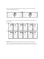
1
A” pair of connections on the Dual Maximizer, and connect (short-circuit) the “Input B”
pair of connectors.
Dual Maximizers can be installed in the same system, and on the same string, as single
Module Maximizers. Since the core technology is identical, these products can be used in
the same power system, and can communicate via the same Gateway/Maximizer Management
Unit communications system.
Mechanical Schematic of the Tigo Energy Dual
Maximizer
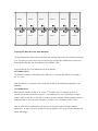
The Dual Maximizer has six cables. The long cables on the ends are the cables for the string,
which connect one Maximizer to the next.
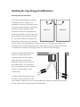
There are two pairs of PV input cables for the Dual Maximizer,
known as “Input Circuit A” and “Input Circuit B”. Circuit A is the
left pair when the Maximizer is clipped into the frame of the
module. The PV input cables are at different lengths, to help
differentiate them and prevent mis-wiring in the field. The Input
A wires are shorter, and the Input B wires are longer.
Input A:
0.2m, 8 in.
Input B:
0.3m, 12 in.
When two PV modules are connected to the Tigo Energy Dual
Maximizer, they are each kept at their optimal power point, and
data is provided for each one (as would be the case if they were
each connected to a single Module Maximizer). Electrically, they
are combined in series for the output cable from the Dual
Maximizer.
The Dual Maximizer comes attached to the same mounting
bracket as the Module Maximizer, and is designed to be
mounted in the top right corner of a PV module frame. The setscrew in the corner of the bracket can provide tension, and
allows for electrical bonding to the frame.
Series cables:
1.3m, 4 ft.