1
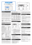
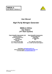
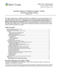
MSQ18LA
Nitrogen Generator
for Mass Spectrometers
User Manual
Document No. 065779
November 2008
MSQ18LA User Manual __________________________________________________________________
©2008 by Dionex Corporation
All rights reserved worldwide.
Printed in the United States of America.
This publication is protected by federal copyright law. No part of this publication may be copied or
distributed, transmitted, transcribed, stored in a retrieval system, or transmitted into any human or computer
language, in any form or by any means, electronic, mechanical, magnetic, manual, or otherwise, or
disclosed to third parties without the express written permission of Dionex Corporation, 1228 Titan Way,
Sunnyvale, California 94088-3603 U.S.A.
The MSQ18LA Nitrogen Generator is manufactured for Dionex by:
Peak Scientific Instruments
Fountain Crescent
Inchinnan Business Park
Inchinnan, Renfrewshire
PA4 9RE
Scotland, UK
DISCLAIMER OF WARRANTY AND LIMITED WARRANTY
THIS PUBLICATION IS PROVIDED “AS IS” WITHOUT WARRANTY OF ANY KIND. DIONEX
CORPORATION DOES NOT WARRANT, GUARANTEE, OR MAKE ANY EXPRESS OR
IMPLIED REPRESENTATIONS REGARDING THE USE, OR THE RESULTS OF THE USE, OF
THIS PUBLICATION IN TERMS OF CORRECTNESS, ACCURACY, RELIABILITY,
CURRENTNESS, OR OTHERWISE. FURTHER, DIONEX CORPORATION RESERVES THE
RIGHT TO REVISE THIS PUBLICATION AND TO MAKE CHANGES FROM TIME TO TIME
IN THE CONTENT HEREINOF WITHOUT OBLIGATION OF DIONEX CORPORATION TO
NOTIFY ANY PERSON OR ORGANIZATION OF SUCH REVISION OR CHANGES.
TRADEMARKS
Teflon is a registered trademark of E.I. du Pont de Nemours and Company.
PRINTING HISTORY
Revision 01, November 2008
Page 2 of 18
MSQ18LA User Manual __________________________________________________________________
Contents
Contents............................................................................................................................. 3
Safety Notice..................................................................................................................... 4
Technical Specifications.................................................................................................. 5
Introduction........................................................................................................................ 6
Unpacking and Installation.............................................................................................. 7
Useful Installation Information................................................................................ 8
Electrical Connection ............................................................................................... 8
Generator Environment ........................................................................................... 9
Connections to Rear of Unit ................................................................................. 10
Operation ......................................................................................................................... 11
Pressure & Flow Adjustment ................................................................................ 11
Unusual Operation ................................................................................................. 11
System Drain........................................................................................................... 11
Service ..................................................................................................................... 11
Alarm System.................................................................................................................. 12
High flow - Alarm stage 1...................................................................................... 12
High flow - Alarm stage 2...................................................................................... 12
High flow - Alarm stage 3...................................................................................... 12
Service - Indication stage 1 .................................................................................. 12
Service - Indication stage 2 .................................................................................. 12
Service - Indication stage 3 .................................................................................. 12
Notes on Alarms ..................................................................................................... 13
Routine Maintenance..................................................................................................... 14
Maintenance Schedule.......................................................................................... 14
MSQ18LA Pneumatic Diagram............................................................................ 15
MSQ18LA Wiring Diagram ................................................................................... 16
MSQ18LA Maintenance Log ................................................................................ 17
Page 3 of 18
MSQ18LA User Manual __________________________________________________________________
Safety Notice
These instructions must be read thoroughly and understood before installation and operation of
your MSQ18LA Nitrogen Generator. Use of the generator in a manner not specified MAY impair
the SAFETY provided by the equipment.
When handling, operating, or carrying out any maintenance, personnel must employ safe
engineering practices and observe all relevant local health and safety requirements and
regulations. The attention of UK users is drawn to the Health and Safety at Work Act 1974, and
the Institute of Electrical Engineers regulations.
Page 4 of 18
MSQ18LA User Manual __________________________________________________________________
Technical Specifications
Generator Environment
Minimum operating ambient temperature
5°C (41°F)
Maximum operating ambient temperature
25°C (77°F)
Maximum relative humidity
70%
Maximum altitude
2000 meters
Nitrogen Outlet
Maximum flow
18 l/min (0.64 cfm)
Maximum pressure
6.9 bar (100 psi)
Particles
< 0.01 um
Outlet 1/4" BSP
1
Pressure gauges
1
Phthalates
None
Suspended liquids
None
Startup time
30 min
Electrical Requirements
@230 V ± 10% (50/60 Hz)
3.6 A
FUSE DETAILS
Current rating
10.0 A
Voltage rating
250 V
Breaking capacity @250 V
1500 A
Type
UL/CSA, T10 A/250 V
Electrical connection
C19; Single-phase power cord
Noise level
54 dBA @ 1 m
General
Dimensions in cm (inches) W x D x H
40 x 70 x 71
(15.7 x 27.5 x 28)
Weight
Shipping weight
60 kg (132 lb)
85 kg (187 lb)
Page 5 of 18
MSQ18LA User Manual __________________________________________________________________
Introduction
Welcome to the user manual for the MSQ18LA Nitrogen Generator. Enclosed in this manual you
will find the information required to ensure that your generator is operated and serviced according
to our recommended guidelines, which will prepare you for long and trouble-free nitrogen
generation.
Please review each of the following sections carefully and ensure that the maintenance log at the
rear of this manual is updated for future reference.
Thank you for selecting Dionex to meet your gas generation needs. Should you require any
further assistance or support, please do not hesitate to contact your local Dionex Service
Representative.
Page 6 of 18
MSQ18LA User Manual __________________________________________________________________
Unpacking and Installation
Although every precaution is taken to ensure safe transit and packaging, it is advisable to fully
inspect the unit for any sign of transit damage.
Check the “SHOCKWATCH” label for signs of rough handling prior to unpacking:
ANY DAMAGE SHOULD BE REPORTED IMMEDIATELY TO THE CARRIER AND DIONEX.
Follow the unpacking instructions posted on the side of the crate. It will require two people to lift
the crate clear and to maneuver the generator onto the floor.
Removal of Transit Bracket
Remove the side cover from the cabinet.
Remove the two screws, the hex bolt, and the
Transit Bracket which secures the compressor
to the cabinet.
Make sure the compressor mounts are located
on their positioning bosses.
Refit the side cover to the cabinet.
Important Note: The Transit Bracket must be removed prior to switching
the unit on. Failure to do so will result in LOUD NOISE and will cause
damage to the equipment.
The unit can now be moved to its final location on the castors provided.
Note: Included with the generator is a plastic envelope pack containing manuals and fittings. Be
careful not to discard these with the packing. The MSQ18LA User Manual (P/N 065779) is on the
MSQ Manuals CD (P/N 062793), which is part of the MSQ Ship Kit (P/N 062792). The MSQ Ship
Kit is a no-charge item that ships with every new MSQ order.
Please save the product packaging and Transit Bracket for storage or future shipment of
the generator.
Page 7 of 18
MSQ18LA User Manual __________________________________________________________________
Useful Installation Information
The diameter of the tubing which will be connected to the air outlet is important and is determined
by the length of tubing required. Failure to follow these recommendations could lead to
accelerated compressor wear.
•
•
10 meters. Use 6/4 (6mm O/D, 4mm I/D) Teflon® PTFE (polytetrafluoroethylene) tubing.
10 - 40 meters. Use 10/8 (10mm O/D, 8mm I/D).
A combination of 6/4 and 10/8 tubing (see imperial units below) may be used to ensure that there
is no large diameter tubing within the lab (i.e., use 6/4 tubing for the first 10 meters and 10/8
tubing for the final 20 meters).
The imperial equivalents are:
• 6/4 = 1/4” OD, 3/16” ID
• 10/8 = 3/8” OD, 5/16” ID
Keep connections and bends to a minimum.
The generator is supplied with 6mm Push-in Legris fittings and 2M of PTFE tubing (included with
every new MSQ).
Electrical Connection
Important Electrical Notice
This unit is classified as SAFETY CLASS 1 equipment. THIS UNIT MUST BE GROUNDED.
Before connecting the unit to the wall outlet supply, please check the output voltage. The
electrical requirement is 230 V (50/60 Hz), 3.6 A.
EARTH/GROUND (E): Green & Yellow
LIVE (L):
Brown
Neutral (N):
Blue
or
or
or
Green
Black
White
Connect the generator to a single-phase supply, using the power cord provided.
Page 8 of 18
MSQ18LA User Manual __________________________________________________________________
Generator Environment
The generator is designed for indoor use only. It should be installed adjacent to the mass
spectrometer it is supplying. If this is not convenient then the unit can be located elsewhere;
however, consideration should be made of the lengths of pipe runs as pressure drops can result
from extended runs of pipe. Please see “Useful Installation Information” (page 8) for further
details.
Performance of the generator (like all sophisticated equipment) is affected by ambient conditions.
Care should also be taken to the proximity of air conditioning outlets. These can sometimes give
rise to “pockets” of air with high relative humidity. Operation of the unit within such a pocket could
adversely affect its performance. Consideration should also be given to the air flow around the
unit. It is recommended that an air gap of 75mm (3”) should be maintained down both sides, at
the rear, and across the top of the unit. Please refer to the drawing below for the general
dimensions of the unit.
Maximum Ambient Conditions: 25°C (dry bulb) 70%RH (Max)
General Dimensions
Unit must always be placed on a level surface. Failure to do so will affect the performance
of the generator.
Page 9 of 18
MSQ18LA User Manual __________________________________________________________________
Connections to Rear of Unit
Serial Plate
Input Power
(230 V ONLY)
Fuse
Gas Output:
1/4” BSPP female
Water Outlet:
1/4” BSPP female
Unit Controls
PLC Display
Output Regulator
On/Off
Switch
Alarm
Light
Service
Light
Pressure
Gauge
Internal Pressure
Gauge
Page 10 of 18
MSQ18LA User Manual __________________________________________________________________
Operation
The MSQ18LA Nitrogen Generator is designed specifically to minimize operator involvement.
Given that the system is installed as described in earlier sections and is serviced in accordance
with the maintenance recommendations, then it should simply be a matter of turning the
generator on. The generator will automatically produce the factory default flow and pressure.
Pressure & Flow Adjustment
The system is configured in the factory to give standard Outlet Pressure and Flow Rate (see
“Technical Specifications” on page 5). These settings should NEVER require adjustment
during normal operation. During service/fault diagnosis, the settings can be changed by
adjusting the pressure regulator and flow controller situated on the side panel (see page 10).
Please contact your local Dionex Service Representative for further instructions.
Unusual Operation
If at any time the generator begins to emit excessive noise or vibration, then it should be switched
off and you should contact your local Dionex Service Representative as soon as possible.
System Drain
Please ensure that the drain port at the rear of the compressor is led to a suitable connection or
container. It should be noted that the generator will expel considerable amounts of water from this
port. If a container is used, it should be emptied at regular intervals.
NOTE: The container must not have an airtight seal.
Service
Ensure that the generator is serviced in accordance with the maintenance recommendations (for
details, refer to “Maintenance Schedule” on page 14).
Page 11 of 18
MSQ18LA User Manual __________________________________________________________________
Alarm System
High flow - Alarm stage 1
The red ALARM LED flashes and the buzzer sounds for 1 second every 30 seconds.
This is triggered after 8 hours of continuous running of high flow.
The alarm system resets automatically after the MSQ18LA returns to compressor cycling.
High flow - Alarm stage 2
The red ALARM LED flashes and the buzzer sounds for 1 second every 10 seconds.
This is triggered after 12 hours of continuous running of high flow.
The alarm system resets automatically after the MSQ18LA returns to compressor cycling.
High flow - Alarm stage 3
The red ALARM LED flashes and the buzzer sounds constantly.
This is triggered after 18 hours of continuous running of high flow.
The alarm system can only be reset after intervention of a Dionex Service Representative.
Service - Indication stage 1
The yellow SERVICE LED flashes and the buzzer sounds for 1 second every 60 seconds.
This is triggered after 3000 hours of compressor duty since the last service.
The service alarm system can only be reset after intervention by a Dionex Service
Representative. From this point you have an additional 1000 hours of compressor duty, at which
time the control system will force the compressor to stop. It is, however, unlikely that the
compressor will last this long and you should arrange for a service visit as soon as possible.
Service - Indication stage 2
The yellow SERVICE LED flashes and the buzzer sounds constantly.
This is triggered after 3900 hours of compressor duty since the last service. This is your warning
that in another 100 hours the compressor will stop.
Service - Indication stage 3
The yellow SERVICE LED flashes and the buzzer sounds constantly.
This is triggered after 4000 hours of compressor duty since the last service. The control system
will force the compressor to stop.
Page 12 of 18
MSQ18LA User Manual __________________________________________________________________
Notes on Alarms
The compressor cycle time is dictated by the flow requirement of the unit and is not driven by the
PLC (Programmable Logic Controller). As the flow requirement reduces, the internal pressure
switches will start the compressor cycling. The PLC will detect if the compressor starts cycling
and, if so, will reset the alarm condition. Hence, if there is a high flow requirement, the
compressor will not cycle and the alarm stages will progress.
If the alarm sounds at stage 1 or stage 2 during a low flow output, arrange for technical
assistance.
If a leak in the system develops, the compressor will keep running continuously and not cycle.
After a period of 18 hours, the unit would go into stage 3 of the alarm. Arrange for technical
assistance to reset the alarm and find/fix the problem.
Page 13 of 18
MSQ18LA User Manual __________________________________________________________________
Routine Maintenance
Servicing and/or repair of the generator should only be undertaken by a TECHNICALLY
COMPETENT PERSON, with the generator in its safely isolated condition.
SAFELY ISOLATED CONDITION
Definition: The unit is in a Safely Isolated Condition when it is disconnected from its application,
fully de-pressurized, and isolated from the electrical supply. Directions for isolating the generator
are shown below.
ISOLATING THE GENERATOR
a) Switch off the unit.
b) Unplug the unit from the main power supply and remove the power cord from the rear of
the unit.
c) Disconnect from the application.
d) Ensure the internal pressure gauge (page 10) reads zero prior to carrying out any work.
Maintenance Schedule
SERVICE INTERVAL
COMPONENT
PEAK
PART NO.
6 MONTHS
COALESCING FILTER
02-4335
COMPRESSOR INLET FILTER
02-4640
1 YEAR
DIONEX KIT
PART NO.
068349
RAC FILTER
00-4425
The Lesser of
Every 3000 Hours
or 18 Months
COMPRESSOR ASSEMBLY
08-8069
069347
ALTERNATIVE TO
COMPRESSOR ASSY.
COMPRESSOR RE-FIT *
06-5529
No Dionex
P/N
* Compressors can be re-fitted (as an alternative to replacement) up to 3 times. This is a more
cost-effective solution, but a degree of technical expertise is required and it can be timeconsuming.
Compressor
Assembly
RAC Filter
Inlet Filter
Coalescing Filter
Page 14 of 18
MSQ18LA User Manual __________________________________________________________________
MSQ18LA Pneumatic Diagram
Page 15 of 18
MSQ18LA User Manual __________________________________________________________________
MSQ18LA Wiring Diagram
Page 16 of 18
MSQ18LA User Manual __________________________________________________________________
MSQ18LA Maintenance Log
Serial Number _____________
Work Done
Remarks
Page 17 of 18
Name
Date
MSQ18LA User Manual __________________________________________________________________
Page 18 of 18