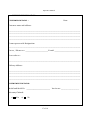
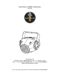
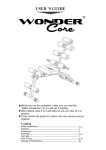
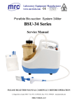
1
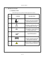
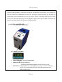
Operation Manual for
HIGH TEMPERATURE CALIBRATOR
CALI-1200HN
PLEASE READ THIS MANUAL CAREFULLY BEFORE OPERATION
3, Hagavish st. Israel 58817 Tel: 972 3 5595252, Fax: 972 3 5594529 [email protected]
MRC.VER.01-5.12
Operation Manual
INDEX
S.NO
1
CONTENTS
PAGE NO
BEFORE YOU START
4
1.1 SYMBOLS USED
4
1.2 SAFETY INFORMATION
5-7
8
2
INTRODUCTION
8
TECHNICAL SPECIFICATIONS &
ENVIRONMENTAL CONDITIONS
3.1 TECHNICAL SPECIFICATIONS
8-10
3
3.2 ENVIRONMENTAL CONDITIONS
3.3 WARRANTY
10
10-11
11
QUICK START
4.1 UNPACKING
11
4
4.2 SET-UP
11-12
2 of 18
Operation Manual
S NO
5
CONTENTS
PARTS & CONTROLS
5.1 GENERAL ASSEMBLY
PAGE NO
12
12
12
5.2 DISPLAY
13
5.3 HEATER BLOCK
6
13
OPERATING PROCEDURE
13
6.1 OPERATIONAL PROCEDURE
14
6.2 TO SELECT THE UNIT ˚C OR ˚F
14
6.3 SWITCH TEST
14
6.4 FORCED AIR COOLING
7
14-15
STORING & TRANSPORTING THE CALIBRATOR
8
MAINTENANCE & SERVICING
9
SERVICE INFORMATION FORM
3 of 18
15-16
17-18
Operation Manual
1.
BEFORE YOU START:
1.1 SYMBOLS USED:
The following are the symbols used throughout the manual.
S.NO
SYMBOL
DESCRIPTION
1
Read the user manual before
operating the instrument.
2
Warning- conditions that may
pose hazards to the user.
3
Hot surface- areas which are
at high temperature.
4
Special information
5
Caution-condition that may
damage the instrument.
Electric shock - condition that
may pose shock to the user.
6
4 of 18
Operation Manual
1.2 SAFETY INFORMATION:
Use the instrument only as specified in this manual. Otherwise, the protection provided
by the instrument may be impaired. Refer to the safety information below and
appearing throughout the manual.
A.
WARNINGS:
This calibrator is designed for interior use only.
Inspect the instrument for damage before each use.
Do not use the instrument if it appears damaged or operates abnormally.
If the instrument is used in a manner not in accordance with the equipment
design, the operation of the instrument may get damaged.
Do not place the instrument under a cabinet or other structure. Leave enough
clearance to allow for safe and easy insertion and removal of probes.
Do not use this instrument for any application other than the calibration work.
Any other use of the instrument may cause unknown hazards to the user.
Do not operate near flammable materials.
Calibration Equipment should only be used by Trained Personnel.
Completely unattended operation is not recommended.
Do not drop the probe stems into the well. This type of action can cause Shock to
the Sensor.
The fuse must not be removed from the socket until the power cord has been
disconnected.
Follow all safety guidelines listed in the user’s manual.
Do not leave the thermo well in the instrument for prolonged periods. It may
cause damage due to high operating temperature of the instrument.
Do not slam the probe sheath into the well. It may cause a shock to the
sensor and affect the calibration.
5 of 18
Operation Manual
This instrument and the thermometer probes are sensitive instrument that can
be damaged. Always handle those devices with care.
Do not operate this instrument in an excessively wet, oily, dusty, or dirty
environment.
Never connect 24 V DC (max) voltage or Switch test terminals to voltage
generating devices.
B.
ELECTRICAL SHOCK
This instrument must be plugged into a 115V, 60Hz electric outlet only. The
power cord of the instrument is equipped with a three-pin grounding plug for
your protection against electrical shock hazards. It must be plugged directly into
a properly grounded three-pin socket. The receptacle must be installed in
accordance with local codes and ordinances. Do not use an extension cord or
adapter plug.
If supplied with user accessible fuses, always replace the fuse with one of the
same rating, voltage, and type. Always replace the power cord with an approved
cord of the correct rating and type.
If a main power supply fluctuation occurs, immediately turn off the instrument.
Power bumps from brown-outs could damage the instrument. Wait until the
power has stabilized.
C.
CAUTIONS:
Always operate this instrument at room temperature between 15˚C-40˚C. Allow
sufficient air circulation for the instrument by leaving at least 6 inches (15cm) of
clearance around the instrument
6 of 18
Operation Manual
The sensor under test must always be removed from the calibrator after use.
There is risk that the sensor may become stuck.
Component life time can be shortened by continuous high temperature
operation.
Use of this instrument at HIGH TEMPERATURES for extended periods of time
requires caution.
Do not turn off the instrument at temperatures higher than 100˚C. This would
create a hazardous situation. Select a set-point less than 100˚C and allow the
Instrument to cool before turning it OFF.
Check that earth connection for the instrument is present and attach Power
Cord.
D.
Don’t exceed the pressure supplied to Forced Air Cooling System by 7 Kg/cm2
HOT SURFACE:
Do not touch the well access surface of the instrument.
The block vent may be very hot due to the fan blowing across the heater block of
the instrument.
Do not touch the Well or the Insert while the calibrator is heating up, they may
be very hot.
Do not touch the tip of the sensor when it is removed from the Insert / well, it
may be very hot.
Don’t switch off the calibrator immediately after use. You must wait until the
instrument reaches a temp at 100˚C before you switch off.
The calibrator is designed to offer a minimum of basic insulation only.
Recommended usage of the calibrator – 8 hours a day.
When there is power failure during calibration, the calibration can be started from
the reading from where the power is cut off.
7 of 18
Operation Manual
2.
INTRODUCTION:
CALI-1200HN is a semi-portable, multi-hole and dry block type high
temperature
calibrator
used
to
calibrate
temperature
sensors
like
Thermocouples of different sizes at the same time at high Temperature. Insert
the sensor in the thermo well of the calibrator depending on the size of the
sensor. The temperature in the PID Controller can be set to a desired value.
Once the set temperature is stabilized the user can measure the output of the
sensor using the suitable indicator and determine the deviation. This calibrator
is suitable for Steel, glass, Metallurgical Processes, Cement Plants, Refineries /
Fertilizers, Thermal Power Stations etc.
3.
TECHNICAL SPECIFICATIONS & ENVIRONMENTAL CONDITIONS:
SALIENT FEATURES:
Cost Effective High Temperature Furnace (Max. 1200°C).
RS-232 Interface & Calibration Software as Option.
Multi-hole Inserts (to suit).
High Stability / Accuracy.
Auto tune PID Temperature Control.
Semi Portable – Castor Wheels.
Forced air cooling provision.
3.1 TECHNICAL SPECIFICATIONS:
MECHANICAL SPECFICATIONS:
Dimensions (w*d*h) :
205×365×475mm.
Weight : Approx. 13Kgs
BORE DIAMETER / DEPTH OF IMMERSION : 45mm / 150mm (or to suit)
8 of 18
Operation Manual
ENVIRONMENT:
Ambient Operating Temperature Range : 15-40˚C
Storage Temperature Range :
10-50˚C
Humidity range : 40-75% RH
READOUT SPECIFICATIONS:
Resolution : 1˚C / 1˚F
Temperature units : ˚C/˚F
POWER SUPPLY:
Line Voltage / Frequency : 110 VAC ±10% / 60Hz.
Power consumption : 1850VA
OPTIONAL RS232 COMMUNICATION INTERFACE:
Type of connection : 9 pole, D sub male
Software : Calibration software
OPTIONAL FORCED COOLING:
Air cooling : Forced Air cooling (Dry Compressed Air required)
THERMAL SPECIFICATIONS:
Maximum Temperature :
1200˚C / 2192˚F
Minimum Temperature :
300˚C / 572˚F
Basic Accuracy: Better than ±3˚C.
Stability : ±0.5˚C up to 600˚C & ±1˚C above 600˚C
Heating time to max. (incl. Insert) : 60 minutes
Cooling time (without Forced Air Cooling) : 2 ½ hours
Cooling time (with forced air cooling): 45 min. from 1200˚C to 300˚C.
Multi hole insert : (4*7mm) + (3*9mm) or to suit
9 of 18
Operation Manual
INPUT SPECIFICATIONS:
Switch Test Input:
5 VDC.
Internal Power Supply : Max. 24V DC (open)
Type of Connection : 4mm Safety Socket
Load Range : LED On: 0-10kΩ / LED / Off:>100Kω
OUTPUT SPECIFICATIONS:
Transmitter Power Supply : 24 VDC
OPTIONALS:
Carrying case
“Caltemp” Calibration software
NABL Calibration Certificate.
3.2 ENVIRONMENTAL CONDITIONS:
This instrument should not be operated in an excessively dusty and dirty
environment. The instrument operates safely under the following conditions.
Operating Temperature : 15˚C to 40˚C.
Storage Temperature: -10˚C to 50˚C.
Ambient Relative Humidity : 40–70%
3.3 WARRANTY:
The manufacturer warrants this product to be free from defects in material and
workmanship under normal use and service for a period of one year from the date of
dispatch. This warranty extends only to the original purchaser and shall not apply to
any product which, in manufacturer’s sole opinion, has been subject to misuse,
alteration, abuse or abnormal conditions of operation or handling manufacturer’s
obligation under this warranty is limited to repair or replacement of a product which is
returned to manufacturer within the warranty period and is determined, upon
examination by manufacturer, to be defective
10 of 18
Operation Manual
If manufacturer determines that the defect or malfunction has been caused by
operation not specified in the manual, manufacturer will repair the product and bill the
purchaser for the reasonable cost of repair.
4.QUICK START:
4.1 UNPACKING:
Unpack the instrument carefully and inspect it for any damage that may have
occurred during dispatch. If there is transit damage, notify manufacturer
immediately. Verify that the following components are present:
High Temperature Calibrator with main power cord.
Multi hole Inserts as per specifications, (or) to suit
Tool for Removing Inserts
Test Probe
Calibration Certificate
Operational Manual
Optionals
- RS 232 Serial Cable
- CD-ROM containing Software Package “CalTemp”
- CalTemp Operation Manual
4.2 SET-UP:
Switch ON the instrument
Set value should be zero.
Read value should show the ambient temperature.
Set any temperature in the display.
If the cal control shows the LED heating pulse, then we can be sure that the
instrument is in working Condition.
11 of 18
Operation Manual
Insertion tube diameter is selected according to the diameter of the sensor to be calibrated.
The cal control will illuminate and the fan will begin quietly blowing air through the
instrument after the illumination of the cal control. Sensor is inserted in the insertion tube
and set the desired temperature in the display. Heater block gets heated and meets the
desired set temperature with the help of PID controller.
5.0 PARTS & CONTROLS:
5.1 GENERAL ASSEMBLY :
5.2 DISPLAY PANEL:
Green Display : Process Temperature
Green LED : Output Indicator
(Flashing green bulleted Square in the top left Corner)
Red LED : Temperature Over range Indication, set for +10% of maximum
range of the instrument (flashing red bulleted square in the
bottom right corner
12 of 18
Operation Manual
5.3 HEATER BLOCK:
The “Block” is made of Inconel 600 provides a relatively constant and
accurate temperature environment in which the sensor that is to be calibrated is
inserted. A 0.25 inch diameter well is provided that may be used for sensors of that
size or may be sleeved down with various sized multi-hole probe sleeves. Heaters
surround the block assembly and provide even heat to the sensor. K type simplex
Thermocouple is embedded at the base of the block assembly to sense and control
the temperature of the block. The entire assembly is suspended in an air cooled
chamber thermally isolated from the chassis and electronics.
6.0
OPERATING PROCEDURE:
6.1 Operational Procedure
Connect the dry block calibrator to the power socket & Insert the Inconel block in
the furnace
Switch ON the instrument with MCB.
Set the required temperature in the PID Controller as follows.
Press “*” key and “▲“key simultaneously to increase the set temperature.
Press “*” key and “▼“key simultaneously to decrease the set temperature.
Insert the sensors, which are going to be calibrated into the corresponding hole
of the Inserts.
Allow the bath to stabilize at the set temperature.
Connect test probe to the indicator and note down the readings of test probe.
Repeat Steps d to h for other set of calibration points.
After calibration is over, set the bath temperature to ambient and allow the bath
to cool.
When Bath temperature reaches 200˚C, switch off the power supply.
13 of 18
Operation Manual
6.2
TO SELECT THE UNIT (°°C / °F):
Press the “▲” & “▼” key together and hold for 3 seconds.
Use the “▲” or “▼” key to locate the LEVEL Function.
Press and hold the * key and use the “▲” or “▼” key to get LEVEL 2.
Use the “▲” or “▼” key to get “Unit” on the display.
Press and hold the * key and use the “▲” or “▼” key to get the required Unit
(°C or °F).
Press “▲” or “▼” key together for 3 seconds to exit setup.
6.3
SWITCH TEST :
Connect the output of the Thermostat switch to the switch test sockets using the Test
Probes supplied.
If the thermostat switch is of “Normally Closed” type the LED glows and will stop
glowing when the switch changes its state.
If the thermostat switch is of “Normally Open” type the LED stops glowing and will
start glowing when the switch changes its state.
6.4
FORCED AIR COOLING:
For fast cooling, Forced Air cooling System is used.
Connect External Pressure Source to the Air inlet port provided at the side of the
instrument through 6mm Legris hose.
7.0 STORING AND TRANSPORTING THE CALIBRATOR:
The following guidelines should always be observed while storing and transporting
the calibrator.
STORING:
If the calibrator has been heated up to temperatures above 300˚C, you must wait
until the instrument reaches a temperature at 100˚C before you switch off.
14 of 18
Operation Manual
If required, remove the inserts from the calibrator using the tool for removing
insertion supplied with the instrument.
The Sensor under test must always be removed from the calibrator after use.
The insert must be removed to avoid damage to the instrument, if the calibrator is to
be transported for long distances.
TRANSPORTING:
Never leave the hot inserts that may have been removed from the calibrator
unsupervised, which constitutes fire hazard.
Transport the calibrator to the packing box after use and ensure that the instrument
has cooled to temperature of 10˚C/50˚F before placing it in the packing box.
8.0 MAINTENANCE & SERVICING:
A. MAINTENANCE:
The calibration instrument has been designed with ease of operation and simplicity of
maintenance.
Proper care of the instrument requires very little maintenance. Avoid operating the
instrument in an oily, wet, dirty & or dusty environment.
If the outside of the instrument becomes soiled, it may be wiped clean with a damp
cloth and mild detergent. Do not use harsh chemicals on the surface which may
damage the paint.
It is important to keep the well of the calibrator clean and clear of any foreign matter.
Do not use fluid to clean out the well.
If a hazardous material is spilt on or inside the equipment, the user is responsible for
taking the suitable steps to clean the equipment.
Do not use fluids to clean out the well. It may leak into the instrument and cause
damage to the instrument.
The insert (Inconel block) must be clean before use.
Scratches and other damage to the insert should be avoided by storing the inserts
carefully when not in use.
15 of 18
Operation Manual
B. SERVICING:
MAIN,TRANSFORMER, HEATER & CONTROL FUSE:
Locate the main fuse, Transformer Fuse, Heater Fuse and Control Fuse in the
corresponding fuse holders marked in the equipment.
Open the Fuse holder cap by rotating it in anti clockwise direction & replace the fuse.
In case of any problem, return the Instrument to manufacturer for service after filling the
service information form.
16 of 18
Operation Manual
9.0 SERVICE INFORMATION:
CUSTOMER DETAILS :
Date :
Customer name and address:
_______________________________________________________________
_______________________________________________________________
_______________________________________________________________
_______________________________________________________________
Contact person with Designation :
_______________________________________________________________
Fax no. / Phone no.: __________________ E-mail: _____________________
Your order no.:
_______________________________________________________________
Delivery Address:
_______________________________________________________________
_______________________________________________________________
_______________________________________________________________
_______________________________________________________________
INSTRUMENT DETAILS:
Model and Serial No. ___________________
Warranty Claimed:
1)
Yes
2)
No
17 of 18
Invoice no: ________________
Operation Manual
SERVICE REQUEST:
1)
Calibration
2)
Service
If Service problem encountered, please mention briefly the nature of the problem.
_______________________________________________________________
_______________________________________________________________
_______________________________________________________________
_______________________________________________________________
_______________________________________________________________
_______________________________________________________________
_______________________________________________________________
_______________________________________________________________
SPECIAL REQUESTS:
__________________________________________________________
__________________________________________________________
__________________________________________________________
__________________________________________________________
__________________________________________________________
__________________________________________________________
__________________________________________________________
__________________________________________________________
18 of 18