1
HEW -ETTPACKARD
J U L Y
© Copr. 1949-1998 Hewlett-Packard Co.
1 9 8 4
HEWLETT-PACKARD JOURNAL
Technical Information from the Laboratories of Hewlett-Packard Company
C o n t e n t s :
J U L Y
1 9 8 4
V o l u m e
3 5
â € ¢
N u m b e r
7
A New Wechsler Computer for Technical Professionals, by Susan L. Wechsler Pro
grammable in BASIC, the HP-71B can control instruments and peripherals and talk to other
computers. It also can be used as an algebraic calculator.
Soft Memory, Enhances Flexibility of Handheld Computer Memory, by Nathan
Meyers the technique allows the CPU to reassign a device's address space and lets the
user dedicate portions of RAM for independent use.
Custom CPU Architecture for a Handheld Computer, by James P. Dickie A 4-bit CPU
provides a 512K-byte address space and uses a 64-bit internal word size.
Packaging the HP-71 B Handheld Computer, by Thomas B. Lindberg An innovative com
bination of standard manufacturing techniques allows a very compact design.
Authors
Module M. Curve-Fitting and Optimization Routines to the HP-71 B, by Stanley M.
Blascow, Jr. and James A. Donnelly This plug-in ROM can fit data to a variety of built-in
functions or, given a function of up to 20 variables, find values for local minima or maxima.
ROM Extends Numerical Function Set of Handheld Computer, by Laurence W. Grodd
and Charles M. Patton Full use of complex variables, integration, matrix algebra, and
polynomial root finding are some of the capabilities provided by this plug-in module.
Plug-In Module Adds FORTH Language and Assembler to a Handheld Computer, by
Robert to Miller This ROM adds an alternate programming language and the ability to
define new BASIC keywords or FORTH primitives.
In this Issue:
The thing that most impresses me about the HP-71 B Handheld Computer is how much
is packed into its small dimensions, both physically and computationally. (The cover photo
graph parts.) the physical aspect. See page 18 for the identity of the parts.) Instead of
trying to the you about all of its advanced features in this limited space, I'll leave that to the
articles in this issue and just mention some of the unusual things in this 9. 7x19x2. 5-cen
timeter, 340-gram package.
Unlike units, personal computers, which have 8-bit or 16-bit central processing units, the
HP-71 B address a 4-bit CPU and works with 4-bit nibbles instead of 8-bit bytes. It can address
more than a meganibble — half a megabyte — of memory in various combinations of ROM and RAM. Fully
loaded 320K special-purpose software in plug-in ROM modules, it has 17.5K bytes of RAM and 320K bytes
of ROM. BASIC RAM is 33. 5K bytes with the minimum ROM of 64K bytes. The standard BASIC language
has an impressive 240 keywords, but if those aren't enough, you can add to them by means of language
extension files. You can redefine the keyboard so that each keystroke means whatever you want it to mean.
HP-71 subprogram itself allows recursive programming, which means that a subprogram can call itself over and over
again. language one of the plug-in ROMs, you can override BASIC and program in FORTH, a language that's
widely but for microprogram development. There's only a one-line display, but the programmer has full
control program it and can even do graphics. To encourage people to take advantage of all of these program
development and customization features, a three-volume set of documents tells all about the operating system
and architecture. And because the small keyboard is a drawback if you're doing a lot of typing, as you would
be for program development, the HP-71 B lets you hook it up to a personal computer and use the host's
keyboard B display. An optional HP-IL (Hewlett-Packard Interface Loop) module lets you use the HP-71 B
as a controller in battery-powered systems and allows it to talk to peripherals or other computers.
The HP-71 which is the first handheld to implement the proposed IEEE floating-point math standard, which
includes such concepts as infinities and NaNs (not-a-number). It's also the first HP handheld to use algebraic
instead prevent reverse Polish notation. (You need an = key for BASIC, so why not?) Finally, to prevent unauthorized
access doesn't provide and data, you can lock the HP-71 B with your own password. If the user doesn't provide
the right the the computer turns itself off. The only way to circumvent the password is to clear the
memory, in which case there's nothing to protect.
-R. P. Do/an
Editor, Richard P. Dolan • Associate Editor, Kenneth A Shaw • Art Director, Photographer, Arvid A. Danielson • Illustrators. Nancy S Vanderbloom,
Susan S Production • Administrative Services. Typography, Anne S LoPresti, Susan E. Wright • European Production Supervisor, Michael Zandwijken
2
H E W L E T T - P A C K A R D
J O U R N A L
J U L Y
1 9 8 4
 ©
H e w l e t t - P a c k a r d
© Copr. 1949-1998 Hewlett-Packard Co.
C o m p a n y
1 9 8 4
P r i n t e d
i n
U . S . A .
A New Handheld Computer for Technical
Professionals
This small computational tool functions both as a
BASIC-programmable computer and as an advanced
scientific calculator. Equipped with the appropriate
modules, it can control instruments, store and retrieve data
and programs, perform complex number and matrix
calculations, or be used for software development.
by Susan L. Wechsler
S INGE 1971, WHEN HEWLETT-PACKARD introduced
its first scientific electronic handheld calculator, the
HP-35,1 HP handheld calculators have steadily in
creased in capability. The HP-652 could be programmed
and had a built-in motor-driven card reader for mass stor
age. The HP-41C3 added system capabilities; through the
addition of plug-in modules, it could control peripherals
and extend its computational capabilities. HP's handheld
calculators became more than mere computational tools —
they became small computers designed for convenient per
sonal use by the technical professional.
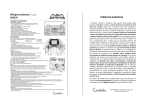
The HP-71B Computer (Fig. 1) is the latest entry in this
progression of increasingly more powerful handheld prod
ucts. In addition to retaining almost all of the capabilities
of its predecessors, it also can be programmed in a highlevel language, using its powerful built-in BASIC operating
system with over 240 keywords. The internal math routines
have 12-digit accuracy and conform to the proposed IEEE
floating-point math standard.4 All of the electronics, the
QWERTY-style keyboard with separate numeric keypad,
22-character liquid-crystal display, 64K-byte ROM operat
ing system, 17.5K-byte user RAM, and battery power sup
ply are contained in a 3% x 7V2 x 1-inch pocket-sized pack
age that weighs 12 ounces. (See article on page 17 for a
discussion of the packaging techniques used in the HP-71B.)
The HP-71B has four ports for adding RAM or ROM to
the mainframe, which has an address space of up to 512K
bytes. Currently, 4K bytes of RAM or up to 64K bytes of
Fig. 1. The HP-71B Computer is
HP's latest and most powerful
handheld computer. Intended for
use by the technical professional,
it can be used as a highly ad
vanced algebraic calculator and/
or as a computer using a built-in
240-keyword BASIC program
ming language. Four ports allow
addition of more RAM and/or ROM
to expand system memory and to
enhance the HP-71B's computa
tional power. An optional handpulled card reader module can be
added for local portable mass
storage and an HP-IL module can
be added for communication with
peripherals and instruments.
JULY 1984 HEWLETT-PACKARD JOURNAL 3
© Copr. 1949-1998 Hewlett-Packard Co.
RAD
fl=2.74*flTflN.C13.5/C5+l*
ROM can be added to each port. The HP-71B can be further
expanded by adding the optional handpulled 82400A Card
Reader Module for mass storage and the 82401A HP-IL
Interface Module for communication and control of
peripherals such as display monitors, cassette drives, print
ers, and instruments.5
To take full advantage of the capability within its com
pact package, the machine has two modes. CALC mode (see
box on page 6) is an algebraic calculator environment that
makes intermediate calculations easy. BASIC mode is an
environment in which programs can be entered, edited,
and run. These two modes share the same variables and
both have access to the many built-in math and statistics
functions. The statistics functions can handle data for up
to fifteen independent variables to calculate means, stan
dard deviations, correlations, linear regression, and pre
dicted values.
In all respects, the HP-71B is intended as a useful tool
for the technical professional. The design philosophy was
to provide the user with maximum capability wherever
possible. An example of this philosophy is the implemen
tation of variables. Variables remain intact until the user
explicitly destroys them. Hence, variables set from the
keyboard are available for use in programs. Also, the HP-71B
implements dynamic variable allocation, meaning that
users are freed from having to dimension arrays and allo
cate string variables at the beginning of their programs.
Within a program, a variable can be dimensioned and used
as an array, later destroyed (using the DESTROY statement),
and then used as a scalar or redimensioned as a larger or
smaller array. Dynamic variable allocation allows more ef-
CALC
Fig. 2. The HP-71B's liquid-crys
tal display provides a 22-character window into a 96-character
line. The pixels forming the
characters can be individually
read and controlled for program
input and special graphics output.
Display contrast and optimum
viewing angle can also be ad
justed for user convenience.
ficient RAM use, since a program can prompt for input
before variable allocation. In this way variables can be di
mensioned based on current user input demands, eliminat
ing wasteful RAM use based on worst-case (maximum an
ticipated size) variable allocation.
BASIC Language
While the HP-71B's custom four-bit parallel processor is
optimized for fast, accurate BCD (binary-coded decimal)
calculations, it is also well suited to minimize RAM re
quirements for BASIC code tokens. Each token occupies
one or more nibbles (a nibble is four bits), a RAM economy
more difficult to achieve with byte-oriented processors.
HP-71B BASIC allows multistatement lines for further op
timization of RAM use.
The BASIC operating system optimizes program branch
ing. Labels allow branching to any statement. Aside from
the added convenience and readability of labels, they are
maintained as a linked list to reduce search time. When a
line number reference is first encountered, the relative
offset to the referenced statement is stored so that sub
sequent branches are faster.
HP-71B BASIC provides a real-time clock and three tim
ers. Many of the programmable statements interact with
the clock and timers so that with the addition of the op
tional 82401A HP-IL Interface Module, the HP-71B is an
ideal choice for a low-cost, battery-powered controller.
The implementation of subprograms on the HP-71B helps
make it an especially powerful handheld computer. Param
eters can be passed to a subprogram by reference or by
value. Subprograms can be written in BASIC or HP-71B
Fig. 3. Keyboard of the HP-71B
Computer.
4 HEWLETT-PACKARD JOURNAL JULY 1984
© Copr. 1949-1998 Hewlett-Packard Co.
assembly language. (Assembly language subprograms offer
increased system access as well as faster execution.)
Whether the called subprogram is written in assembly lan
guage or BASIC, all variables and execution stacks in the
calling environment are preserved.
A useful subprogram feature in the HP-71B is recursive
programming. By allowing a subprogram to call itself, some
advanced calculations can be done much more easily.
Display
A one-line, liquid-crystal display (Fig. 2) provides a 22character window into a 96-character line. The display
consists of 132 columns of eight dots each, called pixels.
Each character displayed uses six columns. The sixth col
umn is blank for character spacing. The display contrast
and optimum viewing angle can be adjusted to one of 16
values for user convenience by using the CONTRAST com
mand.
The standard character set contains 128 characters and
an alternate set of 128 characters can be defined by the
user. This character set may reside in RAM or a plug-in
ROM, giving applications added flexibility in conveying
information through the display.
In addition to increasing the character set, the user can
take complete control of the pixels in the display. This
allows simple graphics and eye-catching patterns to be dis
played. It is also possible to read the pattern of pixels from
the display, modify the pattern, and then redisplay it. This
allows a number of useful applications to be written in
BASIC, including column scrolling and a graphics editor.
To work around the limitations of the small display,
special editing keys are included on the keyboard. These
keys allow character inserting, replacing, and deleting,
scrolling the 96-character line to the left or right, and delet
ing from the cursor position through the end of the line.
A command stack contains a history of the last five lines
entered, so that the display is actually a window into a
96-character-by-5-line field. It is possible, through BASIC,
to extend the command stack to 16 lines. The command
stack is a major factor in the user friendliness of the HP-71B
operating system, in that it allows easy error recovery, re
duces user keystrokes, and minimizes dependence on an
external monitor for editing large programs. For example,
if an operation generates an error, the user can recall several
lines to the display to determine what caused the problem.
Often, when the problem is recognized, only one or two
keystrokes are required to modify previous input, and using
the line editing keys, lines are easily edited and reentered.
The convenience of this becomes apparent when input
lines contain up to 80 or 90 characters.
Keyboard
The HP-71B has a QWERTY-style keyboard for al
phanumeric entry and a numeric keypad for convenient
entry of numerical data (Fig. 3). To simplify programming
and calculations, forty-two typing aids on the keyboard
cover the most commonly used BASIC keywords and math
and statistics functions. Accessed by using the gold f shift
key, these typing aids are arranged in logical groupings of
program branching, I/O, file management, trigonometry,
and statistics keywords. Coupled with the user's ability to
add or substitute typing aids with redefined keys (dis
cussed later), this holds user keystrokes to a minimum.
To further reduce user keystrokes, an implied DISPlay
statement was implemented. Implied DISP almost elimi
nates the need to type in the keyword DISP, even in state
ments embedded in multistatement lines.
Customization and Expansion
A major question faced by the design team was how to
build a useful handheld computer with maximum potential
for expansion and customization. Part of the answer was
to use LEX (language extension) files to extend and cus
tomize the operating system. LEX files do this in two ways.
First, they provide a means of adding BASIC keywords to
the operating system. Up to 256 keywords can be added
per LEX file, in addition to the keywords already available
in the base operating system and other LEX files. No capa
bility is sacrificed when adding keywords to the machine —
the operating system is just further enhanced. Second, LEX
files can contain machine language routines called poll
handlers that have an opportunity to respond when a par
ticular piece of operating system code is executed. For
example, poll handlers can be used to take over control of
the display and keyboard, add file types to the system, and
substitute local language messages for the existing English
ones, making it easy to adapt software on the HP-71B to
other languages. The challenge to the design team was to
provide the hooks, known as polls, in all the key parts of
the operating system so that the HP-71B could be cus
tomized for virtually any application.
Key Redefinition
Another design decision was to allow the keyboard to
be redefined. Every key on the keyboard, along with its
shifted definitions, can be redefined, except for the gold f
and blue g shift keys. There are three types of key redefini
tions. Two are typing aids. When these redefined keys are
pressed, the characters assigned to the key are added to
the display contents. One of the typing aids includes an
implied END LINE, so that whatever the redefined key enters
in the display line is then immediately executed. The third
type of key redefinition executes the operation assigned
to the redefined key without altering the display first. This
type of key redefinition is useful for emulating RPN (reverse
Polish notation) operation, in that a key can be redefined
to call a program that reads the display for input and then
performs the desired calculation. Then, all the user has to
do to use RPN is type the input and hit the redefined key.
A keyboard redefinition is stored in a special file, known
as a KEY file. For each application, a different KEY file can
be created. These files can be maintained in RAM or stored
on a mass storage medium such as a card. A particular KEY
file can be designated as the current keyboard configuration
whenever the corresponding application is being used.
File Management System
The HP-71B has a sophisticated file management system.
Its memory can contain multiple files — the number is lim
ited only by the amount of available RAM. The operating
system recognizes seven file types (BASIC, DATA, SDATA,
TEXT, LEX, BIN, and KEY), and allows LEX files to support
JULY 1984 HEWLETT-PACKARD JOURNAL 5
© Copr. 1949-1998 Hewlett-Packard Co.
Calculator Mode for a Handheld Computer
1 Flush input buffer
•Collapse operand stack
'Collapse operator stack
nfe
Push EOL on
operator stack
Decompile
(see Fig. 2)
Get character from
keyboard and append
to input buffer
•Flush input buffer
•Send error message
Yes
• Remove number from
input buffer
• Stack number on
operand stack
• Remove operator
from buffer
New
operator of
higher precedence
than top-of-stack
operator ?
No
Pop operator stack
• Execute operator
As a computer, the HP-71B speaks BASIC. But how should it
behave as a calculator? While BASIC allows the user to evaluate
arithmetic expressions freely, experience has shown that this
alone much unsatisfactory for experimental calculation — too much
is hidden by the process. And RPN (reverse Polish notation), thesimple but powerful language used by other HP calculators,
seems inappropriate on this machine because its format differs
from that used in BASIC expressions.
What's left? One possibility is the display-driven feedback loop
used by some other handheld computers. This system is based
on reparsing the contents of the machine's display buffer. It is
easy to explain to the user and it delivers intermediate results,
but all of the digits in those intermediate results must be in the
display if accuracy Is to be maintained. This is a very annoying
property in a scientific calculator.
As a better alternative, the HP-71B uses an operator-prece
dence parser with value substitution (OP/VS). It accepts standard
arithmetic expressions, just as BASIC does, but it evaluates them
as they are entered, maintaining 12-digit accuracy regardless
of the display setting. Also, it detects syntax errors in a very
forgiving way.
A simplified version of this algorithm is presented by the flow
charts shown in Fig. 1 and Fig. 2. The simplified parser outlined
in Fig. 1 recognizes expressions composed of integers and bi
nary operators. Functions, monadic operators, and parentheses
all add modest complications to the actual algorithm.
The use of OPA/S on the HP-71B Computer is called CALC
mode. Aside from showing intermediate results, it has several
helpful features that set it apart from other calculators:
• Delimiter anticipation. Hit the ( key and a matching closing
parenthesis is automatically entered in the HP-71B's display.
Mismatched parentheses cannot occur in CALC mode. Also,
CALC mode knows how many arguments a function requires.
When a function name followed by an opening parenthesis is
typed in, the correct number of commas are placed In the
• Clear display
• Copy input buffer to
right end of display buffer
Save stack pointers
Stack new operator
Pop operator stack
• Prefix popped operator
to display buffer
• Pop operand stack
•Prefix popped operand
to display buffer
Yes
Pop operand
stack to display
Restore stack pointers
f l
Fig. 1 . Flowchart for operator-precedence parser with value
substitution (OP/VS).
â € ¢
Fig. 2. Decompiler flowchart.
6 HEWLETT-PACKARD JOURNAL JULY 1984
© Copr. 1949-1998 Hewlett-Packard Co.
function's argument list in anticipation of the need for them.
Implied result. For instance, take the case where the user
calculates 4x5 + 10, and then decides to take the sine of
this result. CALC mode makes this easy, since it understands
empty parentheses to mean the previous result. For example,
using the HP-71 B's typing aid for SIN causes SIN() to be dis
played by the HP-71 B's liquid-crystal display; then pressing
the END UNE key causes the HP-71 B to calculate and display
the sine of the result of the previous calculation.
Backward execution. Experimental calculations are tentative;
the user frequently wants to undo something and then try
something else. Pressing the BACK key on the HP-71 B's
keyboard will undo as many operations as desired, one oper
ation per press of the key — all the way back to the beginning
of an expression. This feature was implemented at no cost in
additional types as needed.
The HP-71B gives users the capability to partition the
internal and plug-in RAM. Unless configured otherwise,
plug-in RAM automatically extends system RAM, which
contains not only files, but program control information,
saved environments, and variables as well. However, RAM
partitioned with the FREE PORT command is maintained
as a separate, independent entity with its own set of files.
RAM maintained in this way is called independent RAM.
Once a RAM is freed in this manner, files can be created
and edited on that RAM with the same commands that are
used to edit a file in system RAM; the operation is trans
parent to the user. Files can be copied from an independent
RAM to system RAM and vice versa. This memory parti
tioning can speed program execution in a number of ways.
When files in memory are referenced with their optional
location specifier, file search time is reduced. Having sev
eral smaller memory partitions instead of one very large
one minimizes time spent moving memory when files
change size or are purged. When the files on an indepen
dent RAM are no longer required and the RAM is needed
to extend system RAM, the CLAIM PORT command is used
to undo the FREE PORT command.
Dynamic memory movement, a complicated process to
implement in any machine, was further complicated by
the independent RAM capability. Every time files move
(purging a file or changing the size of a file), all affected
address references must be changed to reflect the new mem
ory layout. To accomplish this, a reference adjust routine
is called that adjusts all address references, including those
saved on execution stacks (FOR. ..NEXT loops, GOSUB) and
in saved environments. The algorithm for adjusting
addresses had to take into account several factors:
• There can be many different file chains in RAM config
ured at disjoint addresses.
• Commands executed from the keyboard are executed out
of a buffer that immediately follows the main file chain.
A command can be a multistatement line in which any
one or all of the statements cause files to move.
• A program can call a subprogram in another file, and
the calling program can move in memory or even be
purged.
• Any statement in a multiline user-defined function can
move memory.
Updating addresses was among the bigger software design
user RAM.
• Command stack, key definitions, and user-defined functions.
These features combine to make the HP-71 B's CALC mode
flexible and dynamic.
Acknowledgments
Special thanks to Eric Vogel, Bruce Stephens, and Frank Hall
for assistance with the development of CALC mode, and to Stan
Mintz for insisting that it be done.
Stephen Abell
Software Designer
(formerly a development engineer
at HP's Portable Computer Division)
challenges in making the user interface to files on indepen
dent RAMs friendly and transparent.
The added capability of independent RAMs required that
some file commands previously defined for the HP-75 Com
puter6 be extended and that some new commands be added.
For example, since files of the same name can exist simul
taneously in system RAM and in independent RAM, the
file catalog information indicates where in memory a file
resides. In addition, all file commands (COPY, PURGE, EDIT,
TRANSFORM, CAT, and LIST) allow an optional device
specifier to indicate which memory device is being refer
enced. The SHOW PORT command was added to display
information on all ROMs and independent RAMs config
ured in the system.
File Security
Included in the file management system are two levels
of file security — secure and private. The SECURE statement
allows users to protect their files from inadvertent modifi
cations; it guards users against making a mistake they may
regret. A secured file cannot be purged or modified, but
can be unsecured with the UNSECURE statement. On the
other hand, making a file private by executing the PRIVATE
statement prevents people from copying software that they
shouldn't have access to. A PRIVATE file can only be exe
cuted or purged; it cannot be modified or copied. Once a
file is made private, it remains so — privacy cannot be un
done. However, a PRIVATE file can be protected against
erasure by using the SECURE statement and later unsecured
by the UNSECURE statement so that it can be purged.
A global protection capability is also available by using
the LOCK statement. With this statement, a user can prevent
unauthorized use of an HP-71B by assigning a password.
Then when the HP-71B is turned on, it requests the pass
word, and if the entry is not correct, the HP-71B turns itself
off. The password can only be bypassed by clearing all
memory, in which case there is nothing left to protect.
The issue of security presented many design challenges.
Since the CLAIM PORT command destroys any files in the
independent RAM, special code was added so that use of
the CLAIM PORT command results in an error message if any
files in the RAM are secured. But the biggest challenge in
maintaining file security was related to the implementation
of the PEEKS and POKE commands. Supporting file security
from BASIC without PEEKS and POKE was easy. However,
JULY 1984 HEWLETT-PACKARD JOURNAL 7
© Copr. 1949-1998 Hewlett-Packard Co.
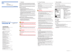
HP-IL Interface Module for the HP-71B Computer
The HP 82401 A HP-IL Interface Module is designed to comple
ment and extend the HP-71 8 Computer's capabilities by provid
ing a powerful, flexible I/O structure. HP-IL (Hewlett-Packard In
terface Loop) is Hewlett-Packard's standard serial interface for
portable, battery-powered computers.1 Major objectives for this
plug-in module were I/O speed, flexibility, and easy integration
with the HP-71 B electronics and operating system. The module
extends the print, display, and file transfer capabilities of the
HP-71 B, and provides a general I/O capability for use with instru
ments and other controllers, particularly in portable applications.
The 82401 A consists of a plastic case, HP-IL input and output
connectors, a custom eight-bit I/O processor, a 16K-byte ROM,
and discrete components to reduce EMI (electromagnetic inter
ference) and provide protection against damage caused by BSD
(electrostatic discharge). (See Fig. 4 on page 20 for an exploded
view of the HP 82401 A.) This package plugs into a recess in the
back of the HP-71 B. A 254-page user manual explains and illus
trates the use of the module and its software.
Module Architecture
A block diagram of the 82401 A HP-IL Module's architecture
is shown in Fig. 1 . The module's 8-bit I/O processor, which draws
its power from the HP-71 B mainframe, handles the HP-IL protocol.
This frees the HP-71 B's CPU from the chores of driving the loop,
thereby enhancing the overall speed of the system. The 1 6K-byte
ROM enclosed within the module provides keyword extensions
to the HP-71 B BASIC operating system. These keywords allow
the user to perform I/O operations such as device control, file
transfer, and remote operations. The software in this ROM also
provides support for up to three interface loops on the HP-71 B.
Secondary addressing provides I/O capability for using up to
930 devices on each loop.
The dual-CPU architecture combined with hardware optimized
for automatic retransmission of frames in the module's I/O proces
sor makes the HP-71 B one of the fastest HP-IL controllers to
date, with data transfer rates exceeding 5000 bytes per second.
I/O Processor
The module's I/O processor is an 8-bit CMOS microprocessor
with on-chip ROM, RAM, and custom I/O interfaces. A buildingblock design approach reduced development time and the
amount of external circutry required to support the module. The
major blocks in this microprocessor are the CPU, an 8-bit prescalable timer/counter, an interface to the HP-71 B system bus,
and an interface to the HP-IL transmitters and receivers.
The I/O processor's firmware allows a higher-level interface to
HP-IL than the traditional HP-IL Interface 1C.2 Rather than inter
facing to the loop at a frame-by-frame level, the module's I/O
processor enables the HP-71 B to send commands such as "Ad
dress the loop" or "Find a device of this class." Data and com
mands are passed between the two CPUs through an eight-bytewide mailbox, with each CPU controlling four bytes. Hardwareaided handshaking simplifies the message sending process.
The I/O processor provides input and output data buffers, each
about 65 bytes long. The I/O processor implements the loop
protocol until data is received or requested or an interrupt con
dition is met. By requesting service on the HP-71 B system bus,
the I/O processor signals the HP-71 B that one of these conditions
has occurred. The I/O processor maintains loop integrity — pow
ers up the loop, keeps the frame timeouts — and maintains various
loop conditions such as controller, talker, listener, and serial poll
responses. With this information tucked away in the I/O proces
sor, it is a natural extension to plug in another I/O processor,
enabling multiple HP-IL loops to reside on the HP-71 B.
Software
The module's 1 6K-byte ROM provides 50 keywords that extend
the HP-71 B BASIC operating system. Some are new keywords,
and others are extensions to existing commands. Syntax for the
keywords follows the I/O command syntax used on HP Series
80 and Series 200 Computers. File manipulation capabilities in
the HP-71 B are extended to work with HP-IL mass storage de
vices such as digital cassette and flexible disc drives. These
extensions allow files to be created, purged, read, written, and
protected. In addition, conversion between internal BASIC files
and TEXT files is extended to HP-IL mass storage devices. Files
specified in RUN and CHAIN statements are automatically copied
from HP-IL as required.
The COPY keyword has been extended to allow file transfers
to and from devices other than mass storage devices. This ability
to copy a file to and from an interface (e.g., HP-IL to HP-IB)
makes communication with other computers easy.
Start-Up
When the HP-71 B is powered up, the 82401 A scans the loop,
identifying the types and locations of printer and display devices.
Automatic PRINTER is... and DISPLAY is... assignments route
printer and display output to appropriate peripherals, freeing the
user from having to configure the machine manually to available
peripherals. The display output is tailored to match the type of
display device. For example, if a printer is assigned as the DIS
PLAY IS... device, the display output is sent after the user presses
the END LINE key on the HP-71 B. This avoids having any of the
previous editing sequences appearing in the printout. If the loop
is disconnected or the module is removed, output from PRINT
and DISP commands reverts to the HP-71 B's display.
Transmit Receive
Fig. 1. Block diagram of the architecture of the HP 82401 A
HP-IB Interface Module for the HP-71B Computer.
Addressing
Flexibility in creating an application is enhanced through the
implementation of six device specification modes. Two of these
modes indicate a specific location of a loop, three modes identify
a device by its name or device class, and the last refers to the
volume label of a mass storage medium. An example is the
specification of a device by describing its class. For instance,
8 HEWLETT-PACKARD JOURNAL JULY 1984
© Copr. 1949-1998 Hewlett-Packard Co.
the command COPY BUDGET TO TAPE will copy a file BUDGET
from the HP-71B's RAM to the first HP 821 61 A Digital Cassette
Drive found on the loop. The command CAT .MAIL will return
catalog information for the first mass storage volume found with
a volume label MAIL.
Instrument Control
Multiple keywords are provided to simplify finding, polling, and
setting up an instrument. All the various formatting options pro
vided by the HP-71B mainframe are available for use with the
HP-IL keywords for entering and outputting data. For special
applications, the user can control devices at a frame-by-frame
level.
The HP-71 B can act either as system controller or as a device
under the control of another computer on the loop. Keywords
provided in the module's ROM allow the user to exchange control
with other computers on the loop. An extension of this general
capability allows another controller on the loop to give commands
to the HP-71 B as if they were coming from its keyboard. If the
HP-71 B is off at the time a command is received by the I/O
processor, the HP-71 B automatically turns on to process the
once the decision was made to implement these two
keywords, security became very complicated. The execu
tion code for POKE contains many special checks to ensure
that a protected file stays that way. POKE does not alter a
protected file, but that alone is not sufficient. For example,
the HP-71B file chain is a linked list in which each file
header contains an offset to the next file in the chain. Hence,
a special check was added to the POKE routine to guard
against poking into the file length field. Otherwise, poking
a larger offset into the length field of an unprotected file
could make the following (possibly secured) file look like
part of the preceding unprotected file, allowing it then to
be poked at will.
Open Machine Concept and Documentation
The HP-71B is designed as an "open machine" to make
it easier for others to do customization and expansion. The
open machine concept is a statement of the design team's
objective to maximize the scope of applications addressable
by the HP-71B, acknowledging that individual users and
outside vendors will help accomplish this.
To support this concept, a full detailed set of documen
tation was developed — a three-volume IDS (Internal Design
Specification). The first volume contains information per
taining to the operating system design, such as data struc
tures, system RAM configuration, file header layout, expla
nations of statement parse and decompile, how to write a
LEX or BIN file, and how to write a poll handler. The second
volume contains information on every supported entry
point in the machine, including entry and exit conditions,
subroutine level use, and register use. The third volume
contains all the source code and documentation for the
entire 64K-byte operating system. The first two volumes
include a table of contents and an index.
As mentioned above, the PEEKS and POKE statements
were implemented to allow low-level interaction with the
operating system from BASIC. This is one of many areas
in which Volume I of the IDS can be a valuable resource.
command. In addition, the HP-71 B has the capability to recognize
and respond to interrupts from the HP-IL while it acts as a device.
This capability allows small-scale local area networking, resource
sharing, and multipoint data collection applications.
Acknowledgment
Steve Chou assisted greatly with the 1 6K ROM code for the
82401 A Module.
References
1 . R.D Quick and S.L. Harper, "HP-IL: A Low-Cost Digital Interface for Portable Appli
cations." Hewlett-Packard Journal. Vol. 34. no 1 , January 1983
2 S.L. ibid. "A CMOS Integrated Circuit tor the HP-IL Interface." ibid.
Nathan Zelle
Development Engineer
Portable Computer Division
Jackie Hunt
University of Colorado at Boulder
(formerly a development engineer
at HP's Portable Computer Division)
HP-IL
The optional 82401A HP-IL Interface Module (see box
on page 8) enables the HP-71B to interface with a variety
of peripherals at an enhanced data transfer rate of 5000
bytes per second, which is 25 times the HP-IL data rates
on the earlier HP-41C Computer. The function set available
in the 82401A eliminates any need for a separate I/O ROM
for the HP-71B.
Software
The software pacs currently available for the HP-71B
include Finance, Circuit Analysis, Surveying, Text Editor,
Curve Fit, Math, and FORTH/Assembler. The Finance Pac
has most of the functions of the HP-12C Calculator, with
its user interface modeled after the arrangement of the HP12C's top row of keys.
The Circuit Analysis Pac runs several times faster than
previous circuit analysis software written for HP's Series
40 and Series 80 Computers. In addition, it can handle
much larger circuits and is designed for use in a portable
environment.
The Surveying Pac has a friendly file management system
and solves for angular and linear relationships between
multiple coordinate points.
The Text Editor Pac allows easy editing of TEXT files and
provides formatting capability for any HP-IL printer, in
cluding Thinkjet. One of the many features of the formatter
is the ability to write a single letter or memo and then
specify a distribution list so that each document is per
sonalized as it is formatted.
The Curve Fit, Math, and FORTH/Assembler Pacs are
discussed in detail in the articles on pages 22, 24, and 37,
respectively.
Acknowledgments
Engineers who contributed significantly to the design
and implementation of the operating system include Janet
Placido, Bruce Stevens, Nathan Meyers, Steve Abell, Steve
Chou, Mark Banwarth, and Frank Hall. Stan Blascow, Paul
JULY 1984 HEWLETT-PACKARD JOURNAL 9
© Copr. 1949-1998 Hewlett-Packard Co.
McClellan, and Joe Tanzini implemented the mathematics
and built-in statistics. Richard Carone and Eric Evett were
very influential in the operating system design through
their guidance as project managers.
References
1. T.M. Whitney, F. Rodé, and C.C. Tung, "The 'Powerful Pocket
ful': an Electronic Calculator Challenges the Slide Rule," HewlettPackard Journal, Vol. 23, no. 10, June 1972.
2. C.C. Tung, "The 'Personal Computer': A Fully Programmable
Pocket May Hewlett-Packard Journal, Vol. 25, no. 9, May
1974.
3. B.E. Musch, J.J. Wong, and D.R. Conklin, "Powerful Personal
Calculator System Sets New Standards," Hewlett-Packard Journal,
Vol. 31, no. 3, March 1980.
4. W.J. Cody, et al, "DRAFT: A Proposed Radix- and WordlengthIndependent Standard for Floating-Point Arithmetic," IEEE Micro,
(to appear August 1984).
5. R.D. Quick and S.L. Harper, "HP-IL: A Low-Cost Digital Interface
for Portable Applications," Hewlett-Packard Journal, Vol. 34, no.
1, January 1983.
6. D.E. Morris, A.S. Ridolfo, and D.L. Morris, "A Portable Com
puter for Field, Office, or Bench Applications," Hewlett-Packard
Journal, Vol. 34, no. 6, June 1983.
Soft Configuration Enhances Flexibility of
Handheld Computer Memory
by Nathan Meyers
SEVERAL IMPROVEMENTS incorporated into the
custom CPU of the HP-71B Handheld Computer
have considerably enhanced the speed and utility
of this processor over those used in earlier HP handheld
products. Most notably, a new feature of the bus architec
ture — soft memory configuration — has greatly increased
the flexibility of the system. Soft configuration means that
some devices occupying the address space do not have
fixed locations; their addresses are assigned to them by the
CPU. Putting the responsibility on software for configuring
the system allows a tremendous amount of freedom in de
termining memory layout.
There are two categories of devices that occupy address
space: memory (RAM and ROM) and memory-mapped I/O
(input/output devices that use a small piece of address
space to communicate with the CPU). The HP-71B operat
ing system software is responsible for assigning addresses
to all such devices somewhere within the available 512Kbyte address space. This task is handled by a 1500-byte
routine that executes whenever the computer powers up,
cold starts, executes FREE PORT or CLAIM PORT commands,
or recovers from a module-pulled condition or an INIT se
quence.
The challenge in designing the memory configuration
software was to come up with a scheme that would offer
flexibility in the RAM/ROM mix, maximize the use of the
address space, allow for future device types to be defined,
and, of course, work within the electrical constraints of
the devices being configured.
Address Range
Device(s)
00000 to 1FFFF
Operating system ROMs
Card reader interface
Bit-mapped display and timers
RAM in display driver chips (1 .5K)
2COOO to 2C01 F
2E100to2E3FF
2F400to2FFFF
All other devices are soft-configured in the remaining ad
dress space. Specifically, memory-mapped I/O is config
ured in the space from 20000 to 2COOO, extensions to system
RAM (memory available to the user) are configured upward
from 30000, and ROMs are configured in the space remain
ing above the end of system RAM (indicated by a pointer
called RAMEND).
System RAM begins in the hard-configured RAM (the
exact address is a function of system requirements) and
extends upward according to how many additional RAMs
are available. An HP-71B with nothing plugged into its
four ports contains 16K bytes of soft-configurable RAM, so
system RAM extends to 37FFF.
System RAM contains a file chain (a linked list of files)
and buffer list built upward from low memory, and stacks
and variables built downward from high memory, as shown
in Fig. 1 . Each plug-in ROM contains a file chain that begins
+ 8 nibbles relative to the beginning of the ROM and is
structured exactly like the file chain in system RAM. ROMs
contain nothing analogous to the variables, stacks, and buf
fers stored in system RAM.
Electrical Behavior of Devices
Memory Layout
The HP-7lB's CPU and all other devices reside in a 1Mnibble (a nibble is half of a byte) address space that ranges
from hexadecimal address 00000 to hexadecimal address
FFFFF. Certain devices are hard-configured as follows:
Soft-configurable devices have data and control lines to
interface to the system bus and two additional lines, DAISYIN and DAISY-OUT, used to make the configuration scheme
work. These lines are used in a serial "daisy chain" to
establish an order as shown in Fig. 2.
10 HEWLETT-PACKARD JOURNAL JULY 1984
© Copr. 1949-1998 Hewlett-Packard Co.
RAMENO
Variables and Stacks
AVMEME I
Available Memory
System Space
Fig. 1. Organization of HP-7TB system RAM in the memory
address space. AVMEMS and AVMEME are pointers marking
the start and the end of the available RAM address space.
dress. Its configuration address must be on a boundary
corresponding to its internal address space. That is, a 1Kbyte RAM must be configured on a IK-byte address bound
ary. Electrically, the upper nine bits of its address serve as
a chip select address while the lower eleven bits serve as
internal addressing within its 2K-nibble space.
There are six daisy chains, called ports, in the HP-71B
(Fig. 3). The first one, port 0, runs through the 16K bytes
of built-in system RAM and then to the HP-IL port. DAISY-IN
to the first chip in port 0 is tied high. The next four chains
are those going to the four module ports in the front of the
computer; they are software-switchable lines from the CPU.
The last daisy chain, port 5, is a software-switchable line
from the CPU to the port for the optional card reader, allow
ing installation of soft-configurable devices in that port.
Configuration Design Challenges
Devices have two configuration states — configured and
unconfigured. When configured, a device occupies address
space and responds to normal memory-access instructions
(i.e., reads and writes). In this state, DAISY-OUT = DAISY-IN.
A configured device can be unconfigured by two bus com
mands: RESET, which unconfigures all devices, and
UNCNFG, which unconfigures a device at a specific address.
When a device is unconfigured, it does not occupy ad
dress space. In this state, its DAISY-OUT line is held low.
The device will respond to only two bus commands, and
only when its DAISY-IN line is high: ID, which causes the
device to supply a 5-nibble identification, and CONFIG,
which causes the device to become configured to a
specified address. These daisy-chain conventions ensure
that only the first unconfigured device on the chain re
sponds to these commands. By holding DAISY-IN high to
the first device, the software obtains the device's identifi
cation, then configures it and moves on to the next device.
In this way, all devices on a daisy chain are configured.
The ID command is an important part of the configuration
scheme, since it identifies the device's type, size, and other
pertinent information. The five digits supplied in response
to an ID command contain the following information:
• Nibble 0 = 14- Iog2 (size in K bytes) for memory (value
of 9 to F allowed for RAM, 7 to F allowed for other mem
ory) and = 18 — Iog2 (size in K bytes) for memory-mapped
I/O.
• Nibble 1 is reserved for future use.
• Nibble 2 = device type. 0 = RAM, 1 = ROM, 2 to E =
unassigned, and F = memory-mapped I/O.
• Nibble 3 is unassigned if memory. If memory-mapped
I/O, 0 identifies the HP-IL mailbox and 1 to F are Unassigned.
• Nibble 4's high bit is set if device is last in the daisy chain.
A device cannot be configured to just any arbitrary ad-
System Bus
Fig. 2. Soft-configurable devices in the HP-71B are con
nected in daisy-chain fash/on and each device has its own
control and data lines connected to the system bus.
The configuration software must determine which de
vices are present, where they should be configured and,
most important, how to preserve the integrity of the system
when the memory configuration is changed. Some of the
major challenges that had to be met during the development
of the configuration code are discussed below.
Determining what's out there. The code needs to have a
complete inventory of what devices are available before it
can decide how to configure the system. To get this infor
mation, the software performs an identification prepass, in
which it requests each chip's identification and then con
figures the chip to address 40000. First, all chips in port 0
are identified and configured; this is necessary because the
DAISY-IN line to that port cannot be turned off. Once all
port 0 chips are configured, the software energizes each
successive daisy chain and identifies and configures all
chips on that chain. A table is built in hard-configured
RAM that will be used to assign addresses later. Configuring
all devices to the same address at this time is not a problem
as long as the code does not try to access the devices. The
chips will later be unconfigured and reconfigured to their
assigned addresses.
The table does not contain one entry for every chip.
Instead, every sequence of identical chips in a module
results in one table entry. A 4K-byte RAM plug-in module,
for example, would have a table entry identifying it as
containing four IK-byte chips. An HP-IL module results in
two table entries — one for its ROM and one for its electronic
interface (mailbox). After the table is built, it is split into
three subtables: RAM, ROM, and memory-mapped I/O.
Each is handled differently. By processing the chips by
device type rather than by port number, the software is
fairly insensitive to a plug-in module's exact position.
RAMs needn't occupy adjacent ports to work properly. In
fact, the port number is not the most important factor in
determining a chip's address, as we shall see later.
Extending the user RAM. To be useful, the user RAM must
be a contiguous extension of memory from address 30000
(where hard-configured RAM ends). Given the configura
tion address boundary requirements mentioned above, this
presents some difficulty in assigning addresses.
To resolve this difficulty, the RAM subtable is sorted in
order of size — largest to smallest. Then addresses are assigned.
Since the RAM configuration begins at address 30000 and
JULY 1984 HEWLETT-PACKARD JOURNAL 11
© Copr. 1949-1998 Hewlett-Packard Co.
Port 0.00
Port 0.01
Module Port 1
Module Port 2
Module Port 3
Module Port 4
Card Reader Port 5
since all RAM chips must be 512X2" bytes (n = 0, 1, . . , 6),
this ensures that all RAM chips can be configured contigu
ously and on legal address boundaries. (The port number
is a secondary sort key. Devices with the same chip size
are configured in port number order.) For example, suppose
an HP-71B Computer contains the following RAMs:
Port 0: Built-in 16K-byte RAM in IK-byte chips.
Port 1: 4K-byte RAM module consisting of four IK-byte
chips.
Port 2: 16K-byte RAM module consisting of four 4K-byte
chips. (This is a theoretical example; at this time
there is no such module available.)
Port 4: 1 6K-byte module consisting of two 8K-byte chips
(also theoretical example).
For this case, addresses will be assigned as follows (re
member, this is a nibble-oriented address space):
30000 to 33FFF: First chip in port 4
34000 to 37FFF: Second chip in port 4
38000 to 39FFF: First chip in port 2
3AOOO to 3BFFF: Second chip in port 2
3COOO to 3DFFF: Third chip in port 2
3EOOO to 3FFFF: Fourth chip in port 2
40000 to 407FF: First chip in port 0
40800 to 40FFF: Second chip in port 0
47800
48000
48800
49000
49800
Port 0.03
Port 0.02
to 47FFF: Sixteenth chip in port 0
to 487FF: First chip in port 1
to 48FFF: Second chip in port 1
to 497FF: Third chip in port 1
to 49FFF: Fourth chip in port 1
At this early stage of the configuration code, the chips
are not yet configured to these addresses. These addresses
are merely written into the RAM subtable. The configuring
of chips to their assigned addresses occurs after all chips
in all subtables are assigned addresses. For continuity,
however, this article will continue to discuss the challenges
of system RAM configuration before moving on to other
types of devices.
Accommodating new RAM plug-ins. What if the user turns
off the machine and inserts additional RAM plug-ins? The
configuration code must be able to restore system integrity.
Therefore, the configuration tables are not thrown away
after the system configuration is completed. They are kept
in the configuration buffer area in RAM. The tables can
then be used to compare the old configuration to the new
configuration, and the code can determine what must be
HP-IL Port 0 4 —
Fig. 3. There are six daisy-chain
configurations in the HP-71 B labeled
as ports 0 through 5 as shown.
done to restore system integrity. For example, assume that
an HP-71B is configured with a 4K-byte plug-in memory
module in port 2, and that the memory is occupied as
shown in Fig. 4a. Now assume that the user turns off the
machine and plugs another 4K-byte module into port 1 and
a 1 6K-byte module consisting of two 8K-byte chips (theoret
ical device used for illustration purposes) in port 3. Follow
ing the configuration rules explained above, the memory
will now look as shown in Fig. 4b. Adding RAM introduces
"bubbles" into the memory that, in this example, disrupt
the integrity of both the file chain and the stack space. To
solve this problem, the configuration code compares the
old and new configuration tables and determines which
RAM devices are new (in new table but not in old table)
and which RAM devices are missing (in old table but not
in new table). If any devices are missing that were not
contained entirely in available memory, the computer per
forms a cold start (memory reset), since this is an unrecov
erable disruption of system integrity. If there are any new
devices, the configuration code rearranges the contents of
memory to restore integrity. By moving data around, it
effectively moves the bubbles into available memory (Fig.
4c). The code is general enough to handle any number of
new bubbles and restore system integrity properly.
Devising a method to remove RAM modules nondestructively and having a ROM-like RAM, with an independent
file chain similar to plug-in ROMs. These two challenges
are mentioned together because they have the same solu
tion. That solution is known as "independent RAM."
An independent RAM (IRAM) is treated like a ROM. It
is not configured as part of system RAM, and can therefore
be removed without destroying system integrity. It contains
a file chain just like a ROM, and any IRAM that can retain
data when unplugged (a technological possibility) can be
used to transfer programs between machines.
The user can designate any RAM to be an IRAM by
executing the FREE PORT command, and can unfree an
IRAM with the CLAIM PORT command. Since it is not pos
sible for the software to change a chip's identification (to
distinguish an IRAM from a RAM) , IRAMs are implemented
by writing a special sequence of 8 nibbles to the beginning
of a RAM module. When the configuration identification
code is executed as described earlier, each RAM module
is first configured to address 80000 and the first 8 nibbles
are read. If they match the special IRAM sequence, the
RAM is treated like a ROM; its table entry goes into the
ROM subtable and the module is not configured as system
RAM.
12 HEWLETT-PACKARD JOURNAL JULY 1984
© Copr. 1949-1998 Hewlett-Packard Co.
44000
•Theoretical example. 16K
RAM Module not available.
4K RAM in Port 2
42000
4K RAM in Port 1
40000
4K RAM in Port 2
38000
Built-in
16K RAM
(PortO)
30000
2F400
Variables
and
Stacks
42000
4K RAM in Port 1
Variables
and
Stacks
40000
^
Available
Memory
Built-in
16K RAM
(PortO)
Available
Memory
Available
Memory
Hard-Configured RAM
\
Built-in
16K RAM
(PortO)
3AOOO |
4K RAM in Port 2
— Variables
and
— Stacks
Programs
and
Buffers
16K RAM*
in Port 3
Programs
and
Buffers
30000
2F400
16K RAMin Port 3
30000
Hard-Configured RAM
(b)
2F400
Hard-Configured RAM
Programs
and
Buffers
(c)
Fig. module port HP-71B system RAM configuration with a 4K-byte RAM module plugged into port
2. (b) System RAM configuration after another 4K-byte RAM module is plugged into port 1 and
a theoretical 16K-byte RAM module (used for illustration purposes) is inserted into port 3. This
leaves gaps or bubbles in the address space which are then moved by the configuration
software to the available memory address space as shown in (c).
When the user frees a RAM module, the FREE PORT soft
ware verifies that there is enough available memory to re
move the RAM. If so, it rearranges memory to exclude the
designated RAM, writes the 8-nibble IRAM sequence to it,
marks the old configuration table to indicate that this RAM
was deliberately removed (so that a cold start will not be
performed when the RAM is discovered missing) and exe
cutes the configuration software.
This ends the discussion of system RAMs. The problems
of configuring ROMs and memory-mapped I/O are much
more straightforward. As with RAMs, the software builds
tables indentifying which ROMs and memory-mapped I/O
devices are plugged in. The main purpose of these tables is
to record where everything is so, for example, the HP-7lB's
operating system can locate all of the file chains or the
82401A HP-IL Module's software can determine where its
mailbox is configured.
Configuring ROMs efficiently in the remaining address
space. In all discussion here, "ROM" is shorthand for all
memory devices that are not used as system RAM: ROM,
IRAM, and any possible future memory types.
Unlike system RAM, ROM has much looser requirements
for what goes where. The only restriction is that identical
devices in a plug-in be configured together in daisy-chain
order. In other words, a 32K-byte ROM module containing
two 16K-byte chips must be configured with the chips next
to each other in the address space — this keeps the file chain
in one piece. There is, however, also a need to use address
space efficiently in configuring ROMs. ROMs can get quite
large, and 512K bytes of address space is easy to use up.
The configuration software handles the problem by sorting
the ROM subtable by size (as with RAMs) and configuring
from largest to smallest.
Unfortunately, simply configuring upward from RAMEND
is usually not possible, since RAMEND will not, in general,
occur at a legal configuration address for a large ROM. So
the software breaks the ROM configuration into two parts:
1. For large chips (32K bytes and larger), the software con
figures the module at the highest legal configuration
address that will hold it. So a 96K byte ROM module
consisting of three 32K-byte chips will be configured at
the highest 32K-byte address boundary that is capable
of hosting 96K bytes of contiguous memory without
configuring over something else (such as the operating
system ROM or other large chips).
2. For small chips (16K bytes or less), modules are config
ured contiguously in the holes remaining after the large
chips are configured.
Configuring memory-mapped I/O devices. These are de
vices that occupy address space, but are not memory. The
HP-IL mailbox is an example; it occupies 8 bytes of address
space that the CPU reads from or writes to when performing
HP-IL operations. To meet this need, a separate part of the
address space (20000 to 28FFF) is designated for use by
memory-mapped I/O. The sizes handled here are very dif
ferent from those of memory. Memory-mapped I/O devices
typically occupy only 8, 16, or 32 bytes of address space.
To make efficient use of the available address space, mem
ory-mapped I/O devices are configured in order of their
size (as with system RAM).
Configuring everything in daisy-chain order alter addresses
are assigned. The three subtables are merged and sorted by
port number and daisy-chain position. The software then
steps through the tables, configuring each device to its as
signed address. The subtables are once again separated and
saved in the configuration buffer area for future reference.
Acknowledgments
The HP-71B bus architecture, including the feature of
soft configuration, was conceived by James P. Dickie and
David M. Rabinowitz of HP's Personal Computer Division.
JULY 1984 HEWLETT-PACKARD JOURNAL 13
© Copr. 1949-1998 Hewlett-Packard Co.
Custom CMOS Architecture for a Handheld
Computer
by James P. Dickie
THE ELECTRONICS SYSTEM for the HP-71B Com
puter is based on seven custom CMOS integrated
circuits and a liquid-crystal display (LCD) designed
into a package that allows users to customize the HP-71B
easily to their needs. A simplified block diagram of the
mainframe system is shown in Fig. 1. The system is batterypowered, requiring no power supply, and consists of a CPU
and three display drivers mounted on the underside of the
keyboard/display printed circuit board. A four-chip 64Kbyte ROM hybrid and four 4K-byte RAM hybrids are
mounted on the I/O printed circuit board. The four RAM
hybrids in combination with the 1.5K bytes of display
driver RAM provide 17.5K bytes of built-in RAM. Connec
tions to the four RAM/ROM ports in the front of the HP-71B
and the HP-IL (Hewlett-Packard Interface Loop) port in the
back of the machine are made via the I/O printed circuit
board. The port for the optional card reader connects to
the keyboard printed circuit board.
The CPU was designed and optimized for use in hand
held computer products. It uses a 64-bit internal word size,
operates on a 4-bit data path, and uses 20-bit addresses to
provide a 512K-byte address space (the largest available in
this size of machine). The large address space eliminates
the problem previous systems had in bank-switching ROMs
and RAMs to obtain a larger memory space. The instruction
set is based on the style of architecture used in the HP-41C
Computer1 and is oriented toward the arithmetic nature of
handheld calculators with the capability of both hexadec
imal and binary-coded decimal (BCD) arithmetic.
The CPU incorporates two functions normally delegated
to support chips — keyboard control and clock generation.
The keyboard logic consists of a general-purpose input reg
ister (16 lines) with interrupt capability and a general-pur
pose output register (12 lines). The output register is also
used to drive the daisy chains to each port (see article about
memory configuration on page 10) and, in combination
with at circuitry, to drive the piezoelectric beeper at
one of two selected audio levels.
Three display driver ICs drive the 8-row-by-136-column
(including annunciators) liquid-crystal display. One of
these three drivers acts as the master and generates the
display clock, the voltage reference, and the display-on
signal used by the other two display chips (slaves). A 4-bit
software-controlled register modifies the display contrast
and optimum viewing angle by adjusting the value of the
voltage reference signal. The master/slave function and ad
dressing of a display driver chip are selected by two con
figuration pins that are tied high or low on the printed
circuit board. Each driver chip supplies 512 bytes of hardconfigured RAM and a 24-bit crystal-controlled oscillator
timer with Vsiz-second resolution. The timers are used by
the HP-71B's operating system to implement the real-time
clock system.
The optional 82400A Card Reader Module provides the
HP-71B Computer with inexpensive mass storage. The
handpulled magnetic cards can each record up to 1300
bytes. The card format and modified frequency modulation
(MFM) coding are the same as that used by the internal
card reader of the HP-75 Computer,2 which allows an inter
change of TEXT files recorded with the HP-75 "s LIF 1 format.
The 82400A consists of a two-chip hybrid, the external
components for the analog circuit, and a three-coil mag
netic head in a self-aligning mount. The analog 1C, which
is a modification of the 1C2'3 used by the HP-75 's card
reader, receives signals from the head and converts them
to digital signals. The hybrid digital 1C converts the seri
al MFM coding into data bytes and buffers them for the
HP-71B.
The 82401A HP-IL Interface Module (see box on page 8)
provides the HP-71B with high-speed I/O and the capability
To the
Ports
Input Output
Register Register
Fig. 1. Simplified block diagram
of the HP-71B mainframe system
electronics.
14 HEWLETT-PACKARD JOURNAL JULY 1984
© Copr. 1949-1998 Hewlett-Packard Co.
to drive the whole line of HP-IL peripherals. This module
is the first HP-IL interface that supports the entire HP-IL
definition in the base configuration. Using primary address
ing, up to 31 peripherals can be controlled, and up to 930
peripherals can be controlled through secondary address
ing. The 82401A is designed to allow the HP-71B to be a
loop device or controller as well as an interface for up to
three loops.
The 82401A consists of a two-chip hybrid containing a
16K-byte ROM and a newly designed I/O processor that
allows block communication transfer rates in excess of
5000 bytes/s. Also included are discrete components re
quired for isolation, electrostatic discharge (BSD) protec
tion, and impedance matching.
System Bus
The HP-71B bus structure was developed for use in hand
held computer products. The structure maximizes the per
formance of the system while minimizing the interconnect
required for each system 1C or port.
The system bus is a fully multiplexed 4-bit address, in
struction, data, and command bus. In addition, there are
two control signals — a bus clock *STR (also referred to as
strobe) and a command/data signal 'CD. The bus commands
used by this system are listed in Table I. *STR is driven by
the CPU and serves to synchronize all bus transfers. *STR
is not a true system clock, since it can remain inactive
(high) for cycles when the CPU is busy performing internal
operations. The *CD line indicates whether data on the bus
is a command (*CD low) or data {*CD high). In addition,
memory devices may have two other lines: DAISY-IN and
DAISY-OUT. The architecture of this system allows memory
to be located dynamically in the overall address space of
the CPU (512K bytes) and these two lines are used during
the address assignment process (soft configuration, see ar
ticle on page 10).
All bus operations are initiated by the CPU. The CPU
starts a specific transfer on the bus by driving the *CD line
low before *STR goes low. While *CD and *STR are low, the
CPU drives a command on the bus and all devices in the
Table I
HP-71B System Bus Commands
C o d e
M n e m o n i c
A c t i o n
0 NOP All devices ignore *STR until a new com
mand is loaded.
1 ID The unconfigured device that sees its
daisy-chain input high sends its fivenibble identification code on the
following data strobes.
2 PC READ Read using program counter. The device
selected by the system program count
er sends data addressed by its local pro
gram counter on the following data
strobes. AH devices increment their
local program counters each data strobe.
3 DP READ Read using data pointer. The device
selected by the system data pointer
sends data addressed by its local data
pointer on the following data strobes.
All devices increment their local
data pointers each data strobe.
4 PC WRITE Write using program counter. The de
vice selected by the system program
counter loads the data on the following
strobes into the location addressed by
its local program counter. All devices
increment their local program counter
each data strobe.
5 DP WRITE Write using data pointer. The device
selected by the system data pointer
loads the data on the following data
strobes into the location addressed by
its local data pointer. All devices
increment their local data pointer each
data strobe.
6 LOAD PC Load program counter. All devices
load the data on the following data strobes
into their local program counter, loworder nibble first. After all five nibbles
are transferred, the command code is
automatically changed to 2.
LOAD DP
CONFIG
UNCNFG
POLL
B
C
BUSCC
SHUTDOWN
RESET
Load data pointer. All devices load
the data on the following data strobes
into their local data pointers, low-order
nibble first. After all five nibbles are
transferred, the command code is auto
matically changed to 2.
The unconfigured device that sees its
daisy-chain input high loads the follow
ing five data nibbles into its configura
tion register, low-order nibble first.
The device currently addressed by its
local data pointer unconfigures itself.
The device then responds to CONFIG
and ID commands only. The local
data pointers must be loaded imme
diately preceding an UNCNFG
command.
All chips that require service pull one
data line high during the next *STR low.
Reserved
The device currently addressed by its
local data pointer performs a special
ized operation as defined by the indi
vidual device.
Reserved
When the CPU has received a SHUTDN
instruction it issues this command and
turns off its oscillator. Each device
responds based on its own special
requirements.
All devices reset their configuration flags
(if applicable) and perform other local
resets based on their own special require
ments.
JULY 1984 HEWLETT-PACKARD JOURNAL 15
© Copr. 1949-1998 Hewlett-Packard Co.
system latch the command on the rising edge of *STR. This
strobe is referred to as a command strobe. The command
issued during a command strobe specifies the operation
that is to be performed on each succeeding *STR until
another command is issued. At all times when data or an
address is being transferred, *CD is held high. A strobe
issued while *CD is high is referred to as a data strobe.
Addressing
Each device that resides on the HP-71B system bus has
two 20-bit address registers — the local program counter
and the local data pointer. A device responds to data reads
and writes only if its local address register (program counter
or data pointer depending on the read or write command)
is within its address configuration. Only the address of the
first nibble of data to be transferred needs to be sent, since
both the program counter and the data pointer are capable
of incrementing once each data strobe. This greatly reduces
the movement of addresses on the bus. Each device is either
permanently addressed (hard-configured) at a specific ad
dress or capable of being dynamically located (soft-confi
gured) at many addresses.
A soft-configurable device also has an ID register and a
configuration register. The ID register is a 20-bit read-only
register programmed to provide device specific information
required to identify its classification (RAM, ROM, memorymapped I/O, etc), memory size, and in some cases, posi
tional information (such as last device in a module). The
configuration register is up to 20 bits in length and positions
the device within the system memory space. The actual
size of this register is determined by the number of upperorder bits required to specify the device completely.
The HP-71B's operating system allows soft-configured
devices to have address spaces ranging in size from 8 bytes
to 128K bytes. All devices are configured such that the
upper-order bits of the local address register are compared
with the upper-order bits of the device configuration regis
ter (hard or soft). If these bits are identical, the device has
an address match and responds to read and write com
mands. The number of upper-order bits compared is deter
mined by the number required to specify the device's mem
ory size within the total address space. For example, a
device with an address space size of IK bytes (2K nibbles)
requires eleven bits of address, leaving the upper nine bits
for its configuration address.
Configuration
A soft-configured device powers up unconfigured. When
unconfigured, a device only responds to the ID and CONFIG
commands and drives its DAISY-OUT line low. The ID com
mand identifies a device before it is configured in the sys
tem. If a soft-configured device is unconfigured and sees
its DAISY-IN line high, it outputs its five-nibble identification
code (low-order nibble first) on the five data strobes that
follow the ID command.
A soft-configured device is assigned its configuration
address by the CONFIG command. If an unconfigured device
sees its DAISY-IN line high, it loads the configuration address
issued on the five data strobes immediately following the
CONFIG command (low-order nibble first) into its configura
tion register. A device may latch only the number of high-
order bits it requires as determined by its memory size. On
the following command strobe, the device sets its config
uration flag.
Once configured, a device no longer responds to either
an ID or a CONFIG command, and drives its DAISY-OUT line
to the same logic level as its DAISY-IN line. The DAISY-OUT
line of one device may be tied to the DAISY-IN line of a
second device. In this manner many devices are daisychained together so that they are configured individually
to different addresses. After being configured, a device
waits until the next command strobe to set its configuration
flag. This delays the change in its DAISY-OUT line so that
the next device on the daisy chain is not configured
simultaneously.
A device may be unconfigured by either a RESET or an
UNCNFG command. The RESET command simultaneously
unconfigures all soft-configured devices in the system. A
device responds to an UNCNFG command by clearing its
configuration flag if the data pointer is within its address
configuration.
A hard-configured device powers up configured to a spe
cific address and does not respond to an ID, CONFIG, or
UNCNFG command. A RESET command does not affect its
configuration. If the device has a DAISY-OUT line, it is always
driven to the same logic level as its DAISY-IN line.
Data Transfers
The CPU reads the contents of a specific address location
by first sending a LOAD PC or LOAD DP command followed
by the five-nibble address. The address is sent, least-signif
icant nibble first, with the data being latched on the rising
edge of *STR. After the last address nibble is loaded, the
command automatically changes to a PC READ or DP READ
and the addressed device sends one nibble each strobe.
The CPU may also perform a read without sending a new
address by issuing a PC READ or DP READ command. The
addressed device responds by sending one nibble each
strobe.
The CPU writes the contents of a specific addressed lo
cation in a similar manner. The address need not be loaded
before a write operation. A write is performed by issuing
a PC WRITE or DP WRITE command followed by the data to
be written. If the address is required before the write oper
ation, the CPU issues a LOAD PC or LOAD DP command
followed by the five-nibble address. After the address is
loaded, the CPU issues a PC WRITE or DP WRITE command
and places the data to be written on the bus.
All devices increment their local address registers once
each data strobe during read and write operations. It is
possible for a read or write operation to begin in one device
and cross the address boundary into another device. Cur
rently the CPU reads or writes up to 16 nibbles during an
operation, but the architecture allows reading and writing
more than 16 nibbles at a time.
Shutdown and Wakeup
The CPU has two fundamental states — operating and
standby. To place the CPU in standby mode, a SHUTDN
instruction is issued. The CPU sends the SHUTDOWN com
mand and on the ensuing cycle stops the system clock
(*STR) and its own clock. In standby mode, all CPU-resident
16 HEWLETT-PACKARD JOURNAL JULY 1984
© Copr. 1949-1998 Hewlett-Packard Co.
and system memory is preserved.
The CPU is brought out of standby mode either by pulling
an input register line high (pressing a key), or by driving
the *CD line low. On wakeup the CPU starts its clock and
immediately drives "CD low with a NOP command. If the
CPU detects that a severe low-voltage condition has oc
curred while it was in standby mode, the CPU program
counter is forced to zero and hexadecimal mode arithmetic
is asserted. A LOAD PC is the first command issued after
the NOP command and the current CPU program counter
value is loaded into all devices' local program counters.
At this point, the standard instruction fetch sequence is
initiated. If the CPU was awakened by an input register
and interrupts are enabled, then a normal interrupt occurs
before an instruction fetch.
*CD is driven low to wake up the CPU by a device in the
system that needs service while the system is in standby
mode. If a device wakes up the CPU and the CPU shuts
down without satisfying the device's need for service, the
device may not wake up the CPU again until the service
request has been satisfied. This avoids a situation where
the operating system does not know how to handle a de
vice's service request and therefore is not allowed to shut
down.
Service Poll
If a device needs service while the CPU is operating, it
must either wait until the CPU executes a service request
instruction (SREQ), or if it has the capability, interrupt the
CPU using IR14 (available at all ports). The SREQ instruction
causes the CPU to issue a POLL command, followed by one
data strobe during which the CPU latches the bus data in
the manner of a usual read. A device may respond to the
service poll by pulling one of the bus lines high. Since the
CPU precharges the bus low every cycle before *STR goes
low, the data read by the CPU is a binary OR of all device
responses.
The following HP-71B devices can wake up the CPU and
can respond to a service poll on the bus line shown:
Device Bus Line Service Request
Display Driver BUS[0] Timer underflow
HP-ILChip BUS[1] Data available, interrupt,
power-on reset, loop ser
vice request
Card Reader BUS[2] FIFO (first in, first out)
servicing, error condition.
Acknowledgments
There were many engineers who made significant con
tributions to the development of the electronics for the
HP-71B. Among these, Dave Rabinowitz made valuable
contributions to the bus architecture and CPU definition,
Dan Rudolph designed the display driver 1C, C. T. Wang
designed the RAM 1C, Van Walther designed the ROM,
John McVey characterized the CPU and pushed it into pro
duction, Bob Puckette became our ESD/EMI expert, and
Carl Johnson provided overall system support. The HP
82400A Card Reader Module was developed by Megha
Shyam, Bill Saltzstein, and Loren Heisey. A family of I/O
processors that include the processor for the 82401 A HP-IL
Interface Module was developed by Dave Rabinowitz,
Grant Garner, Don Reid, Dave Serisky, Preston Brown, and
Charles Brown.
A special thanks to the many people in HP's Corvallis
Components Operation who made significant contribu
tions to the support of the ICs designed. These include
Max Schuller, Tim Hubley, Bob Dunlap, Mike Gilsdorf,
Dane Rogers, Stan Gibbs, Scott Linn, Jim Hutchins, Joe
Szuecs, Von Soutavong, Doug Peck, Gary McDaniel, and
the rest of the packaging and fab personnel who made major
efforts to help the project succeed.
References
1. B.E. Musch, J.J. Wong, and D.R. Conklin, "Powerful Personal
Calculator System Sets New Standards," Hewlett-Packard Journal,
Vol. 31, no. 3, March 1980.
2. K.R. Hoecker, et al, "Handpulled Magnetic Card, Mass Storage
System for a Portable Computer," Hewlett-Packard Journal, Vol.
34, no. 6, June 1983.
3. T.J. Arnold and B.E. Thayer, "Integration of the HP-75's Handpulled Card Reader Electronics in CMOS," ¡bid.
Packaging the HP-71 B Handheld Computer
by Thomas B. Lindberg
THE PACKAGING OF THE HP-71B COMPUTER is
heavily based on the proven designs of the HP Series
10 Calculators and the earlier HP-75 Computer.1 The
styling follows a similar horizontal format, offering a block
QWERTY keyboard with a numeric pad on the right side.
Fig. 1 shows an exploded view of the HP-71B and identifies
many of the components discussed below.
Mainframe
The HP-71B mainframe is formed by two subassemblies:
the top case assembly and the bottom case assembly. The
two subassemblies are electrically connected by a flexible
circuit, which is reflow soldered in place using focused
infrared light. As with the HP-75 Computer and the Series
10 Calculators, aluminum overlays in the case halves are
JULY 1984 HEWLETT-PACKARD JOURNAL 17
© Copr. 1949-1998 Hewlett-Packard Co.
Top Case .
LC Display •
Keycaps
Jl • n • II II • • • n n ii ii
" - « " «I»
-"It : ill : «--I» : I» ' I*
Snap-Disc
Key Contacts '
Protective
Membrane
Keyboard/Display
Board
Motherboard -
HP-IL Module
Bottom Case
Battery
Compartment
Fig. packaging The view of the HP-71B Computer showing the various packaging features. The
mainframe is composed of two subassemblies: the top case assembly and the bottom case
assembly. The top case assembly contains the keyboard, display, and CPU and display driver
circuitry. The bottom case assembly contains the built-in memory, power circuits, and piezoelec
tric and and accommodates the optional card reader/recorder and other plug-in modules.
18 HEWLETT-PACKARD JOURNAL JULY 1984
© Copr. 1949-1998 Hewlett-Packard Co.
Fig. 2. Exploded view of a typical plug-in module for the
HP-71B. The ROM is surface-mounted on the underside of
the printed circuit board in the center.
used to provide parallel ground planes for effective shield
ing of the CMOS circuitry against electromagnetic interfer
ence and electrostatic discharge.2
The top case assembly consists of the keyboard and the
liquid-crystal display. The CPU, display drivers, and clock
circuitry are mounted in this subassembly. The bottom case
assembly contains circuitry for handling both ac and bat
tery power, as well as all ROM and RAM. Besides the
battery compartment and piezoelectric beeper, the bottom
case assembly provides four ROM/RAM module ports, a
card reader port, and an HP-IL (Hewlett-Packard Interface
Loop) interface module port. When installed, these op
tional modules are fully contained within the HP-7lB's
mainframe to maintain its compact silhouette.
The injection-molded keycaps are separated from the
underlying key contacts by an elastomer membrane to en
hance tactile feedback and to protect the underlying cir
cuitry from dust. The key contacts for the keyboard are
based on snap discs connected in a daisy-chain fashion.
The display is mounted to the printed circuit board using
elastomeric connectors and a rigid stainless-steel clip for
mechanical shock protection, a method similar to that used
on Series 10 Calculators.
The custom 4-bit chip set plays a significant role in the
mechanical packaging. A typical 8-bit computer system
would require at least 30 signal lines to connect the stan
dard ICs required. With HP's custom chip set, eleven sig
nals provide the same interconnection function, allowing
trace routing and connections to be made with fewer lines.
The high-pin-count CPU and display drivers use the same
flatpack surface-mounted-device packages developed for
the Series 10 Calculators. The low-pin-count RAM, ROM.
card recorder, and HP-IL ICs use the hybrid packaging
method developed for the HP-41C Handheld Computer.3
In the top case assembly, the display and key contacts
cover a major portion of the printed circuit board, restrict
ing the use of discrete components and leading to the ap
plication of surface-mounted devices. A total of eleven sur
face-mounted resistors, capacitors, and inductors plus four
ICs packaged in 72-lead flatpacks are placed on this board.
Placement is done by a robot using optical registration to
improve location tolerances and reduce the need for man
ual touch-up. Silk-screened polymeric resistors are used
for electrostatic discharge protection of the key contacts,
an application where these components' loose resistance
tolerances do not affect performance.
Twenty 1C chips are mounted in the bottom case assem
bly to provide the HP-71B's built-in 16K RAM and 64K
ROM. The memory density requirement in the available
6.1-cm-by-2.6-cm area exceeds the capabilities of dual in
line and/or flatpack packages, and hence requires the use
of hybrid packaging. Four ICs each are chip-on-board
mounted on the same polyimide hybrid boards designed
for use in the plug-in memory modules. These hybrid subassemblies are stacked on the motherboard, with their
phosphor-bronze pins inserted like single in-line packages.
Other lead components are also loaded before the entire
motherboard is drag soldered.
Plug-In Modules
The optional plug-in memory modules presented the
challenge of how to stuff a maximum number of memory
chips into a rugged package with a total volume less than
6 cubic centimeters. The same hybrid subassemblies used
for the mainframe memory are employed with berylliumcopper spring contacts for the electrical connection to the
Fig. 3. Exploded view of the op
tional 82400 -A Card Reader Mod
ule for the HP-71B.
JULY 1984 HEWLETT-PACKARD JOURNAL 19
© Copr. 1949-1998 Hewlett-Packard Co.
Fig. 4. Exploded view of the
82401A HP-/L Interface Module
for the HP-71B.
mainframe. The hybrid subassembly (Fig. 2) with one to
four memory chips — up to 4K bytes of RAM or 64K bytes
of ROM per module — is encased in plastic by ultrasonic
welding.
Card Reader/Recorder
The optional 82400A Card Reader Module (Fig. 3) pro
vides an inexpensive and highly portable mass memory
for the HP-71B mainframe. Handpulled magnetic strips
(cards) are the storage medium. A one-piece housing that
also serves as the card guide allows alignment of the mag
netic head without adjustment. Although the basic card
reader design was originally developed for the HP-71B, the
first version appeared in the HP-75 Computer.4 Both de
signs use the same head and magnetic cards with pre
recorded timing tracks. Battery life is conserved since these
tracks eliminate the need for the constant read/write speed
previously provided by a motor. In addition, the card bit
density of 315 flux reversals/cm is roughly double that of
HP's earlier motor-driven readers. The packaging makes
extensive use of surface-mounted components, which are
placed by a robot and vapor-phase reflow soldered. The
entire mass storage device with 20 discrete components,
two hybrid-packaged ICs, magnetic head, and connectors
occupies a volume less than 35 cubic centimeters.
HP-IL Module
The 82401A HP-IL Interface Module (Fig. 4) provides
the interface between the HP-71B's 4-bit mainframe bus
and HP's serial loop for interfacing portable devices. Hy
brid packaging is necessary to achieve the high functional
density. Two ICs are mounted chip-on-board along with
eleven lead and surface-mounted components on a 3-cmby-3.5-cm printed circuit board. The circuit board assembly
is enclosed by ultrasonically bonded plastic and a stainlesssteel cover. The total module volume is 20 cubic centimeters.
liquid-crystal display assemblies have all been previously
used at this HP Division, they have not all been used on
the same assembly. It is the combination of these
technologies that makes the HP-71B Computer the most
powerful computing device for its size.
Acknowledgments
There are countless people who made the idea of the
HP-71B become a reality. Special appreciation is directed
to the following for their major contributions. The indus
trial design of the product was done by Ed Liljenwall. Russ
Paglia, assisted by Marc Baldwin, did the initial mainframe
design. The design was further developed by Allen Wright
and Jerry Steiger. The memory module design was done
by Allen Wright and developed by Jerry Steiger and Dave
Smith. The HP-IL module design by Glenn Goldberg was
refined by Larry King. The card reader was designed by
Tom Hender. Thanks is extended to John Mitchell and his
tooling group for their major support during the project.
References
1. L.S. Mason and G.G. Lutnesky, "Packaging a Portable Comput
er," HewieÃ-Ã--Packard Journai, Vol. 34, no. 6, June 1983, p. 12.
2. G.J. May, "Electrostatic Discharge Protection for the HP-75,"
ibid, p. 14.
3. J.H. Fleming and R.N. Low, "High Density and Low Cost with
Printed Circuit Hybrid Technology," Hewlett-Packard /ournai,
Vol. 31, no. 3, March 1980.
4. K.R. Hoecker, et al, "Handpulled Magnetic Card, Mass Storage
System for a Portable Computer," Hewlett-Packard /ournai, Vol.
34, no. 6, June 1983.
Summary
With the exception of the silk-screened polymeric resis
tors, none of the design techniques or manufacturing pro
cesses are actually new to HP's Portable Computer Division.
Instead, the packaging of the HP-71B represents a refine
ment of the existing technologies. For example, while
vapor-phase soldering, snap-disc keyboards, and crimped
20 HEWLETT-PACKARD JOURNAL JULY 1984
© Copr. 1949-1998 Hewlett-Packard Co.
Authors
July 1984
designing the CPU for the HP-71 B Computer. Jim
is now project manager for the HP-71 B and his
work on its bus architecture has resulted in one pat
ent application. He is married, has two daughters,
and lives in Corvallis. Oregon. Outside of work, he
enjoys gardening, running, Softball, and sports in
general. Most recently, he has become an avid
skier
3 = New Handheld Computer Susan L Wechsler
1 7 H Z
i Susan Wechsler graduated
from California State Uni
versity at Long Beach with
a BA degree in mathema
tics in 1979. She came to
! HP in 1 980 and was a major
contributor to the design
and implementation of the
operating system for the
HP-71 B Computer. She
currently is working on application software for the
HP-71 B and new calculator R&D. Now living in Corvallis, Oregon, Susan says that she was born in
"beautiful downtown" Burbank, California. Her in
terests include jogging, stained glass, sewing, and
canning and drying fruit from her apple, plum, and
cherry trees.
P a c k a g i n g
D e s i g n
~
Thomas B. Lindberg
I^^J Tom Lindberg is an R&D
^Ã^^^^L. engineer working on pack
aging and interconnect
technology at HP's Porta
ble Computer Division. He
joined HP in 1981 after re
ceiving a BS degree in
mechanical engineering
and material science from
the University of California
at Davis. His hobbies include composing music
and designing simulation games.
(Jim's work on new calculator R&D is appropriate
since his father owns the first HP-35 Calculator ever
sold.)
25 ZZ Advanced Math ROM ;
Laurence W. Grodd
Currently working on new
calculator R&D, Laurence
Grodd contributed to the
| assembly language dej velopment system for the
' HP-75 Computer and led
*m tne Matn Pac projects for
*• the HP-75 and HP-71 B
Computers. He has a BS
degree (1980) in math and
physics and an MS degree (1 981 ) in math awarded
by Georgia State University. With HP since 1981,
he is a member of the American Mathematical So
ciety, the Mathematical Association of America,
and the AAAS. He lives with his wife and two sons
in Corvallis, Oregon, and is interested in history,
country music, pocket billiards, football, hiking,
and camping.
22 ZZ Curve-Fitting ROM ZZZZZZZZZZZZI
10 ZH Soft-Configured Memory
Nathan Meyers
Joining HP in 1 979 after re
ceiving a BA degree in
physics from the University
of California at San Diego,
Nathan Meyers worked on
algorithms for the HP-12C
Calculator before develop
ing many of the sections for
the HP-71 B Computer's
operating system. He was
born in Birmingham, Alabama, and now lives in
Corvallis, Oregon. Outside of work he acts in the
local community theatre, enjoys flying private
planes, and is proud of the fact that he twice
achieved immortality by having his captions pub
lished for Electronic Engineering 7/mes"'lmmortal
Works" contest.
14 — 4-Bit CMOS Architecture —
James P. Dickie
Jim Dickie grew up in
Phoenix, Arizona, and first
studied electrical engineer
ing at Arizona State Univer
sity, receiving a BSEE de
gree in 1 976. He continued
his studies at Oregon State
University for an MSEE de^^^ gree awarded in 1983. With
JHMMHHMRRn HP since 1976, he worked
on the HP-29C and Series E/C Calculators before
Stanley M. Blascow, Jr.
Currently involved with new
calculator R&D at HP's
Portable Computer Divi
sion, Stan Blascow wrote
application software before
joining HP in 1979. He
studied math at San Diego
State University (BA 1969)
and at the University of Ore
gon (MS 1974). He also
holds an MS degree in computer science from the
University of Oregon awarded in 1977. Stan was
born in Albuquerque, New Mexico, and now lives
in Corvallis, Oregon. He is interested in jogging,
tennis, skydiving, and robotics — he is currently
building a robot of his own design.
Charles M. Patton
Charles Patton was a
mathematics professor at
the University of Utah be
fore joining HP as a soft
ware applications engineer
in 1982. He studied math
and physics at Princeton
I University (BA 1972) and
i received a PhD degree in
math from the State Univer
sity of New York at Stony Brook in 1 977. He is the
author of several papers on mathematics, including
representation theory of the symplectic group.
Charles is a member of the American Mathematical
Society and the AAAS.
37 ZZ FORTH/Assembler ROM
Robert M. Miller
James A. Donnelly
• Jim Donnelly is an R&D
software engineer at HP's
Portable Computer Divi
sion. Before joining HP in
early 1981, he ran his own
consulting business.
Coauthor of two papers,
_;,• one on helium properties
»v/ and the other on an auto'•it mated ratio-transformer
bridge, he holds a BS degree in broadcasting
awarded by Oregon State University in 1979. Jim
is a native of Chicago, Illinois. Now living in Corval
lis, Oregon, he enjoys traveling in the American
West and northern Europe, music, photography,
and cars — he is currently building his first "hot rod. "
i Bob Miller was project
leader for the plotter mod
ule used by the HP-41C
Computer, the text format
ter used by the HP-75 Com
puter, and most recently,
I the FORTH/Assembler Pac
for the HP-71 B Computer.
(He coauthored an article
about the plotter module in
a 1 982 issue of this journal.) Born in Philadelphia,
Pennsylvania, Bob studied English at LaSalle Col
lege (BA 1973) before he earned a BS degree in
computer science from California Polytechnic State
University (1980). With HP since early 1981, he
lives in Corvallis. Oregon, with his wife and new
son. His interests include hiking, swimming, read
ing, and carpentry.
JULY 1984 HEWLETT-PACKARD JOURNAL 21
© Copr. 1949-1998 Hewlett-Packard Co.
Module Adds Curve-Fitting and
Optimization Capabilities to the HP-71B
by Stanley M. Blascow, Jr. and James A. Donnelly
FITTING OBSERVED DATA to a mathematical model
and finding the optimum values for a multivariable
function are common engineering needs. To aid the
engineer in performing such calculations, a special plug-in
ROM module was developed for the HP-71B Computer.
The Curve Fit Pac is a hybrid of BASIC and assembly lan
guage programs stored in a 32K-byte ROM. Two general
capabilities are provided:
• Curve fit. Given a user-selected linear or nonlinear model
function F = f(X, P) with up to 20 unknown parameters
p1; p2>. . ., Pk and an arbitrary number of independent
variables xt, x2, . . ., xn, and given a set of m data points
xi:1, xi2 ..... xin, y¡ (i = 1, 2 ..... m), where y is a
dependent variable, find the parameter matrix P such
that the curve defined by y = f(X, P*) gives the best fit
to the data.
• Optimization. Given a real-valued function F = f(X) of
up to 20 variables xt, x2, . . ., xk, find the locations X =
P = [P!, p2 ..... pJT of local minima or maxima (T
indicates the matrix transpose).
The Curve Fit Pac's powerful curve-fitting capabilities
are based on a minimization algorithm known as the
Fletcher-Powell method.1 For optimization, this algorithm
is applied to the function whose maxima and minima are
to be found. For curve-fitting, the algorithm is used to
minimize a form of \2 (chi-square) function defined by
X2(P) =
BASIC Programs
• OPTIMIZE and CFIT. These programs provide the primary
user interface for optimization and curve-fitting applica
tions. Each contains prompts for specifying the function
or model to be used, the initial control conditions for
the calculation, and an initial guess for the function's or
model's parameters. Both programs contain options to
print intermediate reports during the calculation, allow
ing the user to observe the progress of long calculations.
In addition, the CFIT program contains a versatile matrix
editor for entry and manipulation of experimental data.
"Null points" can be added to the array for the purpose
of interpolation. These points have no effect on the curve
fit. Routines for printing the data and loading from or
storing to mass storage devices are also provided.
• PCENTCHI. This subprogram provides an evaluation of
the statistical \z distribution function. This function is
useful for evaluating the appropriateness of a given
model, provided that the weights chosen for the data
accurately reflect the standard deviations of the depen
dent variables.
• MODELS. This file is a collection of 46 BASIC subpro
grams which make up part of the library of models for
curve fitting. Each subprogram returns the model value
and the gradient of the model function, treating the inde
pendent variables as fixed.
Binary Subprograms
where F¡ is the value of F for the ith data point and the
current parameter matrix iterate (i.e., estimate) P. The values
w¡ are user-supplied weighting factors and are ideally equal
to the standard deviations of the dependent variables y¡, if
known. Thus reliable data (small standard deviation) can
be weighted more heavily. With equal weights, this equa
tion corresponds to the function that is minimized in the
usual least-squares curve-fit method.
A friendly user interface provides for entry, editing, stor
age, and viewing of data. Options for storing the data files
to mass storage devices and for printing the data and results
are provided. The user can select one of the 84 built-in
mathematical models, or if necessary, can write a BASIC
subprogram that specifies a desired model.
Functions not adversely affected by speed considerations
(e.g., user interface and I/O) are written in BASIC, while
all of the numerical calculations are done in assembly lan
guage (to full 15-digit precision) by callable binary subpro
grams. The seven binary subprograms can be called directly
by the user. This permits the user interface to be copied
into the HP-71B's RAM and customized while still using
the ROM-based numeric routines.
The binary subprograms are called with parameters (both
arrays and simple variables) passed by reference. Results
are passed back to the calling routine through the passed
parameters. All of the binary routines mentioned below
except POLY and LIN use temporary system buffers during
execution to store intermediate results. This memory is
returned for system use on exit from the subprogram.
• POLY and LIN. These subprograms provide for evaluation
of all built-in polynomial and linear curve-fit models
(through order 19). These binaries have the same syntax
as the library of built-in BASIC models. One difference
between these two binary subprograms and the built-in
BASIC models is that each of these subprograms provides
20 models. The degree is determined by the size of the
parameter array.
• GRADM and GRADF. These subprograms provide for esti
mation of the model or function gradient when the model
or function subprogram has not provided it. The gradient
indicates the rate of change of the value of the model or
function when each of the parameters is varied a small
amount. It is the vector of partial derivatives of the model
or function with respect to the unknown parameters. In
the case of a curve-fit model, the unknowns are the model
22 HEWLETT-PACKARD JOURNAL JULY 1984
© Copr. 1949-1998 Hewlett-Packard Co.
parameters to be determined. In the case of a function
to be optimized, the unknowns are the variables. In either
case, the number of unknowns can be as large as 20.
CSQ. This subprogram computes the x2 value (and the
gradient of x2) associated with the user's data and
selected model type.
FP. This subprogram applies the Fletcher-Powell al
gorithm to a user-specified function to be optimized (the
determination of local minima or local maxima).
FIT. This subprogram applies the Fletcher-Powell al
gorithm directly to CSQ for the curve-fitting application.
An Optimization Example
You are designing a box that will be used to mail widgets You
want the box to have dimensions that will contain the largest
volume of widgets while still being acceptable for shipment by
the postal carrier. The postal restrictions stipulate that the sum
of the length and girth (perimeter of the cross section) cannot
exceed 100 centimeters. Referring to Fig. 1 , and since you will
have maximum volume when the length plus girth equals 100,
you can use the following equations:
L + (2W + 2H) = 100
Fletcher-Powell Method
The Fletcher-Powell method is a gradient-based iterative
method to find the location of a local minimum of a function
of k variables. That is, F(X) = Ffx,, x2 xk). In this
application, k cannot exceed 20. While the Fletcher-Powell
method is designed for minimization, the function G =
-F is used for maximization.
Given an initial guess for the location X = P = [plF p2,
• • • ' Pk]T °f a local minimum, the algorithm produces the
next guess P', obtained as the result of a "search" along a
specified ray emanating from P in k-space. The manner in
which the search direction vector S' = P' - P is determined
distinguishes this method from other similar methods. In
itially, S' is in the direction of steepest descent (the direc
tion in which P should be changed to cause the most rapid
decrease in F). This direction is the negative gradient of F
at P. Subsequent iterations use a modified search direction
based on "historical" data kept in a kxk matrix H. This
can substantially reduce the number of iterations near crit
ical points. Letting S = S'/||S'|| (S' normalized to a unit
vector), the current iteration is reduced to a one-dimen
sional minimization of F along the ray P + tS for t>0 (t is
the step size). This portion of the solution, called LINESEARCH, is not part of the Fletcher-Powell algorithm and
is implementation-dependent.
The overall procedure terminates successfully when the
gradient at the current iterate matrix P achieves a norm
less than a user-specified limit called Grad Limit. This corre
sponds roughly to the graph of F being sufficiently flat
(approaching a minimum) at that location. The procedure
terminates unsuccessfully if this condition has not been
achieved and the number of iterations exceeds another
user-specified limit called No. Iterations. See the box on this
page for an example of an optimization problem.
Volume V = WHL = WH(100 - 2H - 2W)
(1)
All dimensions must be greater than 0, so you can impose the
additional constraints: W + H <50, W > 0, and H > 0.
A plot of the contours of the function V in the W-H plane is
shown in Fig. 2. Using the default values for gradient limit, number
of LINE-SEARCH tries, and number of iterations, and given an
initial guess of 5 for W and 6 for H, the OPTIMIZE procedure
proceeds on the path shown in Fig. 2 to the final answers of W
= 16.6667 cm, H = 16.6667 cm, and V = 9259.259 cm2. L is
then found from the equation V = VHL to be 33.3333 cm.
Fig. 1. Postal package dimensions. The girth (2W + 2H)
plus length (L) cannot exceed TOO cm.
LINE-SEARCH
The task for the LINE-SEARCH portion of the OPTIMIZE
subroutine is to minimize h(t) = F(P + tS) for t>0. The
procedure used is a modified cubic fit along the search
vector to establish t. The procedure begins by establishing
a reasonable search interval [t0,t2]. Let m(t) = the derivative
of h(t) and use the notation:
H=50/3
h0 = h(t0), m0 = m(t0)
hj = h(t,), mt = m(ta)
h2 = h(t2), m2 = m(t2)
Initially t0 = 0, so that h0 and m0 < 0 are known. After
"Editor's note: In this discussion, the prime notation for P and S indicates successive values,
not derivatives.
W=50/3
Fig. 2. Plot of constant volume contours for Equation (1).
Maximum volume occurs when H = W = 16.6667 cm.
JULY 1984 HEWLETT-PACKARD JOURNAL 23
© Copr. 1949-1998 Hewlett-Packard Co.
a reasonable guess for t2, h2 and m2 are obtained by sam
pling. The gradient of F is available from the sampling so
that the derivative m(t) can be computed as the dot product:
m(t) = [VF(P + tS) ]T • S
The primary goal is to achieve a sampling interval [t0,
t2] in which m2 > 0 (corresponding to a sign change in the
derivative). When this is achieved, tt — the location of the
minimum of a cubic that agrees with h and m at the endpoints — is computed. The values of hj and mt are com
puted and if satisfactory, the LINE-SEARCH procedure ter
minates and P' is established as P + taS. If unsatisfactory,
results hj and m^ are used to establish a new sampling
interval (shifted, expanded, or contracted) and the process
continues. The procedure terminates unsuccessfully if a
user-supplied limit labeled No. Tries is exceeded.
Design Issues
How to handle errors, which models to select, and how
to set up the working environment and user interface were
some of the design issues that had to be resolved. For exam
ple, to eliminate leaving a user deep within the binary
software with no way to recover when an error occurs, a
clean interface to the binary subprograms is needed. This
is provided by returning to the top program level when an
error or exception occurs, with a passed condition code
indicating the nature of the error or exception condition.
The models were selected from a survey of published
libraries and potential users. The models are provided as
BASIC subprograms, with the exception of the polynomial
and linear models, which are written in assembly language
as binary subprograms.
The architecture of the HP-71B presented many special
features for the design of the user interface, in that it has
the personality of a calculator, yet the capability of many
desktop corrputers. The user interface is designed to work
with multiple files in memory and on mass storage media.
The complex procedures often found on larger computers
are reduced to simple keystroke procedures that maximize
the utility of each keystroke. Functions can be selected
with single keystrokes, and entry of numbers is simplified
by providing default answers in the display — usually the
previous entry for the same question.
While the curve-fit programs are designed to work in a
stand-alone environment, the addition of an 82401 A HP-IL
Interface Module to the HP-71B permits the use of video
interfaces, printers, and external mass storage devices. The
programs CFIT and OPTIMIZE are designed to alter the nature
of the user interface, the questions asked, and the reporting
procedures automatically to conform to the current config
uration of the HP-71B in the most efficient manner.
Testing the Software
Testing this product proved to be a challenge for a variety
of reasons. First, the numerical computation routines are
written in assembly language, using the internal 15-digit
math routines of the HP-71B. Because of the iterative nature
of the Fletcher-Powell and CFIT routines, and the special
•It ¡s possible that this cannot be achieved.
•'Satisfactory ¡s defined as when h, < min (h0, h2). Thus, no effort or sampling time ¡s
expended in an attempt to improve t, . Instead, there is a rapid return to the Fletcher-Powell
algorithm where a new search direction ¡s chosen.
LINE-SEARCH algorithm, a suitable reference for the results
was not to be found. As a result, a software debugger was
used to step through the calculations manually, permitting
verification of intermediate results kept in system buffers.
The volume of intermediate results to check is extremely
large. For example, consider the case where a curve is being
fit with a user-written model that has three parameters and
does not compute the gradient. Calculation of x2 and the
gradient of x2 will require 80 calls to the user's model if
there are 20 data points. If there are four samples taken per
iteration of the main calculation loop, a single iteration
will require 320 calls to the user's model!
Second, the user interface programs CFIT and OPTIMIZE
provide a protective "shell" against invalid data for the
binary programs. Because the user may write programs to
call the binary subprograms, the error-trapping had to be
checked thoroughly. This was done by writing a series of
interface programs to simulate calls by user programs.
Third, the HP-71B implements the IEEE proposal for han
dling math exceptions. All programs, BASIC or assembler,
had to be tested to ensure that overflow, underflow, and
extended default numbers such as Inf (infinity) and NaN
(not-a-number) work properly. The complex data types pro
vided by the HP-7lB's Math Pac also had to be tested.
Fourth, the HP-7lB's operating system allows the user
to select settings not usually possible on other computers,
including key redefinitions, display speed, width settings,
numeric display modes, maintainence of global variables
(analogous to storage registers in a calculator), flags, and
files. This working environment is very important to people
who use their portable machines daily. The CFIT and OP
TIMIZE programs alter many of these system settings during
the course of execution, but restore the settings upon exit.
Extensive testing was done to ensure that this working
environment was preserved under all conditions. The func
tionality of the user interface was extensively evaluated
and optimized for use in the portable environment.
Fifth, the memory in the HP-71B can be managed in a
number of different ways. It is possible to fill the memory
with files until there are just a few bytes left. All of the
above issues had to be tested under extremely low available
memory conditions to ensure that errors would not cause
loss of data.
Sixth, testing the curve-fitting capability required known
data. A BASIC tool was developed to produce data whose
dependent variables were normally distributed about a
selected model with known parameters. The independent
variables were selected at random from specified ranges.
This allowed comparison between the parameters used to
generate the data and the model parameters generated by
the Curve-Fit Pac.
Finally, writing the subprograms for the MODELS library
involved deriving the partial derivatives for each model,
leaving ample room for error. The equations and their im
plementation were reviewed manually and with the assis
tance of a symbolic math package running on a larger com
puter system.
Reference
1. R. Fletcher and M.J.D. Powell, "A Rapidly Convergent Descent
Method for Minimization," Computer Journal, July 1963.
24 HEWLETT-PACKARD JOURNAL JULY 1984
© Copr. 1949-1998 Hewlett-Packard Co.
ROM Extends Numerical Function Set of
Handheld Computer
by Laurence W. Grodd and Charles M. Pattern
THE PLUG-IN MATH PAC for HP's new HP-71B Hand
held Computer further extends the HP-7lB's com
prehensive standard numerical function set to pro
vide a mathematical tool of unprecedented capability and
power in a personal machine. For the first time in a portable
HP computer, a complex data type is available with the
capability of freely mixing real and complex variables, con
stants, and functions in BASIC statements and expressions.
This plug-in ROM module also performs the SOLVE and
Jy functions of the HP-15C Calculator1"3 and provides a
full set of matrix operations, a sophisticated polynomial
root finder, a fast Fourier transform, and extended I/O
(input/output) functions.
Design Objectives
The HP-7lB's Math Pac was designed with the following
goals in mind:
• Provide a powerful mathematical tool set in a conve
nient, easy-to-use form
• Include all the important functions and operations of
the HP-15C Calculator and the HP-75 Computer's Math
ROM, extending their capability and friendliness when
possible
• Completely support provisions of the proposed IEEE
floating-point mathematics standard.4
The first objective was achieved by coding the best avail
able algorithms into the form of BASIC keywords. That is,
the Math Pac extends the BASIC language of the HP-71B
computer — the ROM is a LEX (language extension) file — and
all its functions are programmable or can be executed in
calculator BASIC. For example, in-place inversion of a ma
trix A is as easy as typing MAT A = INV(A). All Math Pac
functions are coded in the internal (assembly) language of
the HP-71B for extended intermediate precision and
superior speed. The "tool set" character of the Math Pac
is inherent in this keyword approach to providing the math
ematical building blocks for handling complex technical
problems.
Selection of the function set was not a major problem,
since long experience has shown which functions and op
erations are most useful. The challenge in achieving the
second design objective, however, was in extending certain
basic functions to make the Math Pac's capability/cost ratio
the highest in a product of its type. Some examples of this
are extension of the integral function /J to handle arbitrary
expressions in the integrand, as well as handling multiple
integrals in a simple fashion. In addition, the matrix oper
ations were extended to the complex case without the ad
dition of new keywords.
Another design objective was mandated by the fact that
the proposed IEEE standard for handling math exceptions
is supported by the HP-71B's standard mainframe math
routines, and it was imperative that an application ROM
extending the mainframe operating system continue this
support. The difficulty in achieving this objective, how
ever, was based on the fact that provisions of the standard
were not yet extended to most of the Math Pac's function
set. Thus, IEEE exception handling for these functions was
essentially defined by the design team after some consulta
tion with a member of the IEEE committee. For this reason,
it is hoped that the HP-7lB's Math Pac will set the course
for future extensions to the IEEE standard. Although IEEEstyle math pervades almost every Math Pac function, it can
be made invisible (just as in the HP-71B mainframe itself)
to the user who prefers working with a more traditional
system of defaults. Exceptions are Math Pac functions
NEIGHBOR, SCALE10, IROUND, PROJ, and NAN$, which are
inherently IEEE-style functions.
Complex Data Type
One of the major features built into the HP-71B's Math
Pac is the ability to declare complex variables and enter
complex constants in a manner previously available only
on FORTRAN compilers running on large mainframe com
puters such as the IBM 370. When the Math Pac is plugged
into the HP-71B computer, two new data types become
available to the user— COMPLEX and COMPLEX SHORT. These
two declarations enable the user to create complex vari
ables and arrays. For example, the statement COMPLEX
Z,W(2),V(25,4) creates a simple complex variable Z, a 2-element complex vector W, and a 25X4 complex matrix V.
Similarly, the statement COMPLEX SHORT S(2,2),U creates a
short-precision 2X2 complex matrix S and a short-preci
sion simple complex variable U.
The COMPLEX statement allocates full-precision complex
variables and arrays. That is, the real and imaginary parts
of a COMPLEX variable and the real and imaginary parts of
a COMPLEX array element each have the same precision as
an HP-71B REAL variable — a 12-digit mantissa and a threedigit exponent in the range from -499 to 499. Each part
of a COMPLEX SHORT variable or array element has the same
precision as an HP-71B SHORT variable — a five-digit man
tissa and a three-digit exponent in the range from -499 to
499. Of course, denormalized numbers, Inf (infinity), and
NaNs (not-a-numbers) are also permitted as parts of COM
PLEX and COMPLEX SHORT variables and array elements.
The representation of a complex variable in the memory
of the HP-71B is somewhere between that of a real number
and an array. For example, the complex number 1 + 2i is
stored like an array in that the number's register only con
tains a pointer to the data (i.e., the real and imaginary parts
of the number) and not the actual data, as is the case with
a real number. However, the complex number's register
does not contain OPTION BASE or dimension information,
JULY 1984 HEWLETT-PACKARD JOURNAL 25
© Copr. 1949-1998 Hewlett-Packard Co.
as is the case for an array's register. Fig. 1 illustrates the
storage of complex variables and arrays in an HP-71B Com
puter with a Math Pac.
The Math Pac takes care of the overhead of storing values
-8 BytesP o i n t e r
/ / / / / / / /
Data
/
0
¡1 Register
Imaginary Part
-4.5 Bytes-
fa)
-8 BytesP o i n t e r
/ / / / / / / /
/
0
Register
I
Data
Imaginary Part
(b)
Register
Imaginary Part 1
Imaginary Part 2
Data
into complex variables and recalling values from complex
variables. But how are complex constants entered by the
user and displayed by the Math Pac? The answer is in
ordered-pair notation. For example, the complex number
3 + 4i is represented by the ordered pair (3,4). Thus, the
BASIC statements COMPLEX Z and Z = (1,SQRT(25)) create a
full-precision complex variable Z and assign to it the com
plex number 1 + 5i. The Math Pac provides two real-valued
functions REPT and IMPT to extract, respectively, the real
and imaginary parts of any complex number. Thus, for the
complex variable Z obtained above, REPT(Z) = 1 and IMPT(Z)
= 5. (The complex number represented by the ordered pair
(X,Y) is defined to be (REPT(X).REPT(Y)), not X + Yi— a
germane distinction if either X or Y is complex). Probably
the most attractive feature of the Math Pac's complex data
type is the natural and almost completely transparent way
that it blends in with HP-71B real number and array oper
ations. As stated earlier, complex variable assignment and
value recall operations appear the same to the user as their
real counterparts. Complex variable creation uses the same
dynamic allocation scheme as for the real case so that COM
PLEX and COMPLEX SHORT statements can be executed any
number of times, and the appropriate variables are redimensioned, if necessary. Complex variables can also be
assigned real values without losing their type (the imagi
nary parts are simply set to zero). The HP-71B arithmetic
operations ( + , —,*,/, and A), numeric functions (LOG, SQR,
ABS, EXP, SGN, SIN, COS, TAN, and RES), and comparison
operators (<, >, = , #, ?) are all extended by the Math Pac
to the case where an argument is complex, as are the Math
Pac hyperbolic functions SINH, COSH, and TANH. The Math
Pac also contains functions specifically useful for complex
operands, such as ARG (argument), CONJ (conjugate), PROJ
(projective equivalent), POLAR (polar form), and RECT (rec
tangular form). In addition, the Math Pac extends the HP71B IMAGE statement to include formatting specifiers spe
cifically for complex numbers. As an example of the Math
Pac's ability to calculate using both real and complex num
bers, the numeric expression
-4.5 Bytes-
r(-2.3)x(3-5i)
exp [(2 + 4i) — 1]
(c)
is evaluated by the HP-71B BASIC expression
-8 BytesPointer Dimensions
Register
SIN((1,2)A(4,5)) + GAMMA(-2.3)*CONJ((3,-5))/EXP((2,4)-1)
for a complex result of
(3.04910111995, .49611522894).
Imaginary Part 1
Data<
Imaginary Part 2
Fig. 1 . Memory storage of complex numbers and complex
arrays in the HP-71B Computer with a Math Pac. (a) COMPLEX
SHORT variable, (b) COMPLEX variable, (c) COMPLEX SHORT
array, (d) COMPLEX array.
Complex Algorithms
The algorithms behind the complex operations in the
HP- 7lB's Math Pac are based on those originally developed
for the HP-15C Calculator with obvious extensions to ac
commodate the higher precision of the HP-71B. Some al
gorithms were improved to decrease the relative error over
a wider range of the function's domain and to take advan
tage of the signed zero of the HP-71B. For example, the
two complex numbers -4 + Oi and -4 - Oi are taken to
be on different sides of the square root function's branch
cut along the negative real axis so that SQR((-4,0)) = (0,2)
while the = (0,-2). The greatest contribution of the
Math Pac in this area, however, is the result of a substantial
26 HEWLETT-PACKARD JOURNAL JULY 1984
© Copr. 1949-1998 Hewlett-Packard Co.
design effort to incorporate IEEE arithmetic into the al
gorithms for the complex functions.
The IEEE proposal specifies the existence of five excep
tion flags: IVL (invalid operation), DVZ (division by zero),
OVF (overflow), UNF (underflow), and INX (inexact). It also
provides for extended default values (denormalized num
bers, Infs. and NaNs) to be returned when continuable excep
tions occur. A major part of the complex coding of the
ROM is concerned with properly implementing this style
of arithmetic. In particular, to incorporate the notion of
infinities into the complex algorithms requires a complete
rethinking of the basic computational formulas.
For example, consider multiplying two complex num
bers Z = x + yi and W = u + vi. The standard "rectangular"
formula is
ZxW = (xu - yv) + (xv + yu)i
With Z = 3 + ci and W = 2 + =c¡, application of this formula
yields
ZxW = (3X2 - =ox=o) + (3xoc + 2x=c)i = -x + -y-i
using standard arithmetic operations on infinities. How
ever, we can just as well do complex multiplication in
polar form, expressed as
ZxW = r^ exp [(a, + a2)i]
where ru and r2 are the respective magnitudes of Z and W
and a, and a2 are their respective arguments, or angles.
Since the real parts of Z and W are essentially insignificant
compared with their imaginary parts, the only reasonable
values to assign the above parameters are r1 = r2 = °c (Inf on
the HP-71B) and a^ = a2 = Tr/2 so that the polar formula gives
ZxW = =0x00 exp [(ir/2 + ir/2)i] = » exp [m]
It is clear that the rectangular form of this answer is — °o
+ Oi, which is seriously different from that produced by
the rectangular formula.
The problem here lies in the fact that insignificant parts
of the multiplicands are, perhaps erroneously, taken into
account in the above rectangular computation, but are
weeded out in the polar form of the computation. The
rectangular form would indicate that the resulting argu
ment is 3iT/4, and this is not even intuitively correct. The
solution is to decide in favor of the polar form, which is
more consistent with common sense. For accuracy reasons,
the polar form is not actually used in the complex multi
plication; instead, arguments with infinite magnitudes are
normalized before multiplication in rectangular form (that
is, the finite parts are essentially removed) and the results
are compatible with those produced by the polar formula.
The key to normalizing a complex infinity is to realize that
only ten numbers make sense for arguments of complex
infinities; they are 0, rr/4, ir/2, 3ir/4, IT, -0, — ir/4, --rr/2,
—3-TT/4,and—TT.
This is an example of the design challenges faced when
dealing with infinities in the complex plane. Even in the
more difficult operations such as division and involution,
all possible input cases are exhaustively handled in what
is considered to be an intelligent and forward-looking man
ner.
Matrix Operations
All of the standard matrix operations are provided by
the Math Pac. These include arithmetic, inversion, system
solution, transpose, conjugate transpose, norms, determi
nant, and inner product. Table I lists the BASIC statements
and functions provided in the Math Pac for matrix opera
tions. A, B, and C are real or complex arrays which may
coincide (that is, represent the same arrays), X is any real
or complex scalar, and N is an integer.
Array Redimensioning
The Math Pac features two types of dynamic array redimensioning: explicit and implicit. Explicit redimensioning
occurs when actual redimensioning subscripts are supplied
by the user. For example, the statement DIM A(6,6), where
A already exists as a real array, is an instance of explicit
redimensioning by the HP-71B mainframe, since subscripts
have been supplied. Subsequent execution of the Math Pac
statement MAT A = ZER(25) to create a 25-element zero vector
in the array A, is also an example of explicit redimension
ing. Note that the number of A's subscripts has changed
from 2 to 1 as a result.
Implicit redimensioning, on the other hand, is a feature
of the Math Pac and occurs when the array result of a MAT
statement is automatically redimensioned to conform to
the size of the expression to which it is being assigned.
This is completely transparent to the user. For example,
consider the statements below:
DIM A(3,4),B(10,10)
MATB = IDN
MATA = INV(B)
Note that, in the third statement, the matrix A is assigned
the value of the inverse of B, which is a 10X10 matrix.
Although A is not large enough to hold this value, the Math
Table I
HP-71B Math Pac BASIC Matrix Statements
Statement/Function
Operation
FNORM(A)
RNORM(A)
Frobenius norm
Row (infinity) norm
Column (one) norm
Inner or conjugate inner product
Upper bound of array subscript
Lower bound of array subscript
Determinant
Determinant of last inverted matrix or last
coefficient matrix of system solution
Constant matrix with optional
redimensioning
Zero matrix with optional redimensioning
Identity matrix with optional redimensioning
Matrix assignment
Matrix negation
Matrix addition
Matrix subtraction
Matrix multiplication
Assignment of a scalar to all matrix elements
Matrix scalar multiplication
Matrix inversion
Matrix transpose or conjugate transpose
System solution
Transpose or conjugate transpose multiplication
CNORM(A)
DOT(A.B)
UBND(A.N)
LBND(A.N)
DET(A)
DETL
MATA = CON[(redim>]
MATA
ZER[(redim)J
MATA
IDN[(redim»
B
MATA
MATA
- B
MATA
B + C
MATA
B - C
MATA
B«C
MATA
(X)
MATA
(X).B
MATA
INV(B)
MATA
TRN(B)
MATA
SYS(B.C)
-TRN(B)«C
JULY 1984 HEWLETT-PACKARD JOURNAL 27
© Copr. 1949-1998 Hewlett-Packard Co.
Pac automatically redimensions A to be 10X10, just large
enough to hold the inverse of B. A remains 10x10 until it
is destroyed or again redimensioned. Because of this im
plicit redimensioning by the Math Pac, the user does not
have to worry whether the array results of MAT statements
are the correct size for the operation. As with explicit redi
mensioning, implicit redimensioning is completely dynamic;
the functions LBND and UBND can always be used to deter
mine the current upper and lower bounds of any array's
subscripts.
As an example of the ease of use of the Math Pac's matrix
operations, consider the following multivariable leastsquares problem. Minimize || Y— AB ||, where A is a matrix
containing m different sets of values of the n independent
variables X1> X2
Xn and Y is an array containing m
measurements of the dependent variable y, where
y¡ = b0
Ã,., + b2X¡,2 + ---- + bnX¡,n + e¡
Here, i indicates the measurement number and e is a re
sidual. The least-squares solution B is given by the matrix
equation:
ATAB = ATY
where
X-,
Complex Matrix Operations
One of the major contributions of the matrix operations
provided by the Math Pac is the ability to use complex
arrays in all of the matrix statements and functions (except
DET). The operation is performed correctly regardless of
the type of the operand arrays involved. For example, with
a complex type operand matrix, the MAT...TRN and
MAT...TRN... statements compute the conjugate transpose
of their operands. Matrix addition, subtraction, multiplica
tion, scalar multiplication, and transpose multiplication
use complex arithmetic for complex operands, and so on.
No special keywords are needed to do operations on com
plex matrices, and the user does not have to do special
transformations on complex arrays before their use in op
erations. Real and complex arrays can even be mixed in
matrix statements and functions. This is another example
of the natural extension to the complex case inherent in
the function set of the Math Pac. The only restriction on
the use of complex arrays in MAT statements is that a real
array result cannot be assigned a complex array that is the
value of the right-hand side of the MAT statement; otherwise,
the imaginary parts would be lost.
As an example of the ease of use of complex arrays in
Math Pac matrix operations, consider the problem illus
trated in Fig. 2. The computation is performed by the pro
gram below, using A as the coefficient matrix, V as the
constant vector representing the voltage excitation, and /
as the result vector for the complex currents.
10 OPTION BASE 1
20 DIM V(4) @ COMPLEX A(4,4),l(1)
30 MAT V = ZER @ V(1) = 10
40 R1=100@ R2 = 1E6 @ R3 = 1E5@ W=15000
50L=1E-2@C1=25E-8 @ C2=25E-6
60 MAT INPUT A
70 MAT I = SYS(A,V) @ MAT DISP I
80 DISP "Output voltage ="; R3*l(4)
Yi
Y2
v
in, only three MAT statements are required to compute the
solution.
B =
To solve this equation on an HP-71B Computer with a
Math Pac, the following program sequence can be used:
10 OPTION BASE 1
20 ASSIGN # 1 TO LSQRDATA @ READ # 1; M,N
30 DIM A(M,N + 1),Y(M)
40 REM **** INITIALIZE A TO ALL ONES *«*
50 MAT A = CON
60 REM **** READ DATA ****
70 FOR 1 = 1 TO M @ FOR J = 2TON + 1
80 READ # 1 ; A(I,J) @ NEXT J
90 READ # 1 ; Y(l) @ NEXT I
100 REM **** COMPUTE SOLUTION ****
110 MAT Y = TRN(A)*Y
120 MAT A = TRN(A)*A
130 MATY = SYS(A,Y)
The above program assumes that the data is stored in a
data file LSQRDATA with n and m stored first and the sets
X¡,i, Xi2, .... Xin, y¡ stored subsequently. The vector Y
will hold both the dependent variable values and the result
ing least-squares solution B. Note that after the data is read
When the above program is run, the MAT INPUT statement
on line 60 first prompts the user to supply the system
matrix A. Note the mixing of complex and real numbers
and the use of program variables in response to the MAT
INPUT prompts:
A(1,1)? (R1,W*L-1/(W*C1)),(0,1/(W*C1)),0,0 [END LINE]
A(2,1)? (0,1/(W*C1)),(R2,W*L-1/(W*C1)),-R2,0 [END LINE]
A(3,1)? 0,-R2,(R2,-1/(W*C2) + W*L), (0,-W*L)[END LINE]
A(4,1)? 0,0,(0,-W*L),(R3,W*L-1/(W*C2)) [END LINE]
The above system of complex equations is solved using
the MAT.. .SYS statement (notice the implicit redimensioning
of I to a four-element vector) and the complex current vector
is displayed using MAT DISP:
(1.9957951386E-4.4.09639908444E-3)
(-1.44883361935E-3.-3.56329830828E-2)
(- 1 .4540831 738E- 3, - .035632760831 )
(5.344581 17073E-5.-2.25986825661E-6)
Finally, the complex output voltage is displayed:
Output voltage = (5.344581 17073, -.225986825661)
28 HEWLETT-PACKARD JOURNAL JULY 1984
© Copr. 1949-1998 Hewlett-Packard Co.
(a)
XT =tt>L— 1/wC! Xz=Ã-tjL — 1/£oC2
(b)
Fig. 2. Example of the ease of use of complex arrays in
HP-71B Math Pac matrix operations. To solve for the complex
currents in the circuit shown in (a), the complex matrices
describing the circuit (b) are entered into the HP-71B and
solved using the simple BASIC program listed in the text.
Matrix I/O Operations
For the powerful matrix operations of the Math Pac to
be completely useful, the user must have a way to input
and output array data easily. This is accomplished by the
Math Pac matrix I/O statements
MAT INPUT (array list)
MAT DISP (array list)
MAT PRINT (array list)
MAT DISP USING (format string) list)
MAT PRINT USING (formal string) list)
MAT INPUT allows interactive. input of array elements.
When this statement is executed (see example for Fig. 2
above), an array input prompt of the form A(i,j)? or A(i)? is
displayed indicating the need to supply input for a particu
lar array element. Values can be entered for several con
secutive elements, separated by commas. These values can
be numeric expressions and are evaluated as the input line
is processed. Array elements are assigned values in order
from left to right on each row, from the first array in the
list to the last. If an array is filled before the user's values
are exhausted, then assignment proceeds with the next
array in the list. For example, consider execution of the
following BASIC statements and the associated MAT INPUT
prompts and user responses:
the first array in the MAT INPUT list. The user supplies three
elements and so the Math Pac computes the next element
to be assigned and prompts for A(1,0)?, for which the user
supplies two more elements. After the A(1,2)? prompt, four
inputs are supplied. Since the first fills the complex array
A, the Math Pac automatically begins to assign the next
array in the list, namely B. The next prompt, B(3)?, indicates
that B{0), B(l), and B(2) were assigned from the previous
input. The next responses are expressions, not constants.
Finally, the prompt is for the second element of C, and the
input is completed on this line. Note that real numbers
were supplied for complex array elements; the Math Pac
automatically sets the imaginary parts to zero. Of course,
the HP-71B command stack is active during MAT INPUT.
There is no need for a separate MAT READ command, since
arrays are also allowed in the HP-7lB's READ statement.
The opposites of MAT INPUT are the Math Pac array output
statements MAT DISP, MAT PRINT, MAT DISP USING..., and MAT
PRINT USING.... The MAT DISP statement outputs the specified
array list to the HP-71B's display (or to an external device
specified by the DISPLAY IS... statement) in an unformatted
manner. An end-of-line sequence is output after each row
of every array so that a displayed set of matrix values actu
ally looks like a matrix. An extra end-of-line sequence is
output between arrays in the output list. MAT PRINT is iden
tical to MAT DISP except that the array output is sent to the
PRINTER IS... device if one is connected to the HP-71B. On
the other hand, the MAT DISP USING... and MAT PRINT USING...
statements use the format string (or IMAGE statement line
number) to format the output of array elements in the list.
That is, they are similar to the HP-71B statements DISP
USING... and PRINT USING... except that they output entire
arrays. Recall that the Math Pac extends HP-71B IMAGE
strings to include format specifiers for complex numbers.
Hence, complex arrays in MAT DISP USING... and MAT PRINT
USING... statements must be formatted with complex field
specifiers. For example, suppose A, B, and C are the arrays
of the MAT INPUT example above. Then the statement MAT
DISP A would produce the following output in the dis
play of the HP-71B:
(1,2) (3,4) (5,0)
(0,2) (5,0) (1,0)
2
3
4
9.21954445729
-2.06761 537357E- 13
Inf
OPTION BASE 0
2981 1
2 3
COMPLEX A(1,2) @ DIM B(5)
OPTION BASE 1
INTEGER C(2,2)
The use of semicolons after each array in the above MAT
DISP statement specifies compact spacing in the output.
However, the statement
MAT INPUT A,B,C
A(0,0)? (1,2),(3,4),5 [END LINE]
A(1,0)?(0,2),5 [END LINE]
MAT DISP USING "6C(K,2D,'i'),7(DDDDD.D),3(ZZZ)"
A(1,2)? 1,2,3,4 [END LINE]
B(3)? FNORM(A), SIN(PI), Inf, 2*SINH(8) [END LINE]
would produce the following output in the HP-71B 's display.
C(1,2)? 1,2,3 [END LINE]
5, Oi)
The first prompt displayed is A(0,0)?, the first element of
(0, 2i)(5, Oi)(1, Oi)
JULY 1984 HEWLETT-PACKARD JOURNAL 29
© Copr. 1949-1998 Hewlett-Packard Co.
2.0
3. 0
4.0
9.2
-.0
Inf
2981.0001
002003
The C(K,2D,T) portion of the above MAT DISP USING... state
ment is an example of a Math Pac complex field specifier
for formatted number output.
Matrix Algorithms and Speed
The algorithms behind the Math Pac matrix operations
are essentially a combination of the best algorithms from
the HP-85 Computer's Matrix ROM, the HP-75 Computer's
Math Pac, and the HP-15C Calculator.3 These include the
basic compact Grout* factorization underlying the LU decomposition+ used in determinant, inversion, and system
solution. The factorization includes extended precision ac
cumulation of inner products, partial pivoting, and a pivot
replacement scheme that enables special attention to be
paid to singular and nearly singular matrices. The residual
correction algorithms for system solution, the "tag and
cycle" in-place transposition scheme, and certain factoriza
tion methods for complex inversion and system solution
were brought over from these older products and improved
in the HP-71B Math Pac.
As is the case in the Math Pac's predecessors, no artifical
limits are imposed upon the size of array operands for any
of the matrix functions (this also includes the polynomial
root finder and fast Fourier transform described later). The
upper bound on the permissible size of array operands is
a function of available memory alone. For example, inver
sion of a 45X45 real, 20X20 complex short, or 18X18 com
plex matrix is perfectly reasonable on a 16K-byte machine.
Of course, these sizes increase with added RAM.
One major improvement in the matrix operations of the
Math Pac over its BASIC language predecessors is in the
area of speed. This improvement was made possible
through the use of direct pointer manipulation into arrays,
rather than accessing array elements by their indexes
(again, this method of direct pointer manipulation is used
in the polynomial root finder and fast Fourier transform
functions, also with dramatic speed improvement). For
example, a 10X10 real matrix is inverted by the ROM in a
mere 8 seconds. Inversion of a 45X45 real matrix requires
only about 6 minutes. This speed improvement came at
the expense of more ROM space. However, this was not a
major constraint, as was the case in the HP-85 Matrix ROM
and HP-75 Math Pac.
Finally, the fundamental matrix algorithms were mod
ified to account for IEEE-style arithmetic. As with the com
plex algorithms, this was a major design challenge.
Root Finding and Integration
Another major design goal of the HP-71B Math Pac was
"An adaptation of the Gauss procedure for numerical solution of simultaneous linear equa
tions on digital computers.
tpor pages description of LU decomposition as used by the HP-15C, see pages 31-32 of
reference 3.
implementation of the SOLVE and JJ functions of the HP1 5C Calculator, adding the new capability of allowing these
functions to be nested. The FNROOT and INTEGRAL functions
of the Math Pac are versions of these HP-15C solve and
integrate functions. In addition to making these implemen
tations faster and more accurate, it was especially impor
tant for FNROOT and INTEGRAL to be versatile and easy to
use. In particular, what was desired was the capability to
be able to solve equations and integrate functions without
first writing a BASIC program to do it, to be able to solve
equations with several variables, and to perform iterated
integrals.
A primary issue in the implementation was that of desig
nating the formal variable in the equation or function — the
variable to solve for in the case of FNROOT, and the variable
of integration in the case of INTEGRAL. Since it was to be a
formal variable, room should be allocated for it only so
long as the FNROOT or INTEGRAL function is in operation,
and there should be no possibility of interference with
other user variables. For these reasons, it was decided to
use special variables FVAR and IVAR as the formal variables
for the equation unknown and the variable of integration,
repectively.
The sequences of operations for FNROOT and INTEGRAL
are similar in their overall structure:
1. Evaluate and store all the initialization parameters (in
itial guesses, endpoints, etc).
2. Store away any pending value of the formal parameter
to allow nesting of the functions.
3. Compute a new value for the formal parameter and as
sign it to that parameter.
4. Evaluate the expression to be solved or integrated.
5. Use the result of (4) in the computation of the root or
integral.
6. If the exit criteria are met, then (7), otherwise return to
(3).
7. Restore any pending value of the formal parameter.
8. Return the computed root or integral.
A Closer Look at FNROOT
FNROOT is a numeric-valued function of three arguments,
all of which can be arbitrary real-valued expressions. The
first two arguments represent initial guesses for the root
(not necessarily distinct), and are evaluated only once to
initialize the process. The last argument, which represents
the expression to solve, will be repeatedly evaluated, with
FVAR assigned various values in hope of finding some value
for FVAR that causes the last argument to evaluate to zero.
If such a value for FVAR is found, this value is returned as
the value of the function FNROOT(argument1 , argument2, argu
ments). For example, to solve f(x) = sin x - cos x for a real
root with initial guesses 1 and 2, the statement
FNROOT(1 ,2,SIN(FVAR)-COS(FVAR)) could be used. Of course,
if the variable FVAR does not appear somewhere in the
definition of the third argument, then the function is con
sidered to be constant.
The search for a root proceeds by bent-secant, quadratic
interpolation, and minima-bounding methods, depending
on the detected shape of the function. FNROOT will return
a value when it finds a root, a local minimum of absolute
value, or a pair of neighboring machine-representable num-
30 HEWLETT-PACKARD JOURNAL JULY 1984
© Copr. 1949-1998 Hewlett-Packard Co.
bers across which the function changes sign, when the
search leads out of the range of representable numbers, or
when quadratic interpolation has been used eight times in
succession. This last condition is a safety valve to ensure
that the function does not stumble into an endless cycle
caused by peculiar round-off conditions.
The FNROOT function has been fine-tuned to locate local
minima of absolute value — as soon as the presence of a
local minimum can be detected, the search is successively
narrowed, almost inevitably finding the minimum, the ex
ception being those cases that would require more than
eight successive quadratic interpolations. For example,
FNROOT(A,B,(100*(ABS(FVAR-29)))A.01) will quickly return 29
for many values of A and B, even though the function
100 x-29 ° 01 is quite flat, with a sharp notch at x = 29.
The ability to nest these FNROOT calculations is espe
cially useful for finding roots of functions of complex pa
rameters. For example, we can find a complex root u = x
+ yi of the symmetric TE-mode characteristic equation for
a slab waveguide:
(R cos u)2 - u2 = 0
For a fixed complex H, say fl2 = 0.6i, we could use the
following program to find a complex solution for u.
10 REALX.Y.Y2
20 Y = 0 @ Y2 = 1
30 DBF FNG(X1)
40 Y = FNROOT(Y, Y2,ABS((0,.6) * COS((X1 ,FVAR))A2- (X1 , FVAR)A2))
50 Y2 = FGUESS (a FNG = FVALUE
60 END DEF
70 X = FNROOT(.5,1,FNG(FVAR))
80 DISP (X,Y)
In this program, line 10 sets up X, Y, and Y2 as real scalar
variables. Eventually, X and Y will hold the real and imag
inary parts of the calculated root, respectively. Line 20
initializes Y and the auxiliary variable Y2 to be initial
estimates for the imaginary part of the root. Lines 30 to 60
define a function of one variable, FNG, whose value at a
point XI is equal to |(R cos(Xl + Yli))2-(Xl + Yli)2|
evaluated at a point Yl where FNROOT found a minimum.
This function also has the side effect of saving the value
of this Yl in the variable Y (line 40), and saving the nextbest guess for Yl in the variable Y2 (line 50). These will
be used as initial guesses for the imaginary part of the root
on the next iteration, on the theory that if XI hasn't changed
very much, then the new Yl should be close to the old Yl.
Line 70 finds a value for XI for which FNG(X1 ) is a minimum
and assigns this value to X. The last line displays the values
found for X and Y, the real and imaginary parts of a root
of the original equation. For the program given above,
the values returned are X = 0.599135765929 and Y =
0.367178688135. The computed value of the slab wave
guide TE-mode equation for this value of u = X + Yi is
exactly zero, and so this is truly a root.
To allow problems such as this to be solved using
FNROOT, we needed two additional utilities, both of which
occur in the above program. The utilities are FGUESS and
FVALUE, both real-valued functions of no parameters.
FVALUE returns the value of the function for the argument
returned by the most recently completed execution of
FNROOT for the function. This means, for example, that if
FVALUE is zero, then the value returned by the most recently
completed FNROOT is indeed a root (in machine arithmetic).
FGUESS returns the next-to-last trial root of a completed
FNROOT operation (FNROOT itself returns the last trial
value). The availability of FGUESS allows an FNROOT that
was terminated by the eighth-quadratic-fit rule to be re
started without any serious loss of information. It also al
lows the choice of efficient initial guesses when finding a
root of a small perturbation of an equation already solved.
A Closer Look at INTEGRAL
The integration operator INTEGRAL is a numeric-valued
function of four arguments, all of which can be arbitrary
real-valued expressions. The first three arguments are used
for initialization and are evaluated only once. The first and
second arguments are the lower and upper limits of inte
gration, respectively. The third argument expresses the rel
ative error of the computed integrand, and the fourth argu
ment is the integrand itself. Like FVAR for FNROOT, if the
variable IVAR does not appear somewhere in the definition
of the fourth argument, then the integrand is considered
to be constant.
INTEGRAL proceeds by computing a sequence of weighted
sums of the value of the integrand for selected values of
the integration variable, IVAR. These sums are accumulated
in an extended-precision, eight-level modified Romberg
scheme.6 On each successive iteration, the total number of
sampled integration points is doubled, although the infor
mation from the previous iteration is retained so that pre
viously sampled points do not need to be resampled. These
iterations produce a sequence of approximate integrals
I(k,j), where k = 0, 1, ... and j = 0, 1 min(k,7). Here,
I(k,0) is the direct weighted sum of 2k sampled integration
points, and I(k,j) is the Romberg extrapolation given by
I(k.j) = (4'l(k,j-l) - I(k-l,j-l))/(4¡ - 1).
At the same time, a single-precision weighted sum of the
absolute value of the integrand at the same sampling points,
E(k), is computed for use in deciding when the extrapola
tion has been carried out far enough. In particular, if
|I(k,j + 2)-I(k,j + 1)|< exE(k) and |I(k,j + l)-I(k,j)| < exE(k),
where e is the value of the third argument of INTEGRAL,
then the integral is judged to have converged and I(k,j + 2)
is returned as the value of the integral. The final value of
exE(k) is also saved and returned through IBOUND, a func
tion with no arguments. If approximations 1(0,0) through
1(15,7) are computed without convergence, then 1(15,8) is
returned as the integral value, but IBOUND will return
-exE(15), the negative sign indicating the lack of con
vergence. For many purposes, such as when the integrand
is a purely mathematical function, it is reasonable to use
10~12, the smallest usable value, for e.
Using INTEGRAL is quite simple. For example, to compute
/•>a
exp (x2-x) dx
the statement INTEGRAL(0,2,1E-12, EXP(IVARA2-IVAR)) can be
used. As another example, the nested integral
y cosh y dy dx
JULY 1984 HEWLETT-PACKARD JOURNAL 31
© Copr. 1949-1998 Hewlett-Packard Co.
can be easily computed by the statement INTÉGRALO, 5,1 E
-12,IVAR*INTEGRAL(0,IVAR, 1E-12, IVAR*COSH(IVAR))).
The multiple use of IVAR in the last example illustrates
one of the design features of INTEGRAL. That is, the value
of IVAR is not bound again by an INTEGRAL operation until
the integrand is actually sampled. This means that the first
two occurrences of IVAR in the above example refer to the
integration variable of the outer integral, while the second
two occurrences refer to the integration variable of the inner
integral. In addition, when the value of IVAR is bound again,
its previous value is saved, and this value is restored upon
completion of an integral.
To compute a multiple integral where the integrand is
an inseparable function of several variables, it is easiest to
pass the integration variable's value from an outer to an
inner integral using a user-defined function. For example,
to compute surface area of the parabloid of revolution z =
x2 + y2 over the region where 1 < x < 2 and 4 < y < 5,
the following two-line program can be used:
10 DEF FNF(X) = INTEGRAL(4,5,1E-12,SQR(1 +4*(XA2 + IVARA2))
20 DISP INTEGRAL(1,2,1E-12,FNF(IVAR))
The first line of the program defines the function FNF
whose value at X is equal to
dy
The second line of the program integrates this function
with respect to x from x = 1 to x = 2 and displays the
result. This yields
JY
Vl + 4(x2 + y2) dydx
•*! «I
Nesting INTEGRALS and FNROOTS: A Design Challenge
The HP-7lB's BASIC operating system recognizes several
classes of operations. Among these are statements and ex
pressions. Some important distinctions between state
ments and expressions include the related facts that:
• A statement begins and ends in a known state
K Statements cannot be combined with other statements
to form new statements, but expressions can be so com
bined
• Expressions use and must leave inviolate the internal
system stack, but statements need not do so
a Statements return no value, but expressions do.
Although the additional latitude allowed in the operation
of a statement would have made the design of FNROOT and
INTEGRAL simpler, implementing them as statements would
have made it much more difficult for anyone to solve com
plicated problems using them. Since they are implemented
as expressions, a user can, for example, take the cosine of
an integral by merely using COS(INTEGRAL(...)) or square the
root of an equation by using FNROOT(...)A2, and most impor
tant, one can use INTEGRAL(...INTEGRAL(...INTEGRAL(...))) etc.
An important subclass of expressions are functions.
Functions are called with their arguments already
evaluated and waiting on the system stack. Because both
FNROOT and INTEGRAL need to evaluate at least one of their
arguments over and over, they clearly could not be im
plemented as ordinary functions. They were instead im
plemented as "funny functions" whose arguments are
passed to them unevaluated and in the statement in which
they are executing, rather than on the system stack. This
situation presented the following design problems:
1. How to keep track of the location of the integrand or
expression, since it is possible for its location to change
during evaluation.
2. How to pass the current value of IVAR or FVAR during
evaluation of the integrand or expression and keep track
of pending values for later use.
3. How to handle errors occurring during evaluation of the
integrand or expression, since in some cases these will
destroy the system stack, rendering completion of the
INTEGRAL or FNROOT operation impossible, and in other
cases they will not.
4. How to handle the HP-7lB's ATTN (attention) key, which
will not interrupt evaluation of a pure expression, but
should be taken into account for INTEGRAL or FNROOT,
since their evaluation can, in certain cases, take a rela
tively long time.
The first three problems were solved by the use of objects
within memory known as I/O buffers. The important prop
erties of I/O buffers are that they can be found easily, they
can store addresses to be updated to the correct values
automatically whenever memory contents are moved, and
they can be expanded and contracted as needed. FNROOT
and INTEGRAL each have an I/O buffer associated with them.
Stacked within each buffer are the addresses of the pending
integrands and expressions, the values of IVAR and FVAR,
and user-defined-function nesting counters (the protection
word). The reason for this protection word is as follows.
User-defined functions are a class of expressions that allow
the execution of statements within expressions. To do so,
they first save the entire system stack present when they
are called, and restore this system stack, along with the
value returned by the function, when the definition is fully
executed. For this reason, errors occurring during the
execution of a user-defined function within an integrand,
say, will not prevent completion of the integral, since the
user can correct the error condition and continue evalua
tion of the function from where it was halted by the error.
Errors occurring within pure expressions, however, do not
allow continuation in this way. The protection word within
the INTEGRAL or FNROOT I/O buffer is incremented each
time a user-defined function is called, and decremented
each time a user-defined function is completed. This allows
the INTEGRAL and FNROOT algorithms to decide if an error
is continuable (protection word nonzero, so the error oc
curred within a user-defined function) or not continuable. If
the error is not continuable, then all the top unprotected
levels of the I/O buffer stacks are removed from the buffer.
The situation with the ATTN key is similar to that of
errors. During evaluation of most pure expressions, the
ATTN key is ignored. If the ATTN key is pressed during
evaluation of a user-defined function, however, execution
will stop after completion of the current statement within
the definition. One can then examine the values of vari
ables, try some quick calculations, and continue execution
if desired. Since this "stop, check, and continue" capability
seemed so important for potentially time-consuming oper
ations like INTEGRAL and FNROOT, it was decided to allow
user-defined functions within the integrand or expression
32 HEWLETT-PACKARD JOURNAL JULY 1984
© Copr. 1949-1998 Hewlett-Packard Co.
to handle the ATTN key if possible. Only if the ATTN key is
detected either immediately before or immediately after
evaluation of the integrand or expression, indicating that
it wasn't handled by a user-defined function, will more
drastic action be taken. This action is to pretend that the
exit criteria have been met, and return values and update
utility functions accordingly. In the case of INTEGRAL, the
current approximation is returned as the value and the
negated current value of exE(k) is stored for IBOUND. In
the case of FNROOT, the current value of the trial root is
returned, the previous trial root is returned for FGUESS,
and the value of the expression at the trial root is returned
for RVALUE.
Polynomial Root Finder
Another major contribution of the Math Pac is a very
sophisticated polynomial root-finding scheme. First im
plemented for the HP-75 Computer's Math Pac, the objec
tives for that project's polynomial root finder were the same
as for the HP-71B Math Pac:
• The root finder must be completely global — no usersupplied initial guess(es) or stopping criteria should be
required.
• The algorithm must be fast. That is, the basic iteration
should have a high order of convergence.
• The root finder must be able to locate all zeros (real and
complex) of any degree of polynomial with real coeffi
cients. As with the matrix operations, the only limit on
the degree of the polynomial to be factored should be
available memory.
• Overflow/underflow (always a factor in polynomial
evaluation and root-finding programs) should be com
pletely eliminated as a problem.
• The root finder must be reliable. The failure rate should
be very low, zero if possible.
Using the above criteria, the search for an algorithmic
basis for the Math Pac's polynomial root finder uncovered
the FORTRAN program ZERPOL, originally written for the
IBM 7094 Computer System. A version of ZERPOL entitled
ZPOLR now exists in the IMSL library for use on the IBM
370 Computer. ZERPOL is widely considered to be the finest
global polynomial root finder. The HP-71B Math Pac ver
sion is essentially an assembly language translation. ZER
POL met all of the above criteria except the fourth. However,
as will be seen, overflow/underflow problems were elimi
nated in the HP-71B Math Pac implementation through the
use of a huge internal exponent range.
The Math Pac polynomial root finder is implemented
using the statement MAT Z=PROOT(A). The real operand
array A is interpreted as containing the coefficients aN,
aN_a ..... aj, a0 of the polynomial
N
P(Z) = 2 akzk
k=0
where ak is real for k = 0, 1, . . . , N. Since the coefficients
are assumed to be ordered from aN to a0, there are no dimen
sionality restrictions on the array A. Thus, an (N + l)-element operand array A represents an Nth-degree polyno• ZERPOL appeared in an MS thesis by Brian T Smith (University of Toronto, 1967). The
thesis (196 directed by William M. Kahan. It is a rewrite of an earlier (1963)
(196 version by
Charles S Dunkl and William M. Kahan for the IBM 7090 Computer System
mial. The result array Z must be complex {to hold complex
roots) and will be assigned the roots of the given polynomial
roughly in order of increasing magnitude. If Z is a vector,
then it will be implicitly redimensioned to have N ele
ments; if Z is a matrix, then it will be implicitly redimen
sioned to Nxl. For example, the BASIC program
10 OPTION BASE 1 <@ DIM A(7) @ COMPLEX Z(1)
20 DATA 5,-45,225,-425,170,370,-500
30 READ A()
40MATZ = PROOT(A)
50 MAT DISP Z
may be used to find all roots of the polynomial
5Z6 - 45Z5 + 225Z4 - 425Z3 + 170Z2 + 370Z - 500.
When the above program is run, the roots are stored in
Z and displayed as follows:
(1,1)
(1.-1)
(-1,0)
(2,0)
(3,4)
(3, -4)
Notice that the complex result array Z is implicitly redi
mensioned to have six elements and that the complex roots
are found in conjugate pairs.
Polynomial Root-Finder Algorithm
Before the root finder is initiated, leading zeros, trailing
zeros, NaNs, and Infs are all weeded out of the coefficient
array. Temporary memory is then reserved to hold certain
internal variables, an extended-precision copy of the coef
ficient array (which shrinks in size as roots are found), and
an extended-precision temporary quotient array to hold
deflated coefficients during the polynomial evaluations.
Since the algorithm is not bound by the degree of the
polynomial (in keeping with the third objective above),
this temporary memory use is the only upper bound on
the degree of the polynomial that can be factored by PROOT.
On a machine with 16K bytes of RAM, a REAL operand
array, and a COMPLEX result array, factoring a 368-degree
polynomial is reasonable.
The basic iteration used is Laguerre's method where the
Laguerre step at the iterate Z¡ for the polynomial P(Z) of
degree N is (see Fig. 3 and Fig. 4):
-NxP(Zj)
P'(Z¡) ± V(N-l)2x(P'(Z¡))2 - N(N-l)xP(Z¡)P"(Z¡)
The sign in the denominator is chosen to give the
Laguerre step of smaller magnitude. Polynomials or their
quotients of degree less than three are solved using the
quadratic formula or linear factorization. Laguerre's itera
tion is cubically convergent to isolated zeros, exact for
zeros of multiplicity N— 1 and N, and linearly convergent
to zeros of other multiplicities. It is the cubic convergence
of this method that made it attractive in light of the second
objective above.
In keeping with the first objective, the PROOT function
is global, partly because the user is not required to supply
an initial guess. In other words, no prior knowledge of the
JULY 1984 HEWLETT-PACKARD JOURNAL 33
© Copr. 1949-1998 Hewlett-Packard Co.
Let P(Z) = 2 akZk
k=0
Evaluation at Real Point Z = x (Horner's Method)
bN+1 = 0
bk = ak + xbk+1 for k = N, N- 1
0.
CN = 0
ck = bk+1 + xck+1 for k = N-1, N-2
0
dN-i = 0
dk = ck+1 + xdk+1 for k = N-2, N-3
0
P(x) = b0
P'(x) = C0
P"(x) = 2d0
Evaluation at Complex Point Z = x + y; (Modified Horner's Method)
Define R = ||Zf = x2 + y2, then
bN+i = bN+2 = 0
bk = ak + 2xbk+1 - Rbk+2 fork = N, N-1
1
b0 = a0 +xb, - Rb2
CN--I = CN = O
for k = N-2, N-3, ..., 1
ck = bK+2 + 2xck+1 — Rck+2
C0 = b2 + xe-, - Rc2
dN_2 = dN_3 = O
dk = ck+2 + 2xdk+1 - Rdk+2
fork = N-4, N-5 ..... 1
d0 = c2 +xd! — Rd2
P(Z) = b0 + yb,/
P'(Z) = (b, - 2y2cO + 2yc0/
P"(Z) = 2[(c0-4y2d0) + y(3c1-4y2d1)/]
Fig. 3. Recurrences for polynomial evaluation.
location of the roots is assumed. The PROOT function al
ways attempts to begin its search (iteration) at the origin
of the complex plane. An annulus in the plane known to
contain the smallest magnitude root of the current (original
or quotient) polynomial is constructed about the origin
(refer to Fig. 4), and the initial Laguerre step is rejected as
too large if it exceeds the upper limit of this annulus (as
would happen if, for example, the first and second deriva
tives of the polynomial vanished at the origin). If the initial
Laguerre step is rejected, a spiral search from the lower
radius of the annulus in the direction of the rejected initial
step is begun until a suitable initial iterate is found. Once
the iteration process has successfully started, circles
around each iterate are constructed (using techniques simi
lar to the construction of the outer radius of the initial
annulus about the origin) and modification of the Laguerre
step is made when it is deemed to be too large or when
the polynomial value does not decrease in the direction of
the step. Because of this step-size bounding technique, the
the roots are normally found in order of increasing mag
nitude, thus minimizing the round-off errors resulting from
deflation.
Evaluation of the polynomial and its derivatives at a real
iterate uses Horner's method, while a complex iterate uses
a modification of Horner's method that, by taking advantage
of the fact that the Horner recurrence is symmetric with
respect to complex conjugation, saves approximately half
of the multiplications (see Fig. 3).
The PROOT function uses a sophisticated technique to
determine when an iterate is to be accepted as a root. This
eliminates the need for user-supplied stopping criteria and
completes the fulfillment of the first objective. When the
polynomial is evaluated at an iterate, an upper bound for
the rounding error (dependent upon the machine unit
round-off) accrued during the evaluation process is also
computed. If the computed polynomial magnitude at an
iterate is less than this bound, then the iterate is accepted
as a root. This bound is determined under the constraint
that there must actually exist a machine-representable
number at which the computed polynomial magnitude is
less than this bound. An iterate is also accepted as a root
if the polynomial magnitude has decreased in the direction
of the step at that iterate but the step size has become
negligible with respect to the magnitude of that iterate.
Before the polynomial and its derivatives are evaluated
at an iterate, the imaginary part of that iterate is compared
with the magnitude of the step to that iterate. If the imag
inary part is much smaller than the step, then the imaginary
part is set to zero, thus forcing that iterate to be real. This
is primarily a time-saving device since the number of op
erations required to evaluate the polynomial and its deriva
tives at a real point is much less than that at a complex
point. Also, when a complex root is found, there is 100%
confidence that it is actually complex (and not a real root
contaminated by round-off) so that both it and its complex
conjugate can be declared as roots.
As the polynomial and its derivatives are evaluated at
an iterate, the coefficients of the quotient polynomial as
the current polynomial is reduced (deflated) by either a
linear or quadratic factor are also computed. When an iter
ate is accepted as a root, the quotient polynomial then
becomes the current polynomial and the entire procedure
repeats. Note explicitly that the polynomial is only reduced
by real linear or quadratic factors to keep the deflated coef
ficients real.
If the step size at an iterate becomes negligible with re
spect to the magnitude of that iterate and the magnitude
of the polynomial does not decrease in the direction of the
step, then the PROOT function has failed. This is caused by
rounding error contaminating the direction of the Laguerre
step. However, no polynomial has yet been produced that
causes either ZERPOL or PROOT to fail. This nonfailure as
pect of ZERPOL (and hence of PROOT) satisfies the fifth
objective listed above.
34 HEWLETT-PACKARD JOURNAL JULY 1984
© Copr. 1949-1998 Hewlett-Packard Co.
Overflow Underflow in PROOT
As is the case with any FORTRAN program, ZERPOL op
erated on a finite and, compared to the HP-71B. relatively
small double-precision exponent range. For this reason,
ZERPOL could occasionally exhibit overflow/underflow
problems that naturally arise during polynomial manipula
tions. A great deal of ZERPOL coding is dedicated to clever
minimization of these problems.
One of the design achievements of the PROOT function
is virtual elimination of these overflow/underflow prob
lems. This was accomplished by the fact that, like all other
Math Pac functions, PROOT operates internally on separated
floating-point numbers containing a 15-digit mantissa and
an exponent in the range from —50,000 to 50,000. Contrast
this range with that available to the HP-71B user (from
—499 to 499), and it is easy to see why PROOT is not plagued
with overflow/underflow problems.
However, to ensure integrity of all the math primitives
called by PROOT, the coefficients of any quotient polyno
mial, intermediate values in the evaluation recurrences,
bounds on an iterate, etc. are normally kept in the exponent
range from -5000 to 5000. Even with this dynamic expoComplex Plane
VS m a l l e s t m a g n i t u d e z e r o
P(Z) = akZ"
of P(Z) lies within
this annulus
where aNa0 * 0
nent range, PROOT also contains a scaling procedure de
signed to eliminate any overflow/underflow problems. The
coefficients are scaled initially so that the maximum mag
nitude is on the order of 10480 (this also helps minimize
deflation round-off errors). If extended range overflow is
detected during evaluation of the polynomial and its de
rivatives, the coefficients are rescaled by the factor 10"1
in the hope of eliminating the overflow condition. If, as a
result of rescaling, the leading coefficient of the current
polynomial underflows the extended range, then a serious
inaccuracy exists. However, this situation is considered
impossible to produce by any user-supplied polynomial.
In fact, the rescaling procedure has yet to be used during
internal testing of the PROOT function.
PROOT Performance
PROOT's primary criterion for accuracy is that the coeffi
cients of the polynomial reconstructed from the calculated
roots To closely resemble the original coefficients. To
check PROOT's performance, reconstruction tests have
been performed using LISP-supported infinite-precision
arithmetic.
Often, a zero of a polynomial is not a machine-representable number and the PROOT function attempts to locate the
closest machine-representable number to that root. For
example, neither of the real roots of the polynomial Z2-2
are machine-representable numbers and PROOT returns ±
1.41421356237, the closest machine-representable numbers
to the true roots. A more vivid example is the polynomial
P(Z) = 10~100Z3 + Z2 + 2 xio100, for which PROOT returns
a real root at -1E100. Now, P(-10100) = 2X10100, which
is far from zero. However, it can be shown that -1E100 +
R is a root of P(Z) where -2<R<1. Thus, the true real root
is not a machine-representable number, with -1E100 being
the closest machine-representable number to the true root.
Root-finding methods that require a user-specified toler
ance in the polynomial magnitude as a stopping criterion
would generally fail with this polynomial.
PROOT's performance with isolated zeros is illustrated
by the 100-degree polynomial
100
RB = min(G,L,F,C)
P(Z) =2 Z"
where G = geometric mean of the zeros = v ao/aN|
L = Laguerre bound = L0VN
where L<, is the magnitude of the Laguerre step from the origin.
F = Fejer bound = magnitude of smallest magnitude
zero of
F(Z) = a2Z2 + (N- 1)3,2 + N(N-1)ao/2
C = Cauchy upper bound = RA/C^2-1)
where RA is the Cauchy lower bound = minimum positive zero of
S(Z) = |a0|-
ak|Zk
k=0
Of the 200 real and imaginary components of the calcu
lated roots for this polynomial, about half were found to
12-digit accuracy. Of the rest, the error did not exceed a
few counts in the twelfth (or last) resulting digit.
For multiple or nearly multiple zeros, accurate resolution
is difficult for any root finder. Generally, (k-l)/k of the
digits, where k is the multiplicity of the root, will be inac
curate. For example, the polynomial (Z + I)20, with -1 as
a root of multiplicity 20, was solved by PROOT to yield the
following displayed roots:
(-.997874038627,0)
(-.934656570635,0)
RA is computed using a Newton-Raphson iteration on S(Z) with
initial guess x0 = min(G,F,L).
Fig. 4. Annulus and equations used to describe the bounding
of the size of the Laguerre step used by the PROOT function
in its search for roots (see text).
(- .9470801 46258, - . 1 601 05886062)
( - .9470801 46258,. 1 601 05886062)
( - .725960092383, - . 1 786024501 79)
(-. 725960092383,. 1 786024501 79)
(-.678701343788, -6.24034855342E-2)
JULY 1984 HEWLETT-PACKARD JOURNAL 35
© Copr. 1949-1998 Hewlett-Packard Co.
(-. 678701 343788.6.24034855342E-2)
(-.81 5082852233, -.27056587491 6)
(-.815082852233..270565874916)
(- .934932478844, - .3269801 58732)
(-.934932478844..3269801 58732)
(- 1 .0690571 3438, -.3379461 94292)
(-1 .0690571 3438, .3379461 94292)
(-1.1 9977533452, - .2951 6271 4497)
( - 1 .1 9977533452, .2951 6271 4497)
(-1 .30383056467, - .20001 61 85042)
(-1 .30383056467..20001 61 85042)
(-1. 35931 47483.7.00833934259E-2)
(-1.3593147483, -7.00833934259E-2)
The roots appear inherently inaccurate, because of the
high multiplicity of -1 as a root. Between zero and one
correct digits were expected, even though the first zero
found was better than this. However, the reconstructed
coefficients are very good and are shown below (rounded
to twelve digits):
Original Coefficients Reconstructed Coefficients
1
20
1
20
190.000000001
1140
190
1140
4845
15504
38760
77520
125970
167960
184756
167960
125970
77520
38760
15504
4845
1140
190
20
1
4845.00000003
15504
38760.0000003
77520.0000007
125970.000001
167960.000002
184756.000002
167960.000003
125970.000002
77520.0000015
38760.0000009
15504.0000004
4845.00000011
1140.00000004
190.000000042
20.0000000344
1.00000001018
Sample approximate time performance results for the
PROOT function finding the roots of the benchmark polyno
mial below are given for various values of N. Of course, the
times listed are those required to calculate all of the roots:
N
3
5
P(Z) =
10
15
20
30
50
70
100
Time (seconds)
3
6
22
42
142
168
568
1060
2101
Fast Fourier Transform
The Math Pac implements a complex-to-complex fast
Fourier transform using the statement MAT A= FOUR(B). The
complex operand array B contains the N complex input
data points. Since the points are assumed to be ordered
from first element to last, there are no dimension restric
tions on the array B. The array A must also be complex
type, and will be assigned the N complex values that rep
resent the transform of the source data. If A is a vector, it
will be implicitly redimensioned to have N elements. If A
is a matrix, it will be implicitly redimensioned to Nxi.
The foremost design objective for the implementation of
the fast Fourier transform (also known as the finite Fourier
transform, or the discrete Fourier transform, or just the
FFT) was, quite simply, speed. The standard Cooley-Tukey
algorithm is adapted to the machine language of the HP71B, attempting to squeeze as much speed out of a compu
tation-intensive operation as possible without using array
processors.
As one measure of the Math Pac's success, compare the
time of "more than 12 hours" to compute a 400-point
real-data fast Fourier transform in CBASIC on an IMS5000
Computer with the HP-71B Math Pac's time of 254 seconds
to compute a 1024-point complex-data (or, by a simple
trick, a 2048-point real-data) fast Fourier transform!
Although it is pretty clear that the HP-71B with the Math
Pac's MAT.. .FOUR statement will not replace the high-speed,
on-line spectrum analyzer, together with the other Math
Pac array operations and complex functions it does provide
simple and efficient ways to solve inhomogeneous differen
tial equations numerically, and to perform convolutions
and off-line digital filtering and other important scientific
and engineering solutions.
Acknowledgments
The authors would like to acknowledge the work of the
other three members of the Math Pac project team. Paul
McClellan implemented the extensive set of matrix algebra,
Joseph Tanzini coded the complex functions and designed
the intricate IEEE floating-point interface for these opera
tions, and Howard Barrar wrote the parse/decompile over
head for the ROM and the system interface for FNROOT and
INTEGRAL.
Thanks are also due to William Kahan of the University
of California at Berkeley, who contributed advice for the
PROOT function and the IEEE interface.
References
1. W.M Kahan, "Personal Calculator Has Key to Solve Any Equa
tion f(x) = 0," Hewlett-Packard Journal, Vol. 30, no. 12, December
1979.
2. W.M. Kahan, "Handheld Calculator Evaluates Integrals," Hew
lett-Packard Journal, Vol. 31, no. 8, August 1980.
3. E.A. Evett, P.J. McClellan, and J.P. Tanzini, "Scientific Pocket
Calculator Extends Range of Built-in Functions," Hewlett-Packard
Journal, Vol. 34, no. 5, May 1983.
4. W.J. Cody, et al, "DRAFT: A Proposed Radix- and WordlengthIndependent Standard for Floating-Point Arithmetic," IEEE Micro,
(to appear August 1984).
5. K.E. Atkinson, An Introduction to Numerical AnaJysis, John
Wiley & Sons, New York, 1978.
6. P.J. Davis and P. Rabinowitz, Methods of Numerical Integration,
Academic Press, New York, 1975.
" Quoted from Jeffrey L. Star's Technical Forum article on benchmarking discrete Fourier
transforms, BYTE, February 1984.
36 HEWLETT-PACKARD JOURNAL JULY 1984
© Copr. 1949-1998 Hewlett-Packard Co.
Plug-In Module Adds FORTH Language
and Assembler to a Handheld Computer
by Robert M. Miller
THE FORTH/ASSEMBLER PAC for the HP-71B Com
puter provides users with an alternate programming
language and allows them and third-party soft
ware suppliers to customize the machine for special appli
cations. Four major features are supplied by this 48K-byte
plug-in ROM:
• A FORTH kernel providing the functionality of the
FORTH 1983 Standard word set with extensions such
as string handling, floating-point words, HP-IL capabil
ity, and a two-way FORTH/BASIC interface. This portion
occupies approximately 16K bytes of the ROM. The usercreated FORTH dictionary, with about IK bytes of
FORTH system RAM, is contained in a special HP-71B
file called FORTHRAM. The file is maintained at a fixed
address at the start of the HP-71B file chain (see Fig. 1).
• An assembler written in FORTH and occupying 15K
bytes of the ROM. The assembler can compile new
FORTH primitives directly into the user's dictionary, or
create binary (BIN) programs and language extension
(LEX) files containing new BASIC keywords. The LEX and
BIN files created by the assembler do not require the
presence of the FORTH/Assembler Pac to run.
• An editor written in BASIC that allows editing and listing
of HP-71B TEXT files. These files serve as sources for
both FORTH and the assembler. The editor and the cor
responding BASIC keywords fill about 10K bytes of the
ROM.
• A remote keyboard capability. The BASIC statement
KEYBOARD IS .... along with the DISPLAY IS ... statement
provided by the 82401 A HP-IL Interface Module, allows
a programmer to use the keyboard and display of an
external terminal or personal computer for programming
the HP-71B. This removes the difficulty of having to use
the HP-7lB's small keyboard and single-line display dur
ing the development of large applications. The remote
keyboard and/or display can be connected to the HP-71B
via the HP-IL or, by using an additional interface, via
RS-232-C/V.24 or the HP-IB (IEEE 488).
• To allow technically adept users to customize their HP71B.
Why FORTH?
The language/operating system that was finally chosen
to satisfy the design objectives was FORTH, a threaded
interpretive language which was developed by Charles
Moore for instrument control at the Kitt Peak National Ob
servatory. It has since become very popular for controller
applications and is gaining in popularity as an application
language for portable and handheld computers.
FORTH is an interpreted language like BASIC in the
sense that a line of commands and data can be typed in
and executed immediately. However, it is also a compiled
language in that new commands (called words) composed
of other words and data can be compiled as a series of
addresses to be executed. The new word can be used just
like any of the existing words and can be executed directly
from the keyboard or compiled into the definition of future
words.
The design investigation found FORTH to be an ex
tremely flexible tool. Unlike other languages that have a
limited number of structures with which to accomplish all
Pointer
Address
File Header (37 nibbles)
Start-of-File Address (5 nibbles)
Unused Space (up to 202 nibbles)
2FAFD
Pointer Save Area
FORTH Active Flag
2FB11
-SPO
User Variables
2FBCO
- L
Floating-Point Stack
2FC8D
Dictionary
Padding Area
(floats after Dictionary)
-HERE
-PAD
- SPfo
Ã-
Design Objectives
30D7C
The development project that produced the HP-71B's
FORTH/Assembler Pac had four objectives:
• To provide an on-board applications development envi
ronment that would attract and encourage independent
software vendors to write software for the HP-71B, or
port their existing software to it
• To encourage volume end users to use the HP-71B for
their custom applications
• To provide an alternative language that would run faster
than BASIC and would provide users with more access
to the internal architecture of the machine
Data Stack
Terminal Input Buffer
- TIB
- RPru
30FOC
3117c'
Return Stack
Mass Memory Buffers
(3x208 nibbles)
FIRST
- LIMIT in
Fig. 1. Structure of the FORTHRAM file in the HP-71B's file
chain.
JULY 1984 HEWLETT-PACKARD JOURNAL 37
© Copr. 1949-1998 Hewlett-Packard Co.
of a user's applications, a programmer can extend a FORTH
implementation to provide the structure or tools exactly
needed to accomplish the task at hand. Also, FORTH is
very fast— typically 5 to 10 times faster than HP-71B BASIC,
depending on the application. The fact that FORTH is mem
ory efficient was also a consideration in its selection. Even
with its many extensions to the standard FORTH im
plementation, HP-71B FORTH requires less than 16K bytes.
Finally, it is easy to program in FORTH. The language
enforces structured programming practices and encourages
the development of applications as a collection of smaller
tasks. The interpretive aspects of FORTH allow each of
these subtasks to be debugged easily. Applications can be
quickly modeled as a series of secondary words (words
composed of other words). Then, if the application has a
speed-critical path, the words involved can be rewritten
as primitive words (words written in assembly language).
This kind of development has two very worthwhile bene
fits: only selected portions of an application need to be
written in assembly language, and each task is essentially
independent of the other pieces of the application and thus
has fewer unintended side effects.
Design Challenges
The most interesting design challenge was making
FORTH peacefully coexist with the HP-71B's BASIC envi
ronment. Most FORTH systems are takeover systems in
that they supersede any built-in operating system and file
system. However, on the HP-71B, BASIC is hard-config
ured — it occupies addresses 0 through 1FFFF. It was neces
sary that users be able to switch between FORTH and
BASIC and have BASIC programs and TEXT and DATA files
in memory remain undisturbed by the actions of FORTH.
A further complication was that, while FORTH typically
deals with absolute addresses, the HP-71B dynamically
configures plug-in modules in the address space depending
on their size and the port in which they appear. Thus, a
typical HP-71B module cannot depend on being configured
at a particular fixed address. To make matters worse, RAM
files also move in memory. If a BASIC program grows or
shrinks, all files in the file chain above it shift accordingly.
And the address in RAM where a user's files begin also
changes depending on the number of ROM and RAM mod
ules plugged into the HP-71B.
Coupled with the above considerations was the desire
to make use of some of the functions and features provided
by BASIC without having to duplicate them in FORTH.
The design objective was for FORTH words to be able to
execute a function, a statement, or even a program in
BASIC, and then return a result to FORTH. Given that the
interface was to be provided in one direction, it also seemed
appropriate to allow BASIC to have FORTH execute a word
or series of words and return a result to BASIC.
In researching the first problem, that of dynamic alloca
tion of ROM address space and the shifting RAM space,
the preliminary decision was to live within the imposed
limitations of the HP-71B memory management scheme.
Working with the dynamic allocation of address space pre
sented a number of unsavory problems. First, addresses of
words compiled into new words could not be absolute
addresses; instead, they had to be offsets from the base
address of either the RAM or the ROM portion of the dic
tionary. The high bit of an address acted as a flag to deter
mine whether the offset was to RAM or ROM.
The basis for FORTH's execution speed is the small over
head (in machine instructions) needed to get from word to
word. This overhead code, typically called the inner loop,
is crucial to a high-performance FORTH system. In a worstcase situation it is possible for a secondary word to spend
as much as 50% of its execution time in the inner loop. The
typical action of the inner loop is to fetch an address from
a memory pointer, then fetch the address contained at the
first address, and then start execution at this second ad
dress. In this implementation, it is necessary to test the
high bit of the first address fetched and, depending on the
result of the test, add in either the RAM or the ROM base
address. It is then necessary to perform the same test and
add on the second address fetched. These additional oper
ations result in a 35% average increase, compared to an
absolute addressing scheme, in the number of CPU cycles
to execute the inner loop and thus cause an unacceptable
speed degradation.
Luckily at this time during the project, the BASIC operat
ing system code had not yet been released and the operating
system software design team was persuaded to modify the
module configuration algorithm to accomodate the needs
of FORTH. In the final version, whenever the HP-7lB's
configuration code sees a module that is hard-addressed
at EOOOO, it does not configure any modules in the address
space between EOOOO and FFFFF (64K bytes). This allows
the FORTH kernel and assembler to be hard-configured in
this address space, thus solving the problem of absolute
addresses for the ROM portion of the FORTH system. The
remaining parts of the FORTH/Assembler Pac — the editor,
FORTH initialization, and the KEYBOARD IS ... statementare contained in a soft-configured ROM, which is handled
normally by the BASIC operating system.
It was obvious from the beginning that the FORTH system
variables and the user's dictionary entries would have to
exist within the file structure of the HP-71B BASIC system,
yet always reside at the same address. This was resolved
by using the FORTHRAM file, which is always the first file
in the file chain in the main memory. Directly below the
main memory file chain (in lower memory) are the BASIC
operating system's configuration buffers containing infor
mation about the number and size of the modules plugged
in. These buffers have a minimum and a maximum size,
and the starting address of the main file chain depends on
the current size of these buffers. When FORTHRAM is created,
the difference between the maximum and the current size
of these buffers is computed. This amount of memory is
allocated as padding to sit between the FORTHRAM file
header and the FORTH system information. Whenever the
BASIC system performs the configuration code, it finishes
by sending out a poll informing other modules that the
system has been reconfigured. FORTH intercepts that poll,
recomputes the difference between the maximum and cur
rent size of the configuration buffer, and adjusts the amount
of padding accordingly.
Another issue faced by the design team was compatibility
with other FORTH systems. Most FORTH systems were
developed for byte-oriented machines (where addresses are
38 HEWLETT-PACKARD JOURNAL JULY 1984
© Copr. 1949-1998 Hewlett-Packard Co.
16 bits long and an address specifies a unique byte), but
the HP-71B is a nibble-oriented machine with 20-bit ad
dresses in which an address specifies a unique nibble. It
was determined to be more in keeping with the idea of
FORTH to customize FORTH for the HP-71B rather than
enforce an arbitrary scheme where a 16- or 32-bit quantity
would refer to a 20-bit address. Therefore, all addresses
and data items used by the HP-71B FORTH system are 20
bits wide. This increases the size of FORTH secondaries
(since all addresses are 5 nibbles instead of 4 nibbles long),
but it allows access to the full address space of the machine.
A more far-reaching change was initiated because of the
portable nature of the HP-71B and its multiple file system.
Unlike other FORTH systems that are disc-based, a frequent
mode of operation of the HP-71B is as a stand-alone unit
remote from any type of mass storage. This led to the con
clusion that the idea of a "screen" (the traditional name
of a FORTH source file) would have to be modified. In
disc-based systems, the screen is a IK-byte block of space
on the disc divided into 16 lines of 64 bytes each. Programs
shorter than IK bytes still consume the entire block and
the IK-byte size prevents the creation of longer programs.
To obtain maximum flexibility for a RAM-based system
where space is constrained, the idea of a screen was mod
ified to mean any legal HP-71B TEXT file. This allows screens
to have an arbitrary number of lines, each of which can be
up to 96 characters long. (The 96-character width, which
corresponds to the size of the display buffer, is constrained
by FORTH and not the HP-71B TEXT file type.)
Three "mass memory" buffers, provided within FORTHRAM, are used to compile/execute (called "loading") sc
reens. The loading of screens can be nested (i.e., any screen
can contain words that cause another screen to be loaded),
since the information necessary to reposition the FORTH
system is saved on the FORTH return stack. FORTH will
also load files directly from a mass storage device (such as
the 82161A Digital Cassette Drive) without requiring the
file to be copied into RAM first.
To make use of the HP-7lB's excellent floating-point
calculation capability, a full set of floating-point words is
provided. HP-71B FORTH implements an HP-style float
ing-point RPN (reverse Polish notation) stack (X, Y, Z, T,
and last X registers). The contents of these registers can be
manipulated by the FORTH floating-point word set, which
duplicates the function set on the keyboard of the HP-41C
Handheld Computer. Also, floating-point constants and
variables can be created, and words exist to move data
between the floating-point and integer stacks. This floating
point implementation provides a bridge to the HP-71B for
users who are accustomed to HP's RPN calculators.
One of the traditional uses of FORTH is in controller
applications. HP-71B FORTH provides this capability in
conjunction with the HP-7lB's HP-IL module. Specifically,
FORTH implements words that correspond to the BASIC
commands ENTER and OUTPUT. The FORTH words ENTER
and OUTPUT allow a user's application to send and receive
data from a device connected to the HP-71B via the HP-IL.
For other HP-IL operations, a FORTH program can use any
of the 82401A HP-IL Module's functions through the
FORTH/BASIC interface.
There are four FORTH words that pass a string of charac
ters to the BASIC environment. BASIC evaluates the string
as if it were an expression or command typed in at the
keyboard except that, instead of displaying the result, it is
put on the BASIC math stack. FORTH retrieves the result
and returns the value to the appropriate FORTH stack. It
is also possible to invoke the BASIC interpreter and have
it run a program or edit a line into a file. In all cases, control
returns to FORTH after BASIC has finished its assigned
task. These FORTH words are:
• BASICI — returns a value to the FORTH data stack.
• BASICF— returns a value to the X register of the FORTH
floating-point stack.
• BASICS— returns two values to the FORTH data stack: the
address of the string (which has been moved to the pad
ding area in FORTHRAM) and the number of characters
in the string.
• BASICX — executes a function, statement or program in
BASIC and returns nothing to the FORTH environment.
Some examples of the use of these words are:
• " RUN DATES" BASICX runs the BASIC program DATES.
» " A*SIN(B/C)" BASICF evaluates the BASIC expression
A*SIN(B/C) and returns the value to the FORTH floating
point stack.
• " STATUS" BASICI returns the system status to the integer
data stack.
a " A$[1,5]&CHR$(27)&CHR$(8)" BASICS evaluates the string
expression and returns the resulting string to the FORTH
padding area, and the string address and character count
to the FORTH data stack.
The FORTH/Assembler Pac provides analogous BASIC
commands to retrieve values from the FORTH data and
floating-point stacks and also allows a user to pass a charac
ter string containing FORTH words and data to the FORTH
environment for execution:
• FORTH I— returns the top value from the FORTH data
stack (popping that value off the stack).
• FORTHF — returns the contents of the floating-point X
register.
• FORTHS — returns the character string specified by the
two top values on the FORTH data stack: the string ad
dress and the character count (popping these values off
the stack).
• FORTHX— passes a string of FORTH words to FORTH for
execution, returning no value. FORTHX may contain up
to 14 optional string or numeric parameters. These pa
rameters, or pointers to the parameters in the case of
strings, are pushed onto the FORTH data stack before
the string of FORTH words is executed.
Some examples of the use of these words are:
• A = FORTHI sets the BASIC variable A equal to the first
item on the FORTH integer data stack.
• B = SIN(FORTHI/10) brings the first item on the integer data
stack into the BASIC environment where it is used in
evaluating the expression. The BASIC variable B is set
equal to the result of this expression.
• C = FORTHF sets the BASIC variable C equal to the con
tents of the X register in the FORTH floating-point stack.
• D$ = FORTH$&CHR$(10) sets the BASIC string variable D$
equal to the character string specified by the top two
values on the FORTH integer data stack (character count
and address) concatenated with a line-feed character.
JULY 1984 HEWLETT-PACKARD JOURNAL 39
© Copr. 1949-1998 Hewlett-Packard Co.
• FORTHX 'BASE @ HEX SWAP U. BASE !', A displays the value
of the BASIC variable A as an unsigned hexadecimal
number.
The Assembler
Most FORTH assemblers are written in an RPN format,
as is FORTH, and the opcode for each machine instruction
becomes a FORTH word. The drawback to this approach
is that it requires an understanding of FORTH to use the
assembler and, typically, such assemblers allow few for
ward references to unresolved labels. The design team de
cided to make the HP-71B assembler a two-pass assembler
using the standard opcode operand format. Since the as
sembler creates a symbol table during the first pass, there
is no limit on the number of forward references allowed.
The assembler contains a wide range of pseudo-opcodes
to facilitate the creation of either FORTH words, LEX files,
or BIN programs. FORTH words are compiled directly into
the user's dictionary. For users who wish to create new
keywords and LEX files, a three-volume document is avail
able (HP-71B Internal Design Specification) that describes
all of the supported operating system entry points, includ
ing their entry and exit conditions, as well as information
on system data structures. In addition, hooks were left in
the assembler to allow for the processing of new pseudo-op
codes. This allows expansion of the assembler's capabili
ties to handle specialized tasks.
The source for the HP-71B assembler uses HP-71B TEXT
files created by the editor. The source can exist either in
RAM or on an external device. A listing file can be gener
ated and sent either to an external printer or to a file in
RAM. A difficulty in developing the assembler was that it
was written using a language and system that were them
selves under development. The FORTH kernel and the as
sembler were developed concurrently and so it was often
the case that slight modifications to the FORTH design
caused a ripple effect in the assembler with undesirable
results. However, the concurrent development also had the
beneficial effect that various words and structures could
be added to facilitate the action of the assembler. Further
more, the assembler is an application program that pro
vided valuable testing of the FORTH Kernel. For example,
the FORTH words to create, find, expand, contract, and
kill general-purpose system buffers were added specifically
for the assembler. These buffers are used to hold variable
space needed by the assembler. When the assembler is
finished running, this space is reclaimed.
Acknowledgments
It was the careful and friendly design of the HP-71B
BASIC operating system that allowed FORTH to be de
veloped so quickly and to be so powerful. System polls
were always in the right place when we needed them, as
were hooks into various system routines. The FORTH/
BASIC interface capability would not have been possible
had not the designers of the BASIC operating system al
lowed for the possibility of parsing and executing BASIC
code from an arbitrary location within system RAM.
Gabe Eisenstein contributed to the design and implemen
tation of the FORTH kernel. The assembler was designed
and implemented by Geoff Nichols. Nathan Zelle wrote
the KEYBOARD IS ... code and Thaddeus Konar wrote the
editor.
Hewlett-Packard Company, 3000 Hanover
Street, Palo Alto, California 94304
H E W L E T T - P A C K A R D
J O U R N A L
Bulk Rate
U.S. Postage
Paid
Hewlett-Packard
Company
JULY 1984 Volume 35 • Number 7
Technical Information from the Laboratories of
Hewlett-Packard Company
Hewlett-Packard Company, 3000 Hanover Street
Palo Alto, California 94304 U.S.A.
Hewlett-Packard Central Mailing Department
Van Heuven Goednartlaan 121
1181 KK Amstelveen, The Netherlands
Yokogawa-Hewtett-Packard Ltd.. Suginami-Ku Tokyo 168 Japan
Hewlett-Packard (Canada) Ltd.
6877 Goreway Drive, Mississauga, Ontario L4V 1M8 Canada
0200020707CÃICBLACCCACO .
M R C A B L A C K B U R N / /
J O H N H O P K I N S U N I V H â € ”
A P P L I E D P H Y S I C S L A B f
JOHNS HOPKINS RD
L A U R E L
M D
2 0 7 0 7
f~* LJ A mailing I send C Send C A r^ r^ O ET O O • T° change your address or delete your name from our mailing list please send us your old address label. Send
Vy I I /» Hanover Alto, v3 days. \J I /» ^J Ã-J It L· *J «J . changes to Hewlett-Packard Journal. MOO Hanover Street. Palo Alto, California 94304 U.S.A. Allow 60 days.
5953-8525
© Copr. 1949-1998 Hewlett-Packard Co.