1
Atmel AVR STK500
Communicating with a
Host PC and Temperature Sensor
User Manual
2. Hardware Connectivity
2.2 Enabling Serial Communication with an External Device
Although the STK500 User Guide describes the pins dedicated for RS-232 serial communication
as universal asynchronous receiver and transmitter (UART) pins [1], the ATmega8515L
architecture allows for both synchronous and asynchronous receiving and transmitting [4].
Therefore, the pins are more accurately USART (universal synchronous/asynchronous receiver
and transmitter) pins. The ATmega8515(L) Datasheet [4] contains a complete list of the USART
specifications for the ATmega8515 MCU used in this project.
The RS232 SPARE serial port must be used for the board to receive data from or transmit
data to an external device using its USART pins, even if the external target is the same host PC
that is used to program the board. The RS232 CTRL port is dedicated only for programming the
board, and the RS232 SPARE is dedicated for other serial communication such as sending
measurement data to the host. The RXD and TXD pins of the RS232 SPARE header (not port)
shown in Figure 2.5 need to be established both in hardware and in software to enable serial
communication across the RS232 SPARE port. Data are sent via the TXD pin, and data are
received via the RXD pin. The required setup to use the RS232 SPARE port is as follows:
2.2.1
Connect a two-wire cable from the RXD and TXD pins to the PD0 and PD1 pins of
PORTD in this respective order as seen in Figure 2.6. Note: This is the required
setup for using the RS232 SPARE serial port. The STK500 User Manual simply
diagrams this and does not explicitly state that pins PD0 and PD1 of PORTD are
dedicated for enabling USART communication. This is explicitly stated, however, by
the ATmega8515(L) Datasheet [4] in the “Alternate Port Functions” section.
2.2.2
Connect the male-end of a serial cable to the RS232 SPARE serial port shown in
Figure 2.2, and connect the other end of the serial cable to the target device.
2.2.3
Connect a 10-15 V AC or DC power supply (Figure 1.3 shows viable power supplies)
to the power connector shown in Figure 2.3.
This concludes the hardware connectivity that enables serial communication to an
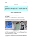
external device. The final setup should look like the setup in Figure 2.7.
Vincent A. Rosa
Florida Gulf Coast University
Spring 2009
Page 1 of 3
Atmel AVR STK500
Communicating with a
Host PC and Temperature Sensor
User Manual
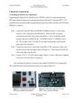
Figure 2.5 RXD and TXD pins of the RS232
SPARE port header.
Figure 2.6 RXD to PD0 and TXD to PD1 connection.
The green wire connects RXD and PD0 and the yellow
wire connects TXD and PD1.
Vincent A. Rosa
Florida Gulf Coast University
Spring 2009
Page 2 of 3
Atmel AVR STK500
Communicating with a
Host PC and Temperature Sensor
User Manual
Figure 2.7 Required setup for external RS-232 serial communication.
Vincent A. Rosa
Florida Gulf Coast University
Spring 2009
Page 3 of 3