1
AVR Freaks
By Sean Ellis
STK500 Getting Started
Introduction
Assumptions
A certain amount of knowledge is assumed, including the ability to launch programs, navigate the
Windows file system, to create folders, and to copy files from one folder to another. A basic
knowledge of PC hardware is also required, sufficient to connect a cable to a free serial ("COM:")
port.
Installing AVR Studio and AVR-GCC
This page gets us familiar with the STK500 package contents.
What's In The Box?
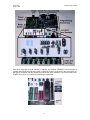
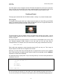
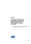
The first thing to do is to unpack the items from the box, onto a clean, flat work area.
As you open the box, on top is a list of the contents, which may differ slightly from those listed
here. For example, some distributors may include an additional sample microcontroller.
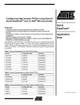
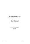
The STK500 Box and Contents
There should be a user guide booklet, which includes reference information about the board, as
well as its own Getting Started guide (Section 2). This set of web pages reiterates much of the
information in the Getting Started section, so you can use either this page or the User Guide to
get up and running, according to your own preference.
Under the paperwork is a CD-ROM which contains a snapshot of the Atmel website, including all
the information and data sheets for AVR microcontrollers and the AVR Studio software which you
will need later.
-1-
AVR Freaks
By Sean Ellis
STK500 Getting Started
Under this is the main board itself, in an anti-static bag. It is important to remember that modern
electronic devices can easily be damaged by static electricity, so try to ensure that you reduce
static whenever you are handling the board or the AVR chips that fit into it.
Note
It might be a good idea to purchase an anti-static wristband from your local electronic component
store as a means of reducing the possibility of static damage. These bands have a metal
conductor that makes contact to the user’s wrist. A wire connected to the conductor (usually with
an alligator clip on one end) allows you to connect the wristband with a power supply ground, or
computer case as a ground.
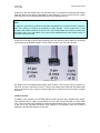
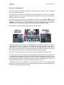
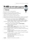
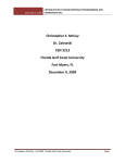
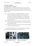
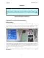
Along with the board are some bags containing grey and colored jumper cables for connecting
various parts of the STK500 together. These come in 10 pin, 6 pin, and 2 pin varieties.
The Different Cable Types
Not shown here is the supplied serial cable, which is about 1.5m long with a 9-pin connector on
each end, and is for connection to the PC. There is also a bare power cable with a suitable power
plug on one end, for use in case your power supply does not have the correct connector to power
the board.
Additional Items
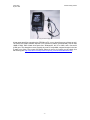
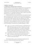
In addition to the contents of the STK500 starter kit itself, you will need a suitable power supply.
This should be able to supply at least 500mA at 10-15v DC, and be fitted with a 2.5mm power
plug. These are commonly available for powering small electrical items, and you should be able
to get one at any consumer electronics shop. Polarity is not important, since the STK500 is
designed to accept either polarity of connector.
-2-
AVR Freaks
By Sean Ellis
STK500 Getting Started
A Typical Power Supply
In later steps we will be connecting the STK500 to a PC, so you should have one of those as well.
The Atmel AVR Studio software requires a PC (Pentium or above recommended), with at least
16MB of RAM, 7MB of hard drive space free, Windows 95, 98, NT or 2000, and a free serial
(COM) port. This description covers virtually any new PC-compatible computer bought in the last
5 years or so. (Note: The current AVR Studio release is version 4.12 which you can obtain from
the following link: http://www.atmel.com/dyn/resources/prod_documents/aStudio4b460.exe)
-3-
AVR Freaks
By Sean Ellis
STK500 Getting Started
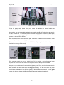
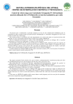
The Board Itself
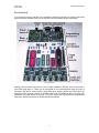
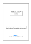
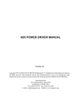
If you place the board so that the row of pushbutton switches is towards you, and the power and
serial connectors are away from you, we can take a look at the basic layout of the board.
The STK500 Board
Starting from the bottom, first there is a row of eight pushbutton switches, each of which has a
small LED lamp above it. These can be connected to the microcontrollers using the array of
connectors just above. There is then a large white area, which is where the AVR chips to be
programmed are inserted. Usually, a STK500 comes with a AT90S8515 (8515 for short) chip
mounted in the large socket on the right. The green area at the top contains the programming
electronics, and the connectors for power and communications.
-4-
AVR Freaks
By Sean Ellis
STK500 Getting Started
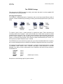
The STK500 Package
This page gets the STK500 powered up safely, and checks that both it and the supplied AVR
microcontroller are working correctly.
Checking Board Options
The STK500 is a sophisticated piece of equipment, and as such has several different modes of
operation. These are selected by connecting (or leaving unconnected) specific sets of pins on the
board.
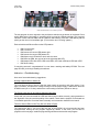
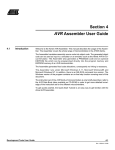
Jumper Positions
To connect a pair of pins, a small connector is pushed onto them. These connectors are
commonly referred to as "jumpers". A pair of pins is said to be "closed" when a jumper is pushed
on between them, and "open" if not. It is often common practice to push the jumper onto just one
pin for an "open" condition, so that it doesn't get lost. The picture above shows a typical two-pin
jumper in a closed and open position, and a three-pin jumper closed between pins 1 and 2, or 2
and 3 (three pin jumpers always have pin 1 marked).
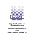
The STK500 should come with all its jumpers set up to select a sensible default set of options,
but it is worth checking that they are indeed in this default configuration before we go any further.
The jumpers are located at the top of the white area, on the left, and are labeled (from the outside
in) VTARGET, AREF, RESET, XTAL1, OSCSEL, and BSEL2. These should be in the state
indicated in the picture, and are also printed on the underside of the board for easy reference.
The defaults are:
VTARGET
RESET
XTAL1
OSCSEL
BSEL2
closed
closed
closed
closed
open
(between pins 1 and 2)
See picture on the following page for jumper locations.
-5-
AVR Freaks
By Sean Ellis
STK500 Getting Started
Default Jumper Positions
One other thing that is worth checking is that the pre-installed AT90S8515 microcontroller is
present and inserted the right way round. It should be a large, 40 pin chip in the large socket on
the right of the board, with the notched end toward the row of switches. If you have a brand new
STK500, then this is very unlikely to be missing or misaligned.
Correct 8515 Orientation
-6-
AVR Freaks
By Sean Ellis
STK500 Getting Started
Testing the STK500 Board
Before we connect the board to anything else, it is best to test it in isolation. This will verify that
the board is operating correctly.
The installed 8515 comes with a test program already programmed into it, which is very handy.
But before we can run it, we need to connect some of the outputs from the microcontroller to the
LEDs and switches on the board.
On the right hand side, just above the switches, is a group of 10 pins labeled "LEDS". These
need to be connected to the corresponding group of 10 pins just above and to the left labeled
"PORTB". In general, a group of pins arranged in this way and intended for a cable to plug into
them is known as a "header", so these are the LEDS header and the PORTB header.
On the left are two similar headers labeled PORTD and SWITCHES.
Close up of headers
One thing to notice is that each pin is individually labeled: on the LEDs header we have LED0 to
LED7, GND and VTG for the LEDs, and on PORTB we find PB0 to PB7, GND and VTG. It is
important that we connect the headers up in such a way that LED0 connects to PB0, LED1 to
PB1, and so on. Most particularly we must ensure that the two GND pins connect, and that the
two VTG pins connect, as these are the pins which carry the main power supply.
Similarly, to connect the switches we should connect SW0 to PB0, SW1 to PB1, and so on.
It is a good idea to do three things when connecting cables to headers: First, ensure power is off.
You might make a temporary connection due to a shaky hand, but that will not matter if there is
no power going into the board. Second, check that the cable is connected the right way round.
Third, check that the cable is connected the right way round once again. Whilst you may notice
that steps two and three are very similar, it really does not hurt to be sure!
To connect each set of two headers, use one of the short 10-pin to 10-pin jumper cables
supplied. To ensure that the cables are not twisted (which would connect the wrong pins), ensure
that the red stripe is on the left in both cases.
-7-
AVR Freaks
By Sean Ellis
STK500 Getting Started
Connecting the cables
I'll say this one more time: it's very important to ensure that cables are attached the right way
round, as putting them in the wrong way round can damage the STK500 and/or the
microcontroller inserted into it.
As an aside, you may be wondering why we're connecting ports B and D, when there are ports A,
C and E available too. The overriding reason is that the test program is written to use these ports,
which is because they are physically the easiest ones to connect on the board. They are also
present on almost all AVR devices.
With the switches and LEDs connected (did I mention to double check the orientation of the
connecting cables?), we are ready to power on.
First, ensure that the power switch on the STK500 is off (the toggle should be in the position
farthest from the edge of the board).
Power switch and connections
Plug you power supply into the wall, switch it on (if it has a switch - most wall-mounted power
supplies like mine do not), and connect it to the power socket at the top left of the board.
Are you sure your cables are all connected the right way round? If so, switch on the power switch.
With the switch on, three small LEDs should light immediately. The red one next to the power
switch indicates that power is available to the STK500 itself. The green one at the top left of the
central white area indicates that power is getting to the installed microcontroller, and the green
one on the right near the top indicates that the programming hardware is ready to go.
-8-
AVR Freaks
By Sean Ellis
STK500 Getting Started
LEDs should blink when switch SW0 is pressed
The test program is set to respond to the push button switches at the bottom of the board. Press
switch SW0 (at the right) briefly. If everything is OK, most of the LEDs should light. This is a good
indication. Press and hold SW0 and the LEDs will start flashing, with each LED flashing half as
quickly as the one on its immediate right. (This is known as a "counting" pattern.)
Each switch has a different effect on the LED patterns:
•
•
•
•
•
•
•
•
SW0 "counts down".
SW1 "counts up".
SW2 moves the current LED pattern right.
SW3 moves the current LED pattern left.
SW4 lights every LED which is dark, and vice versa.
SW5 same as SW4, but only as far as the rightmost dark LED.
SW6 swaps LED0 with LED4, LED1 with LED5, LED2 with LED6 and LED3 with LED7.
SW7 does nothing
If everything went well, congratulations! You now have a working and healthy STK500. The next
page will take you through installing the software.
Otherwise... (Troubleshooting)
Here are a few troubleshooting suggestions.
Nothing Happens When I Switch On
The most obvious thing to check is that the power supply is turned on and giving power. If you
have a voltmeter, check that the voltage coming out of the power supply is sufficient to drive the
STK500 board (10 to 15 volts), and that the current rating is sufficient (500mA or above).
The Power Lights Are On but Nothing Happens Otherwise
Check that you have connected the LED and Switch jumper cables correctly, paying attention to
the alignment of the pins and the polarity of the cables. Check that the jumpers on the board are
in the default positions. Check that there is actually a microcontroller installed in the board!
There Are Some LEDs On But They Don't Do What I Expect
The chances are that, if you are not the first user of the STK500, the microcontroller has been
reprogrammed, erasing the test program supplied by default. In this case, you will have to
progress to the next page, install the programming software and reload the test program.
-9-
AVR Freaks
By Sean Ellis
STK500 Getting Started
Setting Up The STK500
AVR Studio is a free suite of Windows software from Atmel that enables you to create, edit, and
assemble programs for the AVR microcontrollers, and then transfer them to real AVR chips
installed in the STK500 board and run them.
This page gets us ready to install the AVR Studio software. It is assumed that you have set up
and checked your STK500 evaluation board as outlined in the previous pages.
Requirements
The Atmel AVR Studio software requires a PC (Pentium or above recommended), with at least
16MB of RAM, 7MB of hard drive space free, Windows 95, 98, NT or 2000, and a free serial
(COM) port. This description covers virtually any new computer bought in the last 5 years or so.
In order to read or print the user manual, you will also need appropriate Adobe Acrobat viewer
software. This is distributed on the Atmel CD that came with the STK500, so assuming that your
CD-ROM drive is drive D:, you can install it by running the file D:\adobe\windows\ar40eng.exe
(that cryptic filename is short for "Acrobat Reader 4.0 English").
This version of the software should work fine with the user manual. However, if you don't have
access to the Atmel CD, the latest version of the Acrobat reader is available for free download
from Adobe themselves at their Acrobat Reader download page. The current version at time of
writing is about 8.6 megabytes, or just under an hour's download on a typical modem connection.
Obtaining AVR Studio
Atmel are continuously upgrading AVR Studio, so it is a good idea to work with the latest version.
Although there is a version of AVR Studio included on the Atmel CD that comes with the STK500,
it is best to take the time to download the latest version either from Atmel's website or here on
AVRFreaks.net.
On AVRFreaks.net, the latest version is available in the Tools section of the site. I am not going
to link directly to the downloads, since the download page for AVR Studio always contains links to
the very latest version. You can also find this page by selecting the Tools tab, then selecting
Assembler from the left hand list of tool categories, then selecting AVR Studio from the resulting
list of links.
To begin with, you will want to download two files from the Tools page - the AVR Studio Install
File (astudio3.exe 1 ), and the AVR Studio 3 User Guide (doc1019.pdf 2 ).
The AVR Studio install file is about 6 megabytes in size, which translates as about 30 minutes
download time on a typical dialup connection. To download, just click on the link and choose
"Save to disk" when prompted. You only need this file on disk temporarily, so choose a temporary
folder such as C:\Temp to save it into.
You will also need to download the user guide. This is much smaller, about 173 kilobytes, well
under 2 minutes' download time. This you will need to save somewhere more permanent. I
suggest that you navigate to your "My Documents" folder, and make a new folder under that
called "AVR", and save the user guide in there.
1
2
This filename maybe different for later versions of the AVR Studio (aStudio4b460.exe for 4.12)
This filename maybe different for later versions of the User’s Guide
- 10 -
AVR Freaks
By Sean Ellis
STK500 Getting Started
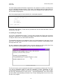
Installing AVR Studio
This page installs the AVR Studio software.
The Installation Process
Find the install file you saved to disk in the previous step, and run it by double-clicking on it. This
starts the install process. (The process itself is quite quick, and actually takes less time to do than
it does to read this guide!)
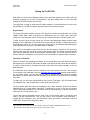
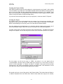
Unzipping the files
The first stage of the install unpacks all the files from the installer to a temporary location. The
dialog box that appears suggests a temporary folder to use during this process, but we'll need to
find this folder later so it is easier just to type C:\Temp as the folder to use. Once this is done,
click on the Unzip button to continue.
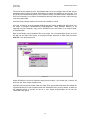
Assuming everything went well, a small message box appears, reporting the successful
unpacking of the files to C:\Temp. Click on the OK button to continue. This takes us back at the
unpacking dialog. Click on the Close button to finish this part of the installation.
This has unpacked all the files we need to install into a new folder under C:\Temp, called
"cdrom". (Presumably because this installation is also destined for future versions of the Atmel
CD.) Select the "cdrom" folder and double-click on the SETUP.EXE program in order to run it.
- 11 -
AVR Freaks
By Sean Ellis
STK500 Getting Started
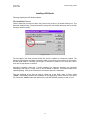
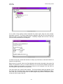
Installation splash screen
You will be presented with the installer's introduction screen. This advises you to close all other
Windows programs before continuing with the installation, and so this is definitely a good idea.
Once the installer is the only thing running, click on the Next button.
The next step is the lawyer's favorite dialog box - the one that contains the software license. I am
not a lawyer, and so cannot advise you on whether this license suits you or not, but the bottom
line is that if you don't click the Yes button to accept the terms of the license, you don't get to play
with the software. Let's assume you click "Yes" and carry on to the next screen...
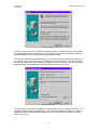
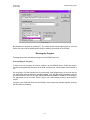
Choose destination folder
The next dialog in the sequence suggests a default folder in which to install AVR Studio. The
suggestion seems like the right place to put it to me, but if you disagree you have the chance to
change the folder by clicking on the Browse button. Once you are happy, click Next to continue.
(We’re nearly there!)
- 12 -
AVR Freaks
By Sean Ellis
STK500 Getting Started
The next screen asks for the name of the folder which will appear in the start menu. You have the
chance to edit this name if you don't like the default. Once you are happy, click Next.
At this point, the actual installation of the files into their final locations takes place, which may take
a few seconds.
The final screen asks for permission to restart the machine. In general, I am very forgetful, so I
always give my permission to restart immediately. Otherwise, I run the risk of forgetting to do so
and getting problems because of it. If you choose the Restart Now option, clicking Finish will
restart your computer and finish the installation. If you choose the Restart Later option, clicking
Finish will mean that the final finishing touches to the installation will only happen next time you
restart, so you will have to restart manually before proceeding to the next step.
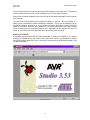
Running AVR Studio
If everything has gone well with the install (remember to restart the computer if you haven't
already), you should have a new folder in your Start menu, which if you accepted the default
name will be called "Atmel AVR Tools". Inside this is a shortcut to the AVR Studio program. Click
it to start AVR Studio.
AVR Studio Running
- 13 -
AVR Freaks
By Sean Ellis
STK500 Getting Started
The initial splash screen will appear and the AVR Studio development environment is presented.
This is a bit bare to start with since we haven't created anything yet. Almost all the icons in the
toolbars are greyed out, since they have no effect until we load or create a project to edit.
Creating a Project
This page gets us started with the AVR Studio software, creating a very simple example project.
The Program
The simplest AVR program which has a visible output just lights one of the LEDs on the STK500
board. The example program here lights LED0, the rightmost in the row of eight LEDs above the
pushbuttons on the near end of the board, and then halts.
A close-up of LED0
The actual detail of how the program works is not particularly relevant at this stage - like the
program already loaded into the AVR in a new STK500, it is used to demonstrate the process of
creating a program.
We cannot easily write the program directly in a form which is downloadable onto the chip. Why
not? Because programs written directly for the chip itself are the next best thing to
incomprehensible. For example, here is the actual code we are going to download onto the chip.
B89A C098 FFCF
Each 4-digit code represents a single instruction that the AVR can carry out. This is easy for
simple computers to deal with, but a nightmare for humans.
Obviously, we need a better way of dealing with this. A program which converts a more readable
form of each instruction into these numeric codes is known as an assembler, and the ‘AVRAsm’
assembler is included with AVRStudio.
Our assembler listing is pretty small - only 5 lines long and only 3 of those actually translate into
instructions. Here it is:
.include "8515def.inc"
.org 0
sbi DDRB,0
cbi PORTB,0
halt: rjmp halt
We will go through this program in more detail in the basic assembly language tutorial later on.
For now, we can treat it as a "black box" that stands in place of any assembly language program.
- 14 -
AVR Freaks
By Sean Ellis
STK500 Getting Started
Creating the Projects Folder
AVR Studio organizes all the files and settings for a single program as a "project", which resides
in its own folder on your hard drive. AVR Studio itself will create a new folder for each project, but
will not create the folder that the project folders themselves are stored in. (For example, if you
want to put your project in C:\Projects\LED0, then AVR Studio will quite happily create the LED0
folder, but only if the folder C:\Projects already exists.)
If you do not have an existing folder to put all your projects in, create one called "C:\Projects".
Creating the Project
Our ultimate goal is to type the program into the computer, feed it through the assembler, and
download it to the chip on the STK500. To do this, we will create a new project in AVR Studio.
With the housekeeping out of the way, now we can start the AVR Studio software.
Once the splash screen has disappeared, you should be left with a blank work area and a set of
menus and toolbars along the top, much as you would expect from a Windows application.
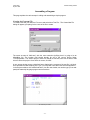
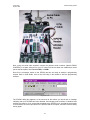
To create a new project, pull down the Projects menu and select New... The Select New Project
dialog box will appear. It is here that we get to set some of the most basic options for our project.
The Select New Project dialog box
For this project, we will set its name to "LED0", and where it is to be stored will be
"C:\projects\led0". We also need to indicate what type of project it is. In this case, we have a
choice of "AVR Assembler" or "Generic 3rd Party C Compiler". Since this and all the other
projects later in this series, are assembler projects, we should select "AVR Assembler" for this
one. When all is correct, click OK and the project will be created.
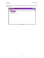
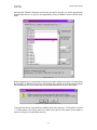
We should now have a view of the project in the Project window. This window has two folders in
it, labeled "Assembler files" and "Other files". Both of these folders are empty at the moment,
- 15 -
AVR Freaks
By Sean Ellis
STK500 Getting Started
because we haven't actually created any files to go into them yet - this is just a view onto the
project folder.
The Project window
- 16 -
AVR Freaks
By Sean Ellis
STK500 Getting Started
Assembling a Program
This page explains the various steps in editing and assembling a simple program.
Creating the Program File
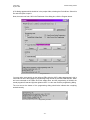
To create a new file, pull down the File menu and select New Text File... The Create New File
dialog will appear, prompting for the name of the file to create.
The Create New File dialog box
The name we want is "led0.asm", with the .asm extension signifying that it is going to be an
ASseMbler file. The location field should already be set to the current project folder,
"C:\Projects\led0". The "Add to project" check box should be checked, since we do want to add
this new file to the project. Once all this is correct, click OK.
A new, empty window opens, entitled led0.asm, displaying the contents of the new file. It is blank,
since we haven't written anything into it yet. (You may also notice that a new item has appeared
in the Projects window, also entitled led0.asm.) Into the new window, we need to type (or cut-andpaste) the assembly language program we wrote above.
The led0.asm file window
- 17 -
AVR Freaks
By Sean Ellis
STK500 Getting Started
The editor software within AVR Studio recognizes the .asm extension on the file, and realizes that
this is an assembly language program. In this case, it will highlight particular things within the
program using different colors. This is perfectly normal and is designed to give additional cues to
the user while writing programs.
Here is the program again (in black and white) for cut-and-paste purposes:
.include "8515def.inc"
.org 0
sbi DDRB,0
cbi PORTB,0
halt: rjmp halt
Always save work regularly. To save the file, pull down the File menu and select Save. This will
save the file to the disk.
Assembling the Program
Let us now try assembling the program. To do this, either pull down the Project menu and select
Assemble, or press key F7. This submits the program we just wrote to the assembler, which tries
to interpret it and convert it to raw machine instructions.
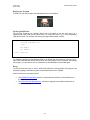
The assembler itself opens a new window to inform you of what happened. In this case, it is not
good news. The assembly process failed. The last line shows a summary of what happened, and
as it says there was 1 error.
So, am I presenting a faulty program? Have I just been stringing you along all this time? Not
quite. We will have to read through the rest of the output to understand why.
The Project Output window
The first two lines are just the copyright information for the assembler software itself. Then there
is a line of information telling us what the assembler is doing, assembling our file,
c:\projects\led0\led0.asm. However, the next line is the informative one. Again, it tells us which
file was being assembled when it found the error - c:\projects\led0\led0.asm, and it also includes
the line number it was assembling in brackets. Here, it is (1), indicating that the error is in the very
first line of our program.
- 18 -
AVR Freaks
By Sean Ellis
STK500 Getting Started
The rest of the line details the error, and indicates that it is not our program that is at fault, but the
assembler cannot find the file called "8515def.inc" file which was specified on the first line. This
file (as well as corresponding files for all the different AVRs) is included with the assembler, but
since it's not actually in our project, the assembler does not know where to find it. We must copy
it into our project folder.
Close the Project Output window, since it won't be needed for a while.
All of the .inc files for all of the possible AVR devices are initially installed with AVR Studio, into
the folder “C:\Program Files\Atmel\AVR Studio\Appnotes”. Using Windows Explorer, or by
exploring from My Computer, copy the file 8515def.inc from this folder to our project folder,
C:\Projects\LED0.
Back in AVR Studio, we must add this file to our project. It's not an assembler file per se so we
will add it to the "Other Files" group. In the project window, right-click on Other Files and select
Add File... from the pop-up menu.
Adding a file
Select 8515def.inc from the file selection dialog and click Open. If you cannot see it, choose "All
files" from the "Files of type" dropdown first.
8515def.inc should now be visible under the "Other Files" group. Notice that when we created the
original led0.asm file, it was not placed under the "Assembler Files" group by default, so while we
are assigning things to groups we can do it now. Simply drag-and-drop the file into the
"Assembler Files" group.
- 19 -
AVR Freaks
By Sean Ellis
STK500 Getting Started
Drag and drop led0.asm
Let us check if this actually worked. Assemble the project again using the menu (Project,
Assemble) or press F7. The Project Output window reappears, and with a bit of luck this time the
bottom line has a very happy message indeed - "Assembly complete with no errors". We have
just successfully assembled our first program.
Assembly successful
(If it does not say this, recheck that led0.asm is exactly as printed above, and that 8515def.inc is
indeed in the right folder.)
Before we can run the file, there is one final adjustment that needs to be made to the project. By
default, the assembler is set up to output instructions in a form that AVR Studio's built-in AVR
simulator software can deal with. If, as we do, we want to run the program on a real AVR, we
must change the output format for the assembler.
From the Project menu, select Project Settings... The Project Settings dialog box appears. From
the Output File Format drop-down, select the option labeled "Intel Intellec 8/MDS (Intel HEX)".
This is the name of the file format that the STK500 programming software understands (known
for short as "hex" format). Click OK.
- 20 -
AVR Freaks
By Sean Ellis
STK500 Getting Started
Project settings
Re-assemble the program by pressing F7. The output window should appear with no errors as
before. We now have an assembled file ready for transfer into the AVR on the STK500.
Running the Program
This page shows how to download a program to the STK500 and run it.
Downloading the Program
In order to run the program, we need to transfer it to the STK500, and to do that we need to
connect the programming electronics to the AVR on board. First, ensure power to the STK500 is
off.
We are going to use the simplest form of programming, serial programming, so we must connect
the appropriate serial programming headers together. First, find the two 6 pin headers near the
rear end of the 8515 chip, on the right, labeled ISP6PIN and SPROG3. SPROG3 is connected to
the appropriate pins on the 8515, which is why it has a red background and so does the 8515
socket.
Using the 6 pin cable that came with the STK500, connect these two headers together, ensuring
that the cable is not twisted.
- 21 -
AVR Freaks
By Sean Ellis
STK500 Getting Started
Connections for downloading
Next, using the serial cable supplied, connect the leftmost serial connector (labeled RS232
CONTROL) to a spare serial port on your PC. Most PCs have at least one suitable 9-pin serial
port on the back panel, often labeled COM1: or COM2:.
Once this is connected, switch on the STK500 and we are ready to attempt a programming
session. Back in AVR Studio, click on the AVR chip on the toolbar to start the programming
software.
Programmer icon
The STK500 dialog box appears. In the text area at the bottom you should see a message
indicating that your STK500 has been detected, and showing what revisions of hardware and
software are present. If not, ensure that the power to the STK500 is on, and that the serial cable
is connected to the correct port both on the STK500 and the computer, and then close the dialog
and try again.
- 22 -
AVR Freaks
By Sean Ellis
STK500 Getting Started
Assuming the STK500 is detected, the first thing we need to do here is to tell the programming
software what device it is going to be programming. Select AT90S8515 from the Device dropdown.
Choose your device
Before programming, it is a good idea to erase any program already in the device. Click the Erase
Device button. If everything is OK, then the text area at the bottom of the dialog should indicate
that everything is OK. If not, dismiss any error dialogs and double-check your wiring again.
Communications problem? Double-check wiring.
To program the device, we must tell the software which file to send to it. To find the file, click the
"..." browse button in the "Flash" area, to the right of the "Input Hex File" space. (The program is
stored on the chip in so-called flash memory.)
- 23 -
AVR Freaks
By Sean Ellis
STK500 Getting Started
A file dialog appears which should be in the project folder, showing the file led0.hex. Select this
file and click Open to open it.
Now, the moment of truth. Still in the Flash area of the dialog box, click the Program button.
Program the device
You may notice some activity on the leftmost LEDs while the AVR is being programmed - this is
normal and is due to the signals for programming being carried on pins PB5, PB6 and PB7, which
we have connected to the LEDs. Once this settles down, and the programming is finished, the
actual program will start and light the rightmost LED. You can now close the programming dialog.
The text area at the bottom of the programming dialog should also indicate that everything
worked correctly.
Programming succeeded
- 24 -
AVR Freaks
By Sean Ellis
STK500 Getting Started
Running the Program
If LED0 is lit, then the program was downloaded and run successfully.
The light of achievement
Further Qualification
The two lines containing the constant value 0 can be changed, to use any value from 0 to 7
(although both lines must use the same value). For each value from 0 to 7, the corresponding
LED will then be lit. For example, the following will light LED4 instead of LED0:
.include "8515def.inc"
.org 0
sbi DDRB,4
cbi PORTB,4
halt: rjmp halt
Try editing the program to light different LEDs, to get familiar with the sequence of events. (To reopen a file which has been closed, double-click on it in the project view.) A reminder: after editing
the program, you will need to save it, re-assemble it, and download it to the board again.
Recap
You should now know how to use the AVR Studio software to create simple AVR projects, edit
assembly language, assemble programs, and download them to the STK500.
Useful resources for next steps include:
•
•
The AT90S8515 data sheet, which is a comprehensive reference to the architecture of
the 8515.
The AVR Instruction Set Reference, which as it suggests is the definitive reference for
assembly language.
- 25 -