1
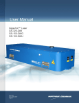
LaserFlash Plus
Manual
User Manual
September 2006
OptoPrecision GmbH, Auf der Höhe 15, D-28357 Bremen, Germany
Tel: +49(0)421 94961-10 Fax: +49(0)421 94961 -99,
Internet: www.Optoprecision.de
1 / 10
Table of Contents
1. Juridical Information....................................................................................................................... 3
1.1. Copyright .............................................................................................................................. 3
1.2. Trademark.............................................................................................................................. 3
1.3. Warranty ................................................................................................................................ 3
2. Safety Instructions..........................................................................................................................3
3. Laser Class.................................................................................................................................... 4
4. The System.................................................................................................................................... 4
5. Operating Principle.........................................................................................................................4
6. Interface ........................................................................................................................................ 5
6.1. Power Supply .........................................................................................................................5
6.2. Trigger Input........................................................................................................................... 5
6.3. RS 232 Interface.....................................................................................................................5
6.4. Potentiometer (optional) ........................................................................................................ 5
7. Aperture Angle of Front Frame...................................................................................................... 6
7.1. Change of Front Frame.......................................................................................................... 6
8. Short Instruction............................................................................................................................. 7
8.1. Operation with TrigBox 3.0..................................................................................................... 7
8.2. Operation with own Pulse Transmitter................................................................................... 7
8.3. Operation with fixed Pulse Adjustment per Potentiometer(optional).....................................7
9. Dimensions.....................................................................................................................................8
10.Technical Specifications................................................................................................................9
11. Attachments................................................................................................................................. 9
User Manual
September 2006
OptoPrecision GmbH, Auf der Höhe 15, D-28357 Bremen, Germany
Tel: +49(0)421 94961-10 Fax: +49(0)421 94961 -99,
Internet: www.Optoprecision.de
2 / 10
1. Juridical Information
1.1. Copyright
This manual is copyrighted and is not allowed to be copied, reproduced or modified, complete or
partly, without written confirmation by OptoPrecision. There is an exception made for backups for
personal usage. Passing on this manual and the information it contains, is only allowed with
written confirmation by OptoPrecision.
1.2. Trademark
All trademarks are the property of each particular company.
1.3. Warranty
This manual has been written with utmost accuracy and was checked according to correctness
due to the state of the art. OptoPrecision is only liable in case of intention or gross negligence for
direct or indirect damages in connection with the manual as well as casual or consequential
damages. For loss or damage of data due to direct or indirect mistakes as well as for costs which
can be traced back to the manual or to installations which were not made by OptoPrecision, all
liability claims are explicitly excluded. The information in this manual can be changed due to
technical progress without extra notice.
2. Safety Instructions
Before installing the LaserFlash Plus please study the manual carefully!
•
The laser class of the device is mentioned in the inspection sheet. Furthermore there is a
mark at the device due to Lasernorm DIN EN 60825-1.
•
Is the device marked with laser class 1, there is no danger for human eyes or skin.
•
Is the device marked with laser class 3R, please make arrangements due to laser norm
DIN EN 60825-1. While the device is operating, please wear safety goggles and avoid to
look into the beam. Attention: Danger of irreversible damage of eyes.
•
For changing the front lenses (lenticular lenses in the front frame) please take notice of the
safety instructions mentioned in this manual.
•
Attention: Please never operate the device without properly fitted lenticular lenses. There
is danger of irreversible damage of eyes.
•
While changing the front lenses an interlock is switched, which prevents that the
LaserFlash emitts light. Attention: Bridging of the interlock pins can lead to burnings and
irreversible damages of eyes through laser radiation.
•
Within the device there are no parts which can be repaired or maintained by the operator.
Maintenance and repair work can only be done by qualified personnel.
•
Within the device dangerous radiation is generated. The device is not allowed to be
opened by other than authorised personnel with knowledge of laser norm DIN EN 608251.
•
In operation the casing can heat up to 60°C. The fitting cooling fan for LaserFlash Plus is
IP55.
•
The device is operated standardly with 12V (see specifications). If required, higher voltages
are deliverable.
User Manual
September 2006
OptoPrecision GmbH, Auf der Höhe 15, D-28357 Bremen, Germany
Tel: +49(0)421 94961-10 Fax: +49(0)421 94961 -99,
Internet: www.Optoprecision.de
3 / 10
3. Laser Class
The device is classified in laser classes due to DIN EN 60825-1. The compliance with laser
classes is guaranteed by the device´s hardware, so that the stated laser class can not be
exceeded. The laser class ist marked on the device. All power data, permissions and certifications
are mentioned in the attachment and the inspection sheet.
4. The System
The LaserFlash Plus is a light source based on a laser diode. It is used for illumination purposes. If
an appropriate signal is applied to the trigger input, the LaserFlash Plus emits light pulses in the
near infrared spectral region. The light pulse length is as long as the electrical input pulse, only
limited if the laser norm is exceeded. The pulses have a defined maximum intensity, defined beam
angles and a fixed maximum duty cycle.
The system is designed for applications, where high intensities of light are required. The detection
or documentation of car registration numbers in the case of tolling may be an example for an
application. For diverse applications very effective systems can be created by adequate
combinations of camera, TrigBox and LaserFlash Plus. The LaserFlash Plus is superior to other
light sources, such as LED or Xe-Flash, when the application is characterized by longer working
distances or a higher energy demand, or typical laser attributes such as spectral characteristic,
polarization or free design of the pulse shape are required. The spectral emission is alternatively
785nm, 808nm or 940nm.
5. Operating Principle
The laser radiation is emitted through a rectangular beam window. On the rear of the LaserFlash
Plus, there are several electrical connectors, LEDs and actuators. The laser radiation is generated
by a QCW laser diode (LD), implemented in the LaserFlash Plus. An electronic circuit provides
current pulses of maximum 150A to drive the LD. The duration of the light pulse corresponds to
that of the trigger signal. However, internal circuits restrict pulse height, length and repetition rate
in a way that save operation is given (here laser class 3R!) and that degradation of the LD is
avoided. In order to guarantee a long life time for the LD, its internal temperature is held by 25 °C.
The produced waste heat is emitted to the ambient air. Water cooling is not necessary. The
LaserFlash Plus has an external cooling fan (IP55).
The LaserFlash Plus is protected against overheating. Over-temperature can occur at high dutycycles together with high ambient temperature. If, due to over-temperature, the LD-temperature
rises above 25°C, flashing is stopped by an internal protection circuit. The LaserFlash Plus restarts flashing, as soon as the unit is able to cool the LD down to 25°C, again. To run the
LaserFlash Plus at maximum duty-cycle, please take care to keep the temperature of the case
below 45°C. Attention, in operation, the casing can heat up to 60°C!
The LaserFlash is equipped with an internal heating. If the device is operated at temperatures
below 20°C, the device heats automatically up to an operating temperature of 20°C. Only then
light pulses can be emitted. At low temperatures this can last up to 40 minutes. If the ambient
temperature exceeds 20°C, the device automatically keeps the optimal operating temperature.
User Manual
September 2006
OptoPrecision GmbH, Auf der Höhe 15, D-28357 Bremen, Germany
Tel: +49(0)421 94961-10 Fax: +49(0)421 94961 -99,
Internet: www.Optoprecision.de
4 / 10
6. Interface
(2)
(3)
(6)
(4)
(1)
(5)
#
Assignment
Comments
1
Power Supply
12 V nominal
2
Trigger Input
TTL Trigger Input (max 12 V signals)
3
RS232 Interface
Communication with PC (readout and modification)
4
LED Green
Flashes when a pulse is emitted
5
LED Red
Flashes in operation
6
Potentiometer (optional)
Adjustment of pulse length from 100 µs-2 ms
6.1. Power Supply
The supply voltage is applied via the fixed cable. The pin plug is fixed via the storage battery or the
power supply unit. The nominal working voltage amounts to 12 V (see specifications). The power
input is dependent on the kind of application and can vary from 1 A to 15 A (see test report).
User Manual
September 2006
OptoPrecision GmbH, Auf der Höhe 15, D-28357 Bremen, Germany
Tel: +49(0)421 94961-10 Fax: +49(0)421 94961 -99,
Internet: www.Optoprecision.de
5 / 10
6.2. Trigger Input
The light pulse is generated by applying a voltage (12V) to the BNC-pulse input. The duration of
the light pulse corresponds to the length of the applied electrical pulse, up to the adjusted
maximum pulse length.
Trigger Input and RS232 Interface
6.3. RS 232 Interface
The LaserFlash Plus can optionally be connected via RS232 cable to a PC. Relevant parameters
can be modified at the interfaces in several password levels.
Attention! : Through incorrect parameters the LaserFlash can become dangerous to human eyes
(laser class 3R and 4). Furthermore, incorrect parameters can cause overstress for the LaserFlash
and hence, destroy the laser diode.
6.4. Potentiometer (optional)
Optional, the device can be equipped with a potentiometer in order to adjust a fixed pulse length.
This is independent of the input pulse and triggers to the positive side. The pulse length can be
varied from 100µs to 2ms.
User Manual
September 2006
OptoPrecision GmbH, Auf der Höhe 15, D-28357 Bremen, Germany
Tel: +49(0)421 94961-10 Fax: +49(0)421 94961 -99,
Internet: www.Optoprecision.de
6 / 10
7. Aperture Angle of Front Frame
In the front frame there are mounted two lenses which define the cone of light´s aperture angle
horizontally and vertically. The aperture angle can easily be adapted to different applications by
changing the front frame.
7.1. Change of Front Frame
The front frame can easily be changed.
Attention: Please take care of the surface inside the front frame. The back of the lenticular lenses
is antireflective coated (microstructure). Please do not try to clean or wipe. This may destroy the
microstructure and hence, cause a loss of light.
Twist off the two screws.
Lift the front frame constantly, the Interlock Pins
may need a little force to come off.
The Interlock Pins act as guidance for fixing the Press the front frame on the LaserFlash and
new front frame.
fasten it with two screws. The two Interlock
switches will click when the assembly is
accurate.
User Manual
September 2006
OptoPrecision GmbH, Auf der Höhe 15, D-28357 Bremen, Germany
Tel: +49(0)421 94961-10 Fax: +49(0)421 94961 -99,
Internet: www.Optoprecision.de
7 / 10
8. Short Instruction
8.1. Operation with TrigBox 3.0
•
If the device is not conform to laser class 1, please make arrangements for radiation
protection by wearing safety goggles.
•
The LaserFlash has to be connected to power supply 12V,8A. The red LED begins to
flash.
•
The TrigBox has to be connected to the power supply unit. The red LED at the TrigBox
flashes.
•
The TrigBox (trigger output) has to be connected to the LaserFlash per BNC-cable .
•
Please apply the camera´s analog signal to the TrigBox Input. The green LED at the
TrigBox flashes when an adequate signal (FBAS) is received.
•
Simultanously the green LED at the LaserFlash flashes, thus confirming that a pulse is
applied and that light pulses are emitted. Pulse length and pulse deceleration can be
adjusted by means of the Trig Box.
8.2. Operation with own Pulse Generator
•
If the device is not conform to laser class 1, please make arrangements for radiation
protection by wearing safety goggles.
•
The LaserFlash has to be connected to power supply 12V,8A. The red LED begins to
flash.
•
The pulse transmitter has to be connected with the LaserFlash. The applied pulse length
corresponds to the pulse length of the light pulse.
•
The green LED at the LaserFlash confirms that a pulse is applied and that light pulses are
emitted.
8.3. Operation with fixed Pulse Adjustment per Potentiometer(optional)
•
If the device is not conform to laser class 1, please make arrangements for radiation
protection by wearing safety goggles.
•
The LaserFlash has to be connected to power supply 12V,8A. The red LED begins to
flash.
•
The pulse transmitter has to be connected with the LaserFlash. The pulse length of the
light pulses can be adjusted by means of the potentiometer.
•
The green LED at the LaserFlash confirms that a pulse is applied and that light pulses are
emitted.
User Manual
September 2006
OptoPrecision GmbH, Auf der Höhe 15, D-28357 Bremen, Germany
Tel: +49(0)421 94961-10 Fax: +49(0)421 94961 -99,
Internet: www.Optoprecision.de
8 / 10
9. Dimensions
User Manual
September 2006
OptoPrecision GmbH, Auf der Höhe 15, D-28357 Bremen, Germany
Tel: +49(0)421 94961-10 Fax: +49(0)421 94961 -99,
Internet: www.Optoprecision.de
9 / 10
10.Technical Specifications
Emission Wavelength
Pulse Width Minimum
Pulse Width Maximum
(selectable)
Maximum Frequency
Aperture
Field Angle
Power Supply
Power Consumption
Max.
Operating Temperature
Storing Temperature
Relative Humidity
Cooling
Weight
Dimensions
Laser Classification
Pulse Input (BNC)
PC Communication
Unit
nm
.µs
.ms
Hz
mm
H/V
V
W
°C
°C
%
kg
mm
V
LaserFlash Plus
Type
785nm, 808nm 940nm
15
1
15
150 x 170
3° to 23° (see Attachment)
10-14
100
10°C-50°C
0°C-50°C
80
fan forced cooling
5
170x210x240
1 / 3R (see Test record, see LaserNorm DIN EN
60825-1)
3V-15V Pulses
RS232 115200Baud
11. Attachments
•
Included in delivery: LaserFlash Plus, cable power supply, manual, inspection sheet (see
delivery note)
User Manual
September 2006
OptoPrecision GmbH, Auf der Höhe 15, D-28357 Bremen, Germany
Tel: +49(0)421 94961-10 Fax: +49(0)421 94961 -99,
Internet: www.Optoprecision.de
10 / 10