1
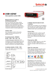
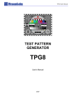
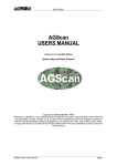
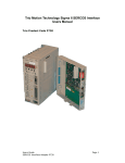
Gain Controlled Pre Amplifier
Installation
Version 1.0
1st November 2006
CONTENTS
USB Gain Controlled Pre Amplifier....................................................................................................3
Installation............................................................................................................................................5
Hardware Installation.......................................................................................................................5
Front Connections ........................................................................................................................5
Recommended connections......................................................................................................5
Rear Connections .........................................................................................................................7
USB..........................................................................................................................................7
I/O ............................................................................................................................................7
DC ............................................................................................................................................7
ON-OFF ...................................................................................................................................7
Out 1.........................................................................................................................................8
Out 2.........................................................................................................................................8
Out 1 & 2 .................................................................................................................................8
Recommended output connections ..........................................................................................8
Software Installation ........................................................................................................................9
Installation of drivers ...................................................................................................................9
Activating of Preamplifier ...........................................................................................................9
P830 functions .........................................................................................................................9
I/O Connections .................................................................................................................................11
Input Pins .......................................................................................................................................11
Output Pins.....................................................................................................................................11
Timing diagram for P830 & P730 I/O signals ...............................................................................12
P830 & P730 I/O pin out ...............................................................................................................12
Input ...........................................................................................................................................12
Outputs .......................................................................................................................................12
I/O = Normal (or not defined)................................................................................................13
I/O = Separate ........................................................................................................................13
I/O = Group............................................................................................................................13
The Alt4-hw.cfg file...................................................................................................................14
USB Gain Controlled Pre Amplifier
The Gain Controlled Pre Amplifier (GCA) is a preamplifier designed to use with P730 Picro Pro+
and P830+ acoustic test systems.
One GCA can be added to the P730 test system mean wile up to 4 GCA’s can be added to a P830
test system.
A GCA has two balanced inputs supplied with a combo XLR / Jack plug. The XLR connection can
freely be supplied with a phantom voltage +48 V. The voltage is selected for each input on the
backplane.
For easy calibration of the P730 and P830 test systems the GCA has a reference generator. This
enables an automatically test and calibration when the p730 and p830 program enter the run and
setup modes.
For external control as signals as test results and start test the GCA have a digital input and out lines
at TTL level.
DC/DC
+48 V
USB
REF
I/O
DB 25
In 1
XLR /
JACK
Out 1
RCA
Out 1 & 2
JACJK
In 2
XLR /
JACK
Out 2
JACK
Block Diagram
Installation
Hardware Installation
Front Connections
2
1
3
Input 2
Input 1
Front view
On front are placed the two combo plugs for input 1 & 2. The combo plug support the XLR and
Jack style.
The XLR inputs support a +48 V phantom supply for microphones. This voltage is selected on the
backplane for each input.
Recommended connections
Balanced input – XLR & Jack
Source
Signal −
Signal +
GND
XLR Input
3
2
1
Source
Jack Input
Signal −
Mid-ring
Signal +
GND
Tip
Screen
Single-ended input
Source
Signal +
GND
XLR Input
3
2
1
Source
Jack Input
Signal +
GND
Mid Ring
Tip
Screen
Rear Connections
USB
I/O
1
ON -OFF
DC
2
ON-OFF
+48 V
Out 1
Out 2
Out 1 & 2
Rear View
USB
USB connection to PC.
The GCA get normally the power via this connection.
I/O
The I/O is digital input and output port. There are 8 inputs and 8 outputs ports all at TTL level.
A DB-25 female connector is used. Maximal output load is 1 mA.
DC
The DC supplies the GCA with DC power. This power is optional. Normally the USB connection is
able to give power for GCA. However if the USB is not able to give all power or if both inputs are
using phantom with maximal load an additional power can be added via this connector. The centre
pin is negative. An external DC voltage between 6 and 12 volt is accepted.
ON-OFF
The two ON-OFF switch select the +48 V phantom power ON or OFF on the XLR input.
Switch 1 for input 1 and switch 2 for input 2.
Out 1
Out 1 is the output for pre amplifier 1. The connector is a RCA type.
This output is normally connected to input 1 on UA-25 for the P730 and for P830 to input 1, 3, 5 or
7 depending of no of GCA used.
Out 2
Out 2 is the output for pre amplifier 2. The connector is a RCA type.
This output is normally connected to input 2 on UA-25 for the P730 and for P830 to input 2, 4, 6 or
8 depending of no of GCA used.
Out 1 & 2
Out 1 &2 is the output for both pre amplifiers. The connector is a Jack type.
The centre pin is output 1.
Recommended output connections
GCA Output
RCA Plug
UA-25
FA-101
Jack
Midt ring
Signal +
GND
Tip
Screen
Software Installation
Installation of drivers
Some internal I/O ports control the GCA. The GCA has 3-time 8 bits bus. The two is used for the
external I/O while the last is for internal control. The I/O hardware is an USB-PIO.
Use the Nextview CD-ROM to install the USB-PIO USB driver.
- Select Products.
- Then select USB-PIO. Install the BMCM-DR drivers.
- Install the activeX Controls for USB-PIO by installing the STR-meM program.
Note the program installs the drivers and activeX for all your USB ports on same time.
Activating of Preamplifier
An activation of the Preamplifier for the P730 or P830 software is needed. Adding some commands
to the P730 or P830 hardware config file does this. The file is located same place as the P730 or
P830 program is saved. Add following lines to the “ALT4-HW.CFG” file:
Pio = on
Pre = on
The line “Pio [space] = [space] on” tells the system that an USB-PIO hardware is installed and
under the program start-up the drivers is activated.
The line “Pre [space] = [space] on” tells the system that a GCA pre amplifier is installed and
functions to support the preamplifier is activated in the P730 or P830 software.
P830 functions
For P830 it is possible to mount up to 4 GCA’s at same time. A P830 can select between 8 inputs.
If only one GCA is installed it is possible to allocate the GCA to freely between P830 input no 1 to
8 in a group of 2. To tell the system witch input there are used by the GCA following lines have to
be added in the file “ALT4-HW.CFG”:
In12
In23
In46
In78
=
=
=
=
off (on)
on (off)
off (on)
off (on)
In this example one GCA is installed and use P830 input 2 and 3.
The line “In12 [space] = [space] off” tell – do not use input no 1 and 2.
Command “on” and “off” is valid.
If more than 1 GCA is installed the P830 program need to know witch I/O port is used for external
control. To tell this a line is added to the “ALT4-HA.cfg” file:
UsbIo = 1 (1 to 4)
The line “UsbIo [space] = [space] 1” tell that the first GCA is used for external I/O control. Each
USB-PIO has a serial number saved in the firmware. The lowest number is the first.
Number between 1 and 4 is valid. If no line is present the first installed GCA is used.
I/O Connections
Input Pins
The I/O has 8 input pins. The input ports I connected to the 25 pole female plug as following:
Pin 1
Pin 14
Pin 2
Pin 15
Pin 3
Pin 16
Pin 4
Pin 17
Input bit 0
Input bit 1
Input bit 2
Input bit 3
Input bit 4
Input bit 5
Input bit 6
Input bit 7
Output Pins
The I/O has 8 output pins. The output ports I connected to the 25 pole female plug as following:
Pin 5
Pin 18
Pin 6
Pin 19
Pin 7
Pin 20
Pin 8
Pin 21
Output bit 0
Output bit 1
Output bit 2
Output bit 3
Output bit 4
Output bit 5
Output bit 6
Output bit 7
A +5 volt is supplied on the 25-pole plug. This voltage is for pulling up input pins is needed.
Pin 9
Pin 13
+5 Volt
GND
Timing diagram for P830 & P730 I/O signals
Start
Testing
Results
Signal level for P830 & P730 I/O is 0 and 5-volt level with maximal current output on 1 mA.
Recommended pull down resistor: 3,9 Kohm.
Test sequence:
When start signal is received the P830 & P730 program set the testing signal high. The testing
signal is set to low when the test is completed and the test result(s) are present on selected output(s).
Test result(s) signal(s):
Approved is low level. Rejected is high level.
P830 & P730 I/O pin out
Input
Start
Delete
=
=
Pin 1
Pin 2
Outputs
Depending on the set up of I/0 in the alt4.hw.cfg file output pin assignments can be changed.
Valid IO commands are:
IO = normal
IO = separate
IO = group
I/O = Normal (or not defined)
Pin 5 Out 0
Pin 18 Out 1
=
=
Testing
Result
Out 0
Out 1
Out 2
Out 3
Out 4
=
=
=
=
=
Testing
Result: Frequency-, sensitivity and 3rd limit test
Rub & Buzz Ch. B & D
Impedance-, resonance- and F-test
Polarity test
Pin 5 Out 0
Pin 18 Out 1
=
=
Pin 6
Pin 7
=
=
Testing
Result: Freq.-, sensitivity-, Loudness-, Impedance- Resonance-, F-test
and 3rd limit test
Rub & Buzz Ch. B & D
Polarity test
I/O = Separate
Pin 5
Pin 18
Pin 6
Pin 19
Pin 7
I/O = Group
Out 2
Out 4
The Alt4-hw.cfg file
This file located on installed path contains all hardware dependent information for the P830 & P730
program.
In the file you find a configuration list for your hardware.
With the system delivery this file is prepared for your actual system.
If you change hardware in your system, you must make changes in this file.
Commands keywords:
IO = normal
The IO output control lines from the I/O can be modified in a “separate”, a “normal”
or as a “group” function.
Chain = normal
Normal/One. In chain mode the test “result” (i/o output bit 0) and “test end” (i/o
output bit 1) are activated at every single sub-test in the chain. This is the normal
condition (chain = normal or if no command is used). With the command “Chain =
one” all the test results are treated as one total test and the “test end” signal is only
activated one time.
Sdelay = 0
Sweep delay is an optional. Sdelay is default 0. Valid value is between 1 and 3000.
The value between 1 and 3000 is a delay between start signal of test and actual
sweep is done in mSec.
Pio = on
On / Off
See “Activating of Preamplifier”
Pre = on
On / Off
See “Activating of Preamplifier”
In12 = on
On / Off
See “P830 functions”
In23 = off
On / Off
See “P830 functions”
In46 = off
On / Off
See “P830 functions”
In78 = off
On / Off
See “P830 functions”
UsbIo = 1
1–4
See “P830 functions”