1
USB-2000 Series
USB 2.0 Full-Speed High Performance DAQ module
User's Manual
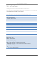
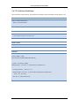
Revision History
Revision History
Revision
Date
Description of Change
1.00
Oct 31, 2011
First revision
i
Preface
Preface
Warranty
All products manufactured by ICP DAS are under warranty regarding defective
materials for a period of one year from the date of delivery to the original purchaser.
Warning
ICP DAS assumes no liability for damages resulting from the use of this product. ICP
DAS reserves the right to change this manual at any time without notice. The information
furnished by ICP DAS is believed to be accurate and reliable. However, no responsibility
is assumed by ICP DAS for its use, or for any infringements of patents or other rights of
third parties resulting from its use.
Copyright
Copyright © 2011 by ICP DAS CO., LTD. All rights are reserved.
Trademark
The names used for identification only may be registered trademarks of their
respective companies.
ii
Content
Content
Revision History .........................................................................................................i
Preface ...................................................................................................................... ii
Content .................................................................................................................... iii
1 Introduction .......................................................................................................... 1
1.1 Overview ..................................................................................................... 1
1.2 Feature ........................................................................................................ 1
1.3 Applications ................................................................................................ 2
1.4 Specifications .............................................................................................. 2
1.4.1 General .............................................................................................. 2
1.4.2 Analog Input ..................................................................................... 3
1.5 Product Check List ...................................................................................... 4
2 Hardware Information .......................................................................................... 5
2.1 Module Overview........................................................................................ 5
2.1.1 USB-2019 .......................................................................................... 6
2.1.2 CN-1824 ............................................................................................ 6
2.2 Connector Pin Assignment ......................................................................... 7
2.2.1 USB-2019 .......................................................................................... 7
2.3 Connector Symbol Description .................................................................. 8
2.3.1 USB-2019 .......................................................................................... 8
2.4 Wiring .......................................................................................................... 8
2.4.1 USB-2019 .......................................................................................... 8
2.5 Hardware Configuration ............................................................................. 8
2.5.1 Board ID............................................................................................. 8
2.5.2 Firmware Update .............................................................................. 9
2.6 LED Indicators ........................................................................................... 10
2.6.1 Normal Operation ........................................................................... 10
2.6.2 Firmware update ............................................................................. 10
3 Installation .......................................................................................................... 11
3.1 Hardware ................................................................................................... 11
3.1.1 Connect to ICP DAS USB I/O series module .................................. 11
3.2 Software .................................................................................................... 11
3.2.1 Utility ............................................................................................... 12
3.2.2 ICP DAS USB I/O SDK Integration .................................................. 17
3.2.3 Samples ........................................................................................... 19
iii
Content
4 Operation ............................................................................................................ 20
4.1 Hardware structure ................................................................................... 20
4.2 Software structure .................................................................................... 20
5 ICP DAS USB Class Members.............................................................................. 24
5.1 Table of Constructors ............................................................................... 24
5.2 Table of Static Methods ............................................................................ 24
5.3 Table of Public Methods ........................................................................... 24
5.3.1 System ............................................................................................. 24
5.3.2 Device .............................................................................................. 25
5.3.3 Analog Input ................................................................................... 25
5.3.4 Pulse Input ...................................................................................... 26
5.3.5 Other ............................................................................................... 27
5.4 Constructors.............................................................................................. 28
5.4.1 ICPDAS_USBIO ................................................................................ 28
5.5 Static Methods .......................................................................................... 29
5.5.1 ListDevice ........................................................................................ 29
5.5.2 ScanDevice ...................................................................................... 30
5.6 Public Methods ......................................................................................... 31
5.6.1 System ............................................................................................. 31
5.6.2 Device .............................................................................................. 36
5.6.3 Analog Input ................................................................................... 57
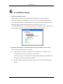
6 Troubleshooting ................................................................................................. 95
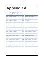
Appendix A ............................................................................................................ 96
A.1 Analog Input Type Code .......................................................................... 96
A.2 Analog Output Type Code ....................................................................... 97
A.3 Pulse Input Type Code ............................................................................. 97
A.4 Channel Status .......................................................................................... 97
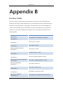
Appendix B ............................................................................................................. 98
B.1 Error Codes ............................................................................................... 98
iv
Introduction
1
Introduction
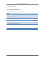
1.1 Overview
ICP DAS USB series I/O modules are highly flexible solution to acquire or output data.
User can build up own PC-based control, laboratory research, testing and so on by
applying ICP DAS USB series modules. The advantages of ICP DAS USB I/O modules are
small size, portable, USB bus powered and various input type to help user build up own
project easily and quickly in different field and application.
Compare with traditional PC I/O card, it is waste of time to open chassis and configure
I/O board. In ICP DAS USB I/O, you will enjoy the simply controlling I/O in the efficient
way. ICP DAS USB I/O equips USB bus powered feature, one cable to access I/O and
provide power without additional power wiring. ICP DAS USB I/O is a small size module.
You can use these I/O modules in wide range application, ex: fan-less control or
measurement, automatically testing with BOX-PC…etc. ICP DAS USB I/O provides 10kS/s
data acquisition functionality. User can apply this to real-time demanded application, ex:
noise measurement.
1.2 Feature
Wide Operating Temperature Range
USB 2.0 Full-Speed
USB Bus Powered
Lockable USB cable
Driver free
10KS/s for analog and pulse input measurement
SDK to develop project easily
All-In-One Utility
1
Introduction
1.3 Applications
Automation
Measurement and testing
Laboratory research
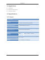
1.4 Specifications
1.4.1 General
Communication
Interface
Watchdog
USB 2.0 Full-Speed
1 Hardware watchdog ( 1.6 second )
1 Software watchdog ( Programmable )
LED Indicators / Display
System LED Indicators
3 LED as Power, Run and Error
I/O LED Indicators
1 LED / channel as I/O status for Digital and Pulse I/O
EMS Protection
ESD ( IEC 61000-4-2 )
4 kV contact for each terminal
8 kV air for random point
Mechanical
Dimensions
Body
33mm × 78mm × 107mm
( W×L×H )
CN-1824
29mm × 43mm × 83mm
Environment
Operating Temperature Range
-25 ~ +75℃
Storage Temperature Range
-40 ~ +85℃
Humidity
10 ~ 95% RH, non-condensing
2
Introduction
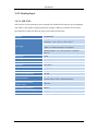
1.4.2 Analog Input
1.4.2.1 USB-2019
USB-2019 is a universal analog input module with 8 differential channels and compatible
with USB 2.0 full-speed. It equips small size, portable, USB bus powered, various input
type features to help user build up own project easily and quickly.
Channels
8 differential
Voltage : ±15 mV, ±50 mV, ±100 mV, ±150 mV,
±500 mV, ±1 V, ±2.5 V, ±5 V, ±10 V
Input Type
Current : ±20 mA, 0 ~ +20 mA, +4 ~ +20 mA
( Note : An external resistor is required )
Thermocouple : J, K, T, E, R, S, B, N, C, L, M and
LDIN43710
Resolution
16 bit
Accuracy
±0.1% FSR
Sampling Rate
10 Hz ( Total )
Zero Drift
±20 μV/℃
Span Drift
±25 ppm/℃
Common Mode Rejection
86 dB
Normal Mode Rejection
100 dB
Input Impedance
Intra-Module Isolation,
Field-to-Logic
Voltage input : > 400 kΩ
Current input : 125Ω (External resistor)
3000 VDC
Overvoltage protection
240 Vrms
Individual Channel Configuration
Yes
Open Wire Detection
Yes (Software programmable)
3
Introduction
1.5 Product Check List
The package includes the following items:
One ICP DAS USB I/O module
One Quick Start Guide
One USB cable with lockable kit
It is highly recommended to read the Quick Start Guide first before using USB I/O
modules. The following useful information will be given in the Quick Start Guide:
How to install hardware and use utility
4
Hardware Information
2
Hardware Information
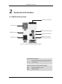
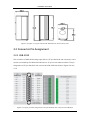
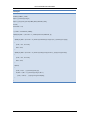
2.1 Module Overview
LEDs & I/Os Terminal
Frame Ground
Board ID Rotary Switch
DIN Rail Mount
USB Type B connector
Normal / Firmware
update Mode Switch
DIN Rail Lock
Figure 2-1 Module Overview of ICP DAS USB I/O
Board ID Rotary Switch
0
: User defined (Software Programmable)
1 ~ 15
: Fix board ID
Normal / Firmware Update Mode Switch
INIT
: Firmware update mode
RUN
: Normal mode
5
Hardware Information
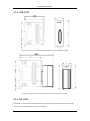
2.1.1 USB-2019
Figure 2-2, Figure 2-3 USB-2019 left side and front view without CN-1824
Figure 2-4, Figure 2-5 USB-2019 left side and front view with CN-1824
2.1.2 CN-1824
CN-1824 is a connector transfer DB-25 pin connector to 18 pin terminal block to help
user to wire. The dimension is shown as follow.
6
Hardware Information
Figure 2-6, Figure 2-7, Figure 2-8 The CN-1824 left side, front and top view
2.2 Connector Pin Assignment
2.2.1 USB-2019
The connector of USB-2019 analog input side is a 25-pin female D-sub connector, and it
can be connected by CN-1824 terminal block or 25-pin D-sub male connector. The pin
assignment of 25-pin female D-sub connect and CN-1824 are shown in figure 2-9 and
2-10.
Figure 2-9 , Figure 2-10 Pin assignment of 25-pin female D-sub connector and CN-1824
7
Hardware Information
2.3 Connector Symbol Description
2.3.1 USB-2019
Signal
Direction
Description
AGND
I
Analog input ground
CH<N>+
I
Analog input channel N positive reference.
CH<N>-
I
Analog input channel N negative reference.
2.4 Wiring
2.4.1 USB-2019
Voltage Input
Thermocouple Input
Current Input
Note: When connecting to current source, an
external 125Ω resistor is required.
2.5 Hardware Configuration
ICP DAS USB module provides two basic hardware configurations for each module to
configure board ID and enable firmware update.
2.5.1 Board ID
The ID is used to identify two same product number modules connecting to computer.
When two more same product number modules are connected, each of them must be
set to different ID to prevent conflict and unexpected errors. It can be configured
through the rotary switch on the bottom of device. The location of the rotary switch is
8
Hardware Information
shown in figure 2-11. The value of ID can be configured from 1 ~ 15 by hardware, and
can be configured from 16 ~ 127 by software when switch to 0.
Figure 2-11 Hardware setting for board ID
2.5.2 Firmware Update
ICP DAS USB modules provide updatable functionality. User can switch to firmware
update mode when latest firmware released. The switch setting is shown in figure 2-12.
Switch to INIT. to enable firmware update functionality.
Figure 2-12 Hardware setting for enabling firmware update functionality
9
Hardware Information
2.6 LED Indicators
ICP DAS USB modules have two modes, normal and firmware update, as previous
section mentioned. Each mode has own LED indication. The LED status for these two
modes is shown below.
2.6.1 Normal Operation
LED Indicators
LED Status
Causes
PWR (Yellow)
Blink
HW WDT triggered
Solid
Normal Operation
Off
Power Off
Blink
USB Bus Communicating
Off
USB Bus Idle
Blink (Less frequent)
Warning (Does not affect the operation)
Blink
Minor Error (Does not affect the operation)
Solid
Major Error (Does affect the operation)
Off
No Error
RUN (Green)
ERR (Red)
2.6.2 Firmware update
LED Indicators
LED Status
Causes
ALL
Blink
Waiting for Firmware to update
10
Installation
3
Installation
3.1 Hardware
3.1.1 Connect to ICP DAS USB I/O series module
1.
Turn on the PC you are preparing to configure and program.
2.
Connect ICP DAS USB I/O module to USB 2.0 port or higher on PC by using cable
inside the box.
3.
Once you first time connect USB I/O module to PC, there will be few message in
system bar in bottom right side to inform new hardware is detect and installed
successfully. After the message shown as figure 3-2, then USB I/O module is ready
to use.
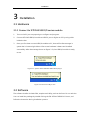
Figure 3-1 System detect ICPDAS USB module plug in
Figure 3-2 Device is ready to use
3.2 Software
The software installer includes SDK, samples and Utility, and can be found in our web site.
You can install the package by double clicking the file “ICPDAS USB IO X.X.X.exe”, and
follow the instruction during installation process.
11
Installation
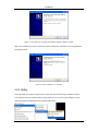
Figure 3-3 The welcome message of ICP DAS USB I/O software installer
After the installation process, the window will indicate the installation has completed as
the figure below.
Figure 3-4 The installation is complete
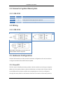
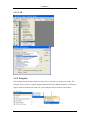
3.2.1 Utility
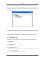
USB-2K Utility provides a simple way to easily test and instant acquire data for all ICP
DAS USB I/O series modules without programming. You can find this program in the
“Start\Programs\ICPDAS\ICP DAS USB IO\USB Utility”.
12
Installation
Once the utility open, the all ICP DAS USB I/O modules connected to PC are listed in
“Device List” tree view of device list form as figure 3-5. The utility will scan ICP DAS USB
IO modules automatically, the module in the list view will be removed when pull off and
added when plug in.
Figure 3-5 USB Utility Device List form
To access ICP DAS USB I/O module by double clicking module in device list, then you will
see another form come out. There are several function pages, information to configure
basic system parameters, I/O access (DI/O, AI/O, PI/O) to monitor real-time data and
configure I/O parameters and data log (if module supports this function), in this form.
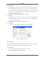
3.2.1.1 Information Page
In “Information” page, the detail of all items in this page will be introduced as follow:
Device Name
The name of the opened device.
Firmware Version
The firmware version of the opened device.
User Defined Board ID
The board ID of the opened device. The value can be configured when switch the ID
to “0” by the rotary switch.
Note: The valid range of this ID is from 16 ~ 127.
13
Installation
Software WDT
The software watch dog timer of the opened device. The value used to enable the
check of module alive. When enable the watch dog timer, computer and module
will send SYNC packet each other. The period to send is a quarter of this WDT value.
This value also provides the module has output capability to enable safety value
output when communication is failure.
Note: The valid range of this value is 100 ms ~ 30 minute.
Description
The description of the opened device. This item used to help user identify module.
For example: Name the description to “LAB1-CTL”. So, this message help user to
know what this module used for.
Note: The maximum characters of description are 32.
Load Default
This function helps user to restore module to factory default setting.
Figure 3-6 USB I/O Information Page
3.2.1.2 AI Page
In “IO” page, the real-time value and module configuration can be read or written in this
page. The detail of all of item in this form will be introduced as follow.
Polling Interval
This value is the period of polling data from USB I/O module.
Note: The range of this value is 100 ~ 5000ms.
14
Installation
Hide Setting Panel
This checkbox used to hide the I/O configuration panel when user only wants to
take care of I/O data.
Show Hex
This checkbox use to convert the I/O value from decimal to hexadecimal.
I/O Monitor Region
The I/O related data and configuration will be listed here. User can select the
channel to configure corresponding setting in I/O configuration region. The setting
of this selected channel will show in I/O configuration.
I/O Configuration Region
All AI related configuration can be set in this region. This region is divided to part,
channel and module related setting. The channel related setting is in “Selected
Channel” group box. The rest of group boxes are module related setting.
Set All
Channel related setting will be followed by currently selection.
Type
ICP DAS USB I/O modules provide programmable input type on analog input.
You can set different type for each analog input channel. Selecting the type in
the combo box you want.
For more detail on input type of analog input modules, please refer to
“Appendix B”.
Channel Enable
Enable / Disable channel.
Channel CJC Offset
Set the CJC offset of the specified channel individually. This feature behaves
the same as the CJC Offset, except that it only affects a single channel. By
default, this offset value is zero.
Note: The CJC offset can be any in the range of -40.96 to +40.95 °C.
Filter Rejection
In order to remove the noise from the power supply, analog input modules
feature build-in filter. Two filters with different frequencies are provided to
remove noise generated from different power source.
15
Installation
Wire Detection
Enable / Disable the open-wire detection for thermocouple measurement.
CJC Enable
Enable / Disable the CJC (Cold-junction compensation).
CJC Offset
Set the CJC offset value for all AI channels. The offset value is used to add or
subtract a temperature measured by the CJC sensor. By default, this offset
value is zero. Change of this value does not affect calibration, but will affect
the displayed temperature. If an offset error is occurring with the CJC sensor,
this feature may be used to reduce or eliminate that error.
Note: The CJC offset can be any in the range of -40.96 to +40.95 °C.
Figure 3-7 USB I/O AI Configuration Page
16
Installation
3.2.2 ICP DAS USB I/O SDK Integration
The SDK is the way to access ICP DAS USB I/O modules. The SDK supports various IDE
like C#.NET/VB.NET/VB/VC/BCB. You can choose what IDE you familiar with. Before
starting up your own project, you need to do some configuration to integrate the SDK
into your IDE. The following section will indicate you how to integrate the SDK into your
IDE.
Another way to start your own application is copying sample project folder then
developing your project.
3.2.2.1 .NET
17
Installation
3.2.2.2 VC
3.2.2.3 BCB
This section is left blank intentionally.
18
Installation
3.2.2.4 VB
3.2.3 Samples
The package also provides samples to help user to develop own project smoothly. The
samples can be found in “Start\Programs\ICPDAS\ICP DAS USB IO\Samples” as following
figure. Another window will come out, and all samples will be listed in the window.
19
Operation
4
Operation
4.1 Hardware structure
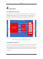
ICP DAS USB I/O provides various types of input and output for user’s application. ICP
DAS USB I/O has two solution, one is compact I/O another is multi-function. The I/O
controller is handled by embedded controller. This controller uses GPIO or FPGA to
control read or write I/O. The hardware structure is shown in figure 4-1 below.
ICP DAS USB IO
DI
Embedded
controller
DO
AI
External
Memory
EEPROM
AO
PI
Input / Output
USB Host (Computers)
FPGA
PO
Figure 4-1 Hardware structure of ICP DAS USB series module
4.2 Software structure
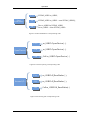
In programmer side, ICP DAS provides a class library to develop your own project quickly
and easily. The structure of ICP DAS USB I/O software is shown in figure 4-2 below. The
methods of USB class are divided into 4 group, base, digital I/O, analog I/O and pulse I/O.
To access USB I/O, there are only 2 steps, class initialization and opening device, in your
own program.
20
Operation
Figure 4-2 Software structure of ICP DAS USB series module
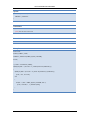
Class
Initialization
Access I/O
DI_...
DO_...
AI_...
AO_...
PI_...
PO_...
OpenDevice
Figure 4-3 The procedure to access USB I/O
21
CloseDevice
Operation
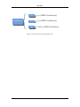
{
Class
Initialization
C++
ICPDAS_USBIO m_USBIO;
C#
ICPDAS_USBIO m_USBIO = new ICPDAS_USBIO();
VB
Dim m_USBIO As ICPDAS_USBIO
Set m_USBIO = New ICPDAS_USBIO
Figure 4-4 Class initialization corresponding code
{
OpenDevice
C++
m_USBIO.OpenDevice(…);
C#
m_USBIO.OpenDevice(…);
VB
Call m_USBIO.OpenDevice(…)
Figure 4-5 Device opening corresponding code
{
Access I/O
C++
m_USBIO.AI_ReadValue(…);
C#
m_USBIO.AI_ReadValue(…);
VB
Call m_USBIO.AI_ReadValue(…)
Figure 4-6 Accessing I/O corresponding code
22
Operation
{
CloseDevice
C++
m_USBIO.CloseDevice();
C#
m_USBIO.CloseDevice();
VB
Call m_USBIO.CloseDevice
Figure 4-7 Device closing corresponding code
23
ICP DAS USB Class Members
5
ICP DAS USB Class Members
The members of ICPDAS_USBIO are divided into 3 parts are constructors, static and
public methods. Constructors are initializations to create instance of the ICPDAS_USBIO
class. Static methods are the ways to identify or scan what ICP DAS USB modules
plugged in. Public methods are the core to access ICP DAS USB modules. It provides the
functionalities of system, device, digital, analog, pulse input or output.
The following tables list the members of ICPDAS_USBIO class. The detail of these
methods will be described in the following chapter.
5.1 Table of Constructors
Name
Description
ICPDAS_USBIO
Initializes a new instance of the ICPDAS_USBIO class.
5.2 Table of Static Methods
Name
Description
ListDevice
List all devices connected with local PC.
ScanDevice
Scan devices connected with local PC
5.3 Table of Public Methods
5.3.1 System
Name
Description
OpenDevice
List all devices connected with local PC.
CloseDevice
Scan devices connected with local PC.
SYNCDevice
Send a synchronization packet to clear software
WDT.
SetCommTimeout
Set communication timeout.
GetCommTimeout
Get communication timeout.
24
ICP DAS USB Class Members
5.3.2 Device
Name
Description
RefreshDeviceInfo
Refresh device information.
GetSoftWDTTimeout
Get software WDT timeout.
GetDeviceID
Get ID of the device.
GetFwVer
Get firmware version of the device.
GetDeviceNickName
Get nick name of the device.
GetDeviceSN
Get serial number of the device.
GetSupportIOMask
Get the mask of this device IO distribution.
GetDITotal
Get DI total channel of the device.
GetDOTotal
Get DO total channel of the device.
GetAITotal
Get AI total channel of the device.
GetAOTotal
Get AO total channel of the device.
GetPITotal
Get PI total channel of the device.
GetPOTotal
Get PO total channel of the device.
SetUserDefinedBoardID
Set board ID of this device.
SetDeviceNickName
Set nick name of this device.
SetSoftWDTTimeout
Set software WDT timeout.
LoadDefault
Load default setting.
StopBulk
Stop current bulk process.
RegisterEmergencyPktEventHandle Register the callback function for emergency event
sent from USBIO.
5.3.3 Analog Input
Name
Description
AI_GetTotalSupportType
Analog input function - Get total supported
amount.
AI_GetSupportTypeCode
Analog input function - Get supported type code.
AI_GetTypeCode
Analog input function - Get type code.
AI_GetChCJCOffset
Analog input function - Get channel CJC offset.
AI_GetChEnable
Analog input function - Get channel enable/disable.
AI_GetFilterRejection
Analog input function - Get filter rejection.
AI_GetCJCOffset
Analog input function - Get CJC offset.
AI_GetCJCEnable
Analog input function - Get CJC enable.
AI_GetWireDetectEnable
Analog input function - Get wire detect enable.
25
ICP DAS USB Class Members
AI_GetResolution
Analog input function - Get resolution.
AI_ReadValue
Analog input function - Read AI value in double
word format. (Overload)
AI_ReadBulkValue
Analog input function - Read bulk AI value (Fast
acquire functionality)
AI_ReadCJCValue
Analog input function - Get CJC value.
AI_SetTypeCode
Analog input function - Set type code for specific
channel. (Overload)
AI_SetChCJCOffset
Analog input function - Set channel CJC offset for
specific channel. (Overload)
AI_SetChEnable
Analog input function - Set channel enable/disable.
AI_SetFilterRejection
Analog input function - Set filter rejection.
AI_SetCJCOffset
Analog input function - Set CJC offset.
AI_SetCJCEnable
Analog input function - Set CJC enable.
AI_SetWireDetectEnable
Analog input function - Set wire detect enable.
5.3.4 Pulse Input
Name
Description
PI_GetTotalSupportType
Pulse input function - Get total supported amount.
PI_GetSupportTypeCode
Pulse input function - Get supported type code.
PI_GetTypeCode
Pulse input function - Get type code.
PI_GetTriggerMode
Pulse input function - Get trigger mode.
PI_GetLPFilterEnable
Pulse input function - Get low-pass filter enable.
PI_GetLPFilterWidth
Pulse input function - Get low-pass filter width.
PI_ReadValue
Pulse input function - Get PI value.
PI_ReadBulkValue
Pulse input function - Get bulk PI value (Fast acquire
functionality)
PI_SetTypeCode
Pulse input function - Set type code for specific
channel. (Overload)
PI_ClearChCount
Pulse input function - Clear specific channel count.
PI_ClearAllChCount
Pulse input function - Clear all channel count.
PI_SetTriggerMode
Pulse input function - Set trigger mode. (Overload)
PI_SetLPFilterEnable
Pulse input function - Set low-pass filter enable.
(Overload)
PI_SetLPFilterWidth
Pulse input function - Set low-pass filter width.
(Overload)
26
ICP DAS USB Class Members
5.3.5 Other
Name
Description
GetCurrentAccessObj
INTERNAL USE. DO NOT USE THIS METHOD.
SetNormalPktByteArray
INTERNAL USE. DO NOT USE THIS METHOD.
SetActivePktByteArray
INTERNAL USE. DO NOT USE THIS METHOD.
ClearActivePktBuffer
INTERNAL USE. DO NOT USE THIS METHOD.
GetActivePktByteArray
INTERNAL USE. DO NOT USE THIS METHOD.
SetNormalPktEvent
INTERNAL USE. DO NOT USE THIS METHOD.
IsDevMonitorThreadStop
INTERNAL USE. DO NOT USE THIS METHOD.
IsCommWithDevice
INTERNAL USE. DO NOT USE THIS METHOD.
GetLastCmdTime
INTERNAL USE. DO NOT USE THIS METHOD.
27
ICP DAS USB Class Members
5.4 Constructors
5.4.1 ICPDAS_USBIO
Initialize a new instance of the ICPDAS_USBIO class.
Syntax
public ICPDAS_USBIO (
void
)
Example
ICPDAS_USBIO m_usbIO;
m_usbIO = new ICPDAS_USBIO();
28
ICP DAS USB Class Members
5.5 Static Methods
5.5.1 ListDevice
List all devices connected with local PC.
Syntax
public byte ListDevice (
WORD *o_wDID,
BYTE *o_byBID
)
Parameters
*o_wDID
[OUT] An array of device ID for all devices
*o_byBID
[OUT] An array of board ID for all devices
Return Value
Number of devices connected with PC
Example
BYTE byNumDevice, byBIDs[127];
WORD wDIDs[127];
byNumDevice = ICPDAS_USBIO.ListDevice(&wDIDs, &byBIDs);
29
ICP DAS USB Class Members
5.5.2 ScanDevice
Scan device connected to PC. This static method just refreshes the list of ICP DAS USB
I/O modules, it is necessary to call ListDevice() to get new list.
Syntax
public int ScanDevice (
void
)
Parameters
none
Return Value
Error code
Example
ICPDAS_USBIO.ScanDevice();
30
ICP DAS USB Class Members
5.6 Public Methods
5.6.1 System
5.6.1.1 OpenDevice
Open USBIO with device ID and board ID. The device ID is defined by the header
ICPDAS_USBIO.h or the enumeration in ICPDAS_USBIO.
Syntax
public int OpenDevice (
WORD i_wUSBIO_DID,
BYTE i_byUSBIO_BID
)
Parameters
i_wUSBIO_DID
[IN] Device ID for the specific device to open (Defined in ICPDAS_USBIO.h)
i_byUSBIO_BID
[IN] Board ID for the specific device to open
Return Value
Error code
Example
Int iErrCode;
ICPDAS_USBIO m_usbIO;
m_usbIO = new ICPDAS_USBIO();
iErrCode = m_usbIO.OpenDevice(USB2019, 1);
iErrCode = m_usbIO.CloseDevice();
31
ICP DAS USB Class Members
5.6.1.2 CloseDevice
Close device and release resource.
Syntax
public int CloseDevice (
void
)
Parameters
none
Return Value
Error code
Example
Int iErrCode
ICPDAS_USBIO m_usbIO;
m_usbIO = new ICPDAS_USBIO();
if (ERR_NO_ERR == (iErrCode = m_usbIO.OpenDevice(USB2019, 1)))
{
// Some code accessing USB I/O
iErrCode = m_usbIO.CloseDevice();
}
32
ICP DAS USB Class Members
5.6.1.3 SYNCDevice
Send synchronization packet to I/O module.
Note 1: The synchronization will be handled by library after calling OpenDevice, the
procedure will be closed after calling CloseDevice. User can call this API to send
synchronization packet manually, it will not stop the original synchronization procedure
handled by library.
Syntax
public int SYNCDevice (
void
)
Parameters
none
Return Value
Error code
Example
Int iErrCode
ICPDAS_USBIO m_usbIO;
m_usbIO = new ICPDAS_USBIO();
if (ERR_NO_ERR == (iErrCode = m_usbIO.OpenDevice(USB2019, 1)))
{
If(ERR_NO_ERR != (iErrCode = m_usbIO.SYNCDevice()))
printf(“%d”, iErrCode);
iErrCode = m_usbIO.CloseDevice();
}
33
ICP DAS USB Class Members
5.6.1.4 SetCommTimeout
Set the communication timeout between packet send and receive.
Note 1: The timeout value will affect communication. If the timeout is small, it means the
communication is timeout after the value passed.
Note 2: The default value when first initial an ICP DAS USB I/O is 100ms.
Syntax
public int SetCommTimeout (
DWORD i_dwCommTimeout
)
Parameters
i_dCommTimeout
[IN] The communication timeout in millisecond(ms)
Return Value
Error code
Example
Int iErrCode
ICPDAS_USBIO m_usbIO;
m_usbIO = new ICPDAS_USBIO();
if(ERR_NO_ERR != (iErrCode = m_usbIO.SetCommTimeout(1000)))
printf(“%d”, iErrCode)
34
ICP DAS USB Class Members
5.6.1.5 GetCommTimeout
Get the communication timeout between packet send and receive.
Note 1: The timeout value will affect communication. If the timeout is small, it means the
communication is timeout after the value passed.
Note 2: The default value when first initial an ICP DAS USB I/O is 100ms.
Syntax
public int GetCommTimeout (
DWORD* o_dwCommTimeout
)
Parameters
o_dCommTimeout
[OUT] The communication timeout in millisecond(ms)
Return Value
Error code
Example
Int iErrCode
ICPDAS_USBIO m_usbIO;
DWORD o_dwCommTimeout;
m_usbIO = new ICPDAS_USBIO();
if (ERR_NO_ERR == (iErrCode = m_usbIO.SetCommTimeout(1000)))
if(ERR_NO_ERR != (iErrCode = m_usbIO. GetCommTimeout (&o_dwCommTimeout)))
printf(“%d”, iErrCode);
else
printf(“%d\n”, o_dwCommTimeout);
35
ICP DAS USB Class Members
5.6.2 Device
5.6.2.1 RefreshDeviceInfo
Refresh all information of this device.
Note 1: The RefreshDeviceInfo() will be called automatically when open device.
Note 2: This function will take time to refresh information.
Syntax
public int RefreshDeviceInfo (
void
)
Parameters
none
Return Value
Error code
Example
Int iErrCode
ICPDAS_USBIO m_usbIO;
m_usbIO = new ICPDAS_USBIO();
if(ERR_NO_ERR == (iErrCode = m_usbIO.OpenDevice(USB2019, 1)))
{
if(ERR_NO_ERR != iErrCode = m_usbIO.RefreshDeviceInfo()))
printf(“%d”, iErrCode)
iErrCode = m_usbIO.CloseDevice();
}
36
ICP DAS USB Class Members
5.6.2.2 GetSoftWDTTimeout
Get the software WDT timeout of I/O module.
Syntax
public int GetSoftWDTTimeout (
DWORD *o_dwSoftWDTTimeout
)
Parameters
*o_dwSoftWDTTimeout
[OUT] The software WDT timeout in millisecond(ms)
Return Value
Error code
Example
Int iErrCode
ICPDAS_USBIO m_usbIO;
DWORD o_dwSoftWDTTimeout;
m_usbIO = new ICPDAS_USBIO();
if(ERR_NO_ERR == (iErrCode = m_usbIO.OpenDevice(USB2019, 1)))
{
if(ERR_NO_ERR != iErrCode = m_usbIO. GetSoftWDTTimeout (&o_dwSoftWDTTimeout)))
printf(“%d”,iErrCode);
else
printf(“%d\n”, o_dwCommTimeout);
iErrCode = m_usbIO.CloseDevice();
}
37
ICP DAS USB Class Members
5.6.2.3 GetDeviceID
Get ID of the device.
Syntax
public int GetDeviceID (
DWORD *o_dwDeviceID
)
Parameters
*o_dwDeviceID
[OUT] The device ID
Return Value
Error code
Example
Int iErrCode
ICPDAS_USBIO m_usbIO;
DWORD o_dwDeviceID;
m_usbIO = new ICPDAS_USBIO();
if(ERR_NO_ERR == (iErrCode = m_usbIO.OpenDevice(USB2019, 1)))
{
if(ERR_NO_ERR != (iErrCode = m_usbIO. GetDeviceID (&o_dwDeviceID)))
printf(“%d”, iErrCode);
else
printf(“%d”, o_dwDeviceID);
iErrCode = m_usbIO.CloseDevice();
}
38
ICP DAS USB Class Members
5.6.2.4 GetFwVer
Get firmware version of the device.
Syntax
public int GetDeviceID (
WORD *o_ wFwVer
)
Parameters
*o_wFwVer
[OUT] The firmware version
Return Value
Error code
Example
Int iErrCode
ICPDAS_USBIO m_usbIO;
WORD o_wFwVer;
m_usbIO = new ICPDAS_USBIO();
if(ERR_NO_ERR == (iErrCode = m_usbIO.OpenDevice(USB2019, 1)))
{
if(ERR_NO_ERR != (iErrCode = m_usbIO. GetFwVer (&o_wFwVer)))
printf(“%d”, iErrCode);
else
printf(“%d”,o_wDwVer);
iErrCode = m_usbIO.CloseDevice();
}
39
ICP DAS USB Class Members
5.6.2.5 GetDeviceNickName
Get nick name of the device.
Syntax
public int GetDeviceNickName (
BYTE *o_byDeviceNickName
)
Parameters
*o_byDeviceNickName
[OUT] The byte array of the nick name of the device
Return Value
Error code
Example
Int iErrCode
ICPDAS_USBIO m_usbIO;
Byte o_byDeviceNickName [USBIO_NICKNAME_LENGTH];
m_usbIO = new ICPDAS_USBIO();
if(ERR_NO_ERR == (iErrCode = m_usbIO.OpenDevice(USB2019, 1)))
{
if(ERR_NO_ERR != (iErrCode = m_usbIO. GetDeviceNickName (o_byDeviceNickName)))
printf(“%d”, iErrCode);
else
printf(“%s”, o_byDeviceNickName);
iErrCode = m_usbIO.CloseDevice();
}
40
ICP DAS USB Class Members
5.6.2.6 GetDeviceSN
Get serial number of the device.
Syntax
public int GetDeviceSN (
BYTE *o_byDeviceSN
)
Parameters
*o_byDeviceSN
[OUT] The byte array of the serial number of the device
Return Value
Error code
Example
Int iErrCode
ICPDAS_USBIO m_usbIO;
Byte o_byDeviceSN [USBIO_SN_LENGTH];
m_usbIO = new ICPDAS_USBIO();
if(ERR_NO_ERR == (iErrCode = m_usbIO.OpenDevice(USB2019, 1)))
{
if(ERR_NO_ERR != (iErrCode = m_usbIO. GetDeviceSN (o_ byDeviceSN)))
printf(“%d”, iErrCode);
else
printf(“%s”, o_ byDeviceSN);
iErrCode = m_usbIO.CloseDevice();
}
41
ICP DAS USB Class Members
5.6.2.7 GetSupportIOMask
Get the mask of this device IO distribution. Each bit of the mask indicates each
supported IO type as shown in the following table.
Bit7
Bit6
Bit5
Bit4
Bit3
Bit2
Bit1
Bit0
N/A
N/A
PI
PO
AI
AO
DI
DO
This mask can help you to identify what types of IO are supported in the device.
Syntax
public int GetSupportIOMask (
BYTE *o_bySupportIOMask
)
Parameters
*o_bySupportIOMask
[OUT] The support IO mask of the device
Return Value
Error code
42
ICP DAS USB Class Members
Example
Int iErrCode
ICPDAS_USBIO m_usbIO;
Byte o_bySupportIOMask;
m_usbIO = new ICPDAS_USBIO();
if(ERR_NO_ERR == (iErrCode = m_usbIO.OpenDevice(USB2019, 1)))
{
if(ERR_NO_ERR != (iErrCode = m_usbIO. GetSupportIOMask (&o_bySupportIOMask)))
printf(“%d”, iErrCode);
else
printf(“0x%02x”,o_bySupportIOMask);
iErrCode = m_usbIO.CloseDevice();
}
43
ICP DAS USB Class Members
5.6.2.8 GetDITotal
Get DI total number of channels of the device.
Syntax
public int GetDITotal (
BYTE *o_byDITotal
)
Parameters
*o_byDITotal
[OUT] The DI total number of channels
Return Value
Error code
Example
Int iErrCode
ICPDAS_USBIO m_usbIO;
Byte o_byDITotal;
m_usbIO = new ICPDAS_USBIO();
if(ERR_NO_ERR == (iErrCode = m_usbIO.OpenDevice(USB20xx, 1)))
{
if(ERR_NO_ERR != (iErrCode = m_usbIO. GetDITotal (&o_byDITotal)))
printf(“%d”, iErrCode);
else
printf(“%d”,o_byDITotal);
iErrCode = m_usbIO.CloseDevice();
}
44
ICP DAS USB Class Members
5.6.2.9 GetDOTotal
Get DO total number of channels of the device.
Syntax
public int GetDOTotal (
BYTE *o_byDOTotal
)
Parameters
*o_byDOTotal
[OUT] The DO total number of channels
Return Value
Error code
Example
Int iErrCode
ICPDAS_USBIO m_usbIO;
Byte o_byDOTotal;
m_usbIO = new ICPDAS_USBIO();
if(ERR_NO_ERR == (iErrCode = m_usbIO.OpenDevice(USB20xx, 1)))
{
if(ERR_NO_ERR != (iErrCode = m_usbIO. GetDOTotal (&o_byDOTotal)))
printf(“%d”, iErrCode);
else
printf(“%d”,o_byDOTotal);
iErrCode = m_usbIO.CloseDevice();
}
45
ICP DAS USB Class Members
5.6.2.10 GetAITotal
Get AI total number of channels of the device.
Syntax
public int GetAITotal (
BYTE *o_byAITotal
)
Parameters
*o_byAITotal
[OUT] The AI total number of channels
Return Value
Error code
Example
Int iErrCode
ICPDAS_USBIO m_usbIO;
Byte o_byAITotal;
m_usbIO = new ICPDAS_USBIO();
if(ERR_NO_ERR == (iErrCode = m_usbIO.OpenDevice(USB20xx, 1)))
{
if(ERR_NO_ERR != (iErrCode = m_usbIO. GetAITotal (&o_byAITotal)))
printf(“%d”, iErrCode);
else
printf(“%d”,o_byAITotal);
iErrCode = m_usbIO.CloseDevice();
}
46
ICP DAS USB Class Members
5.6.2.11 GetAOTotal
Get AO total number of channels of the device.
Syntax
public int GetAOTotal (
BYTE *o_byAOTotal
)
Parameters
*o_byAOTotal
[OUT] The AO total number of channels
Return Value
Error code
Example
Int iErrCode
ICPDAS_USBIO m_usbIO;
Byte o_byAOTotal;
m_usbIO = new ICPDAS_USBIO();
if(ERR_NO_ERR == (iErrCode = m_usbIO.OpenDevice(USB20xx, 1)))
{
if(ERR_NO_ERR != (iErrCode = m_usbIO. GetAOTotal (&o_byAOTotal)))
printf(“%d”, iErrCode);
else
printf(“%d”,o_byAOTotal);
iErrCode = m_usbIO.CloseDevice();
}
47
ICP DAS USB Class Members
5.6.2.12 GetPITotal
Get PI total number of channels of the device.
Syntax
public int GetPITotal (
BYTE *o_byPITotal
)
Parameters
*o_byPITotal
[OUT] The PI total number of channels
Return Value
Error code
Example
Int iErrCode
ICPDAS_USBIO m_usbIO;
Byte o_byPITotal;
m_usbIO = new ICPDAS_USBIO();
if(ERR_NO_ERR == (iErrCode = m_usbIO.OpenDevice(USB20xx, 1)))
{
if(ERR_NO_ERR != (iErrCode = m_usbIO. GetPITotal (&o_byPITotal)))
printf(“%d”, iErrCode);
else
printf(“%d”,o_byPITotal);
iErrCode = m_usbIO.CloseDevice();
}
48
ICP DAS USB Class Members
5.6.2.13 GetPOTotal
Get PO total number of channels of the device.
Syntax
public int GetPOTotal (
BYTE *o_byPOTotal
)
Parameters
*o_byPOTotal
[OUT] The PO total number of channels
Return Value
Error code
Example
Int iErrCode
ICPDAS_USBIO m_usbIO;
Byte o_byPOTotal;
m_usbIO = new ICPDAS_USBIO();
if(ERR_NO_ERR == (iErrCode = m_usbIO.OpenDevice(USB20xx, 1)))
{
if(ERR_NO_ERR != (iErrCode = m_usbIO. GetPOTotal (&o_byPOTotal)))
printf(“%d”, iErrCode);
else
printf(“%d”,o_byPOTotal);
iErrCode = m_usbIO.CloseDevice();
}
49
ICP DAS USB Class Members
5.6.2.14 SetUserDefinedBoardID
Set board ID of this device. The valid value of the ID is from 16 to 127.
Syntax
public int SetUserDefinedBoardID (
BYTE i_byBID
)
Parameters
i_byBID
[IN] The board ID to set
Return Value
Error code
Example
Int iErrCode
ICPDAS_USBIO m_usbIO;
m_usbIO = new ICPDAS_USBIO();
if(ERR_NO_ERR == (iErrCode = m_usbIO.OpenDevice(USB20xx, 1)))
{
if(ERR_NO_ERR != (iErrCode = m_usbIO. SetUserDefinedBoardID (123)))
printf(“%d”, iErrCode);
iErrCode = m_usbIO.CloseDevice();
}
50
ICP DAS USB Class Members
5.6.2.15 SetDeviceNickName
Set nick name of this device. The maximum number of the character of this device is 32.
Syntax
public int SetDeviceNickName (
BYTE *i_byDeviceNickName
)
Parameters
*i_byDeviceNickName
[IN] The byte array of the nick name to set
Return Value
Error code
Example
Int iErrCode
ICPDAS_USBIO m_usbIO;
Byte byNickName[USBIO_NICKNAME_LENGTH];
m_usbIO = new ICPDAS_USBIO();
if(ERR_NO_ERR == (iErrCode = m_usbIO.OpenDevice(USB20xx, 1)))
{
sprintf(byNickName, “Station 1-1-3”);
if(ERR_NO_ERR != (iErrCode = m_usbIO. SetDeviceNickName (byNickName)))
printf(“%d”, iErrCode);
iErrCode = m_usbIO.CloseDevice();
}
51
ICP DAS USB Class Members
5.6.2.16 SetSoftWDTTimeout
Set the software WDT timeout.
The minimum value of timeout is 100ms, and maximum is 30 minutes.
Syntax
public int SetSoftWDTTimeout (
DWORD i_dwSoftWDTTimeout
)
Parameters
i_dwSoftWDTTimeout
[IN] The software WDT timeout in millisecond(ms)
Return Value
Error code
Example
Int iErrCode
ICPDAS_USBIO m_usbIO;
m_usbIO = new ICPDAS_USBIO();
if(ERR_NO_ERR == (iErrCode = m_usbIO.OpenDevice(USB20xx, 1)))
{
if(ERR_NO_ERR != (iErrCode = m_usbIO. SetSoftWDTTimeout (1000)))
printf(“%d”, iErrCode);
iErrCode = m_usbIO.CloseDevice();
}
52
ICP DAS USB Class Members
5.6.2.17 LoadDefault
Load default setting.
Syntax
public int LoadDefault (
void
)
Parameters
none
Return Value
Error code
Example
Int iErrCode
ICPDAS_USBIO m_usbIO;
m_usbIO = new ICPDAS_USBIO();
if (ERR_NO_ERR == (iErrCode = m_usbIO.OpenDevice(USB20xx, 1)))
{
If(ERR_NO_ERR != (iErrCode = m_usbIO.LoadDefault ()))
printf(“%d”, iErrCode);
iErrCode = m_usbIO.CloseDevice();
}
53
ICP DAS USB Class Members
5.6.2.18 StopBulk
Stop current bulk process.
Syntax
public int LoadDefault (
void
)
Parameters
none
Return Value
Error code
Example
Int iErrCode
ICPDAS_USBIO m_usbIO;
m_usbIO = new ICPDAS_USBIO();
if (ERR_NO_ERR == (iErrCode = m_usbIO.OpenDevice(USB20xx, 1)))
{
If(ERR_NO_ERR != (iErrCode = m_usbIO.StopBulk ()))
printf(“%d”, iErrCode);
iErrCode = m_usbIO.CloseDevice();
}
54
ICP DAS USB Class Members
5.6.2.19 RegisterEmergencyPktEventHandle
Register the callback function for emergency event sent from USBIO.
When in callback operation, it will cause the performance in your callback function.
Please reduce execute time in this callback function.
Syntax
public int RegisterEmergencyPktEventHandle (
OnEmergencyPktArriveEvent i_evtHandle
)
Parameters
i_evtHandle
[IN] The callback function for emergency event
Return Value
Error code
55
ICP DAS USB Class Members
Example
Int iErrCode
ICPDAS_USBIO m_usbIO;
Bool m_bEmcyPktArrive;
Byte byEmcyPkt[USBIO_MAX_PACKET_LENGTH];
Void emcypkeEvt(Byte* byData, Byte byLen)
{
m_ bEmcyPktArrive = true;
memcpy(byEmcyPkt, byData, byLen);
}
m_usbIO = new ICPDAS_USBIO();
if (ERR_NO_ERR == (iErrCode = m_usbIO.OpenDevice(USB20xx, 1)))
{
If(ERR_NO_ERR != (iErrCode = m_usbIO.RegisterEmergencyPktEventHandle (emcypkeEvt)))
printf(“%d”, iErrCode);
while(1)
{
// User’s application loop
If(m_ bEmcyPktArrive)
{
// Handle emcy packet
}
}
iErrCode = m_usbIO.CloseDevice();
}
56
ICP DAS USB Class Members
5.6.3 Analog Input
5.6.3.1 AI_GetTotalSupportType
Analog input function - Get total supported amount.
Syntax
public int AI_GetTotalSupportType (
BYTE *o_byTotalSupportType
)
Parameters
*o_byTotalSupportType
[OUT] The number of total support type
Return Value
Error code
57
ICP DAS USB Class Members
Example
Int iErrCode
ICPDAS_USBIO m_usbIO;
Byte o_byTotalSupportType;
Byte o_bySupportTypeCode[USBIO_MAX_SUPPORT_TYPE];
Int iIdx;
Bool bRet = true;
m_usbIO = new ICPDAS_USBIO();
if(ERR_NO_ERR == (iErrCode = m_usbIO.OpenDevice(USB2019, 1)))
{
if(ERR_NO_ERR != (iErrCode = m_usbIO. AI_GetTotalSupportType (&o_ byTotalSupportType)))
{
printf(“%d”, iErrCode);
bRet = false;
}
if(ERR_NO_ERR != (iErrCode = m_usbIO. AI_GetSupportTypeCode (o_ bySupportTypeCode)))
{
printf(“%d”, iErrCode);
bRet = false;
}
If(bRet)
{
printf(“%d\n”, o_byTotalSupportType);
for(iIdx = 0; iIdx < o_byTotalSupportType; iIdx++)
printf(“%02x\n”, o_bySupportTypeCode[iIdx]);
}
}
58
ICP DAS USB Class Members
5.6.3.2 AI_GetSupportTypeCode
Analog input function - Get supported type code Please refer to user's manual to map AI
channels input type.
Syntax
public int AI_GetTotalSupportType (
BYTE *o_bySupportTypeCode
)
Parameters
*o_byTotalSupportType
[OUT] The number of total support type
Return Value
Error code
59
ICP DAS USB Class Members
Example
Int iErrCode
ICPDAS_USBIO m_usbIO;
Byte o_byTotalSupportType;
Byte o_bySupportTypeCode[USBIO_MAX_SUPPORT_TYPE];
Int iIdx;
Bool bRet = true;
m_usbIO = new ICPDAS_USBIO();
if(ERR_NO_ERR == (iErrCode = m_usbIO.OpenDevice(USB2019, 1)))
{
if(ERR_NO_ERR != (iErrCode = m_usbIO. AI_GetTotalSupportType (&o_ byTotalSupportType)))
{
printf(“%d”, iErrCode);
bRet = false;
}
if(ERR_NO_ERR != (iErrCode = m_usbIO. AI_GetSupportTypeCode (o_ bySupportTypeCode)))
{
printf(“%d”, iErrCode);
bRet = false;
}
If(bRet)
{
printf(“%d\n”, o_byTotalSupportType);
for(iIdx = 0; iIdx < o_byTotalSupportType; iIdx++)
printf(“%02x\n”, o_bySupportTypeCode[iIdx]);
}
}
60
ICP DAS USB Class Members
5.6.3.3 AI_GetTypeCode
Analog input function - Get type code Please refer to user's manual to map AI channels
input type. The type code can reference to Appendix A.1.
Syntax
public int AI_GetTypeCode (
BYTE *o_byTypeCode
)
Parameters
*o_byTypeCode
[OUT] The byte array of type code
Return Value
Error code
Example
Int iErrCode
ICPDAS_USBIO m_usbIO;
Byte o_byTypeCode [USBIO_AI_MAX_CHANNEL];
Int iIdx;
m_usbIO = new ICPDAS_USBIO();
if(ERR_NO_ERR == (iErrCode = m_usbIO.OpenDevice(USB2019, 1)))
{
if(ERR_NO_ERR != (iErrCode = m_usbIO. AI_GetTypeCode (o_byTypeCode)))
printf(“%d”, iErrCode);
else
{
for(iIdx = 0; iIdx < USBIO_AI_MAX_CHANNEL; iIdx++)
printf(“%02x\n”, o_byTypeCode[iIdx]);
}
}
61
ICP DAS USB Class Members
5.6.3.4 AI_GetChCJCOffset
Analog input function - Get channel CJC offset The valid range of offset is -40.96 ~
+40.95.
Syntax
public int AI_GetChCJCOffset (
float *o_fChCJCOffset
)
Parameters
*o_ fChCJCOffset
[OUT] The float array of channel CJC offset
Return Value
Error code
62
ICP DAS USB Class Members
Example
Int iErrCode
ICPDAS_USBIO m_usbIO;
float o_fChCJCOffset [USBIO_AI_MAX_CHANNEL];
Int iIdx;
m_usbIO = new ICPDAS_USBIO();
if(ERR_NO_ERR == (iErrCode = m_usbIO.OpenDevice(USB2019, 1)))
{
if(ERR_NO_ERR != (iErrCode = m_usbIO. AI_GetChCJCOffset (o_fChCJCOffset)))
printf(“%d”, iErrCode);
else
{
for(iIdx = 0; iIdx < USBIO_AI_MAX_CHANNEL; iIdx++)
printf(“%.5f\n”, o_fChCJCOffset [iIdx]);
}
}
63
ICP DAS USB Class Members
5.6.3.5 AI_GetChEnable
Analog input function - Get channel enable/disable. Each byte indicates 8 channels
enable/disable mask. EX: Byte0 -> Channel0 ~ 7
Syntax
public int AI_GetChCJCOffset (
BYTE *o_byChEnable
)
Parameters
*o_byChEnable
[OUT] The byte array of channel enable/disable mask
Return Value
Error code
64
ICP DAS USB Class Members
Example
Int iErrCode
ICPDAS_USBIO m_usbIO;
Byte o_byChEnable [(USBIO_AI_MAX_CHANNEL + 7] / 8];
Int iIdx;
m_usbIO = new ICPDAS_USBIO();
if(ERR_NO_ERR == (iErrCode = m_usbIO.OpenDevice(USB2019, 1)))
{
if(ERR_NO_ERR != (iErrCode = m_usbIO.AI_GetChEnable (o_byChEnable)))
printf(“%d”, iErrCode);
else
{
for(iIdx = 0; iIdx < (USBIO_AI_MAX_CHANNEL + 7) / 8; iIdx++)
printf(“%02x\n”, o_byChEnable [iIdx]);
}
}
65
ICP DAS USB Class Members
5.6.3.6 AI_GetFilterRejection
Analog input function - Get filter rejection.
Rejection Setting
Value
60Hz
0
50Hz
1
Syntax
public int AI_GetFilterRejection (
BYTE *o_byFilterRejection
)
Parameters
*o_byFilterRejection
[OUT] The filter rejection
Return Value
Error code
Example
Int iErrCode
ICPDAS_USBIO m_usbIO;
Byte o_byFilterRejection;
m_usbIO = new ICPDAS_USBIO();
if(ERR_NO_ERR == (iErrCode = m_usbIO.OpenDevice(USB2019, 1)))
{
if(ERR_NO_ERR != (iErrCode = m_usbIO. AI_GetFilterRejection (&o_byFilterRejection)))
printf(“%d”, iErrCode);
else
printf(“%d\n”, o_byFilterRejection);
}
66
ICP DAS USB Class Members
5.6.3.7 AI_GetCJCOffset
Analog input function - Get CJC offset The valid range of offset is -40.96 ~ +40.95.
Syntax
public int AI_GetCJCOffset (
float *o_fCJCOffset
)
Parameters
*o_fCJCOffset
[OUT] The CJC offset
Return Value
Error code
Example
Int iErrCode
ICPDAS_USBIO m_usbIO;
float o_fCJCOffset;
m_usbIO = new ICPDAS_USBIO();
if(ERR_NO_ERR == (iErrCode = m_usbIO.OpenDevice(USB2019, 1)))
{
if(ERR_NO_ERR != (iErrCode = m_usbIO. AI_GetCJCOffset (&o_fCJCOffset)))
printf(“%d”, iErrCode);
else
printf(“%.5f\n”, o_fCJCOffset);
}
67
ICP DAS USB Class Members
5.6.3.8 AI_GetCJCEnable
Analog input function - Get CJC enable.
Enable Setting
Value
Disable
0
Enable
1
Syntax
public int AI_GetCJCEnable (
BYTE *o_byCJCEnable
)
Parameters
*o_byCJCEnable
[OUT] The CJC enable
Return Value
Error code
Example
Int iErrCode
ICPDAS_USBIO m_usbIO;
Byte o_byCJCEnable;
m_usbIO = new ICPDAS_USBIO();
if(ERR_NO_ERR == (iErrCode = m_usbIO.OpenDevice(USB2019, 1)))
{
if(ERR_NO_ERR != (iErrCode = m_usbIO.AI_GetCJCEnable (&o_byCJCEnable)))
printf(“%d”, iErrCode);
else
printf(“%d\n”, o_byCJCEnable);
}
68
ICP DAS USB Class Members
5.6.3.9 AI_GetWireDetectEnable
Analog input function - Get wire detect enable.
Enable Setting
Value
Disable
0
Enable
1
Syntax
public int AI_GetWireDetectEnable (
BYTE *o_byWireDetectEnable
)
Parameters
*o_byWireDetectEnable
[OUT] The wire detect enable
Return Value
Error code
Example
Int iErrCode
ICPDAS_USBIO m_usbIO;
Byte o_byWireDetectEnable;
m_usbIO = new ICPDAS_USBIO();
if(ERR_NO_ERR == (iErrCode = m_usbIO.OpenDevice(USB2019, 1)))
{
if(ERR_NO_ERR != (iErrCode = m_usbIO. AI_GetWireDetectEnable (&o_byWireDetectEnable)))
printf(“%d”, iErrCode);
else
printf(“%d\n”, o_byWireDetectEnable);
}
69
ICP DAS USB Class Members
5.6.3.10 AI_GetResolution
Analog input function - Get resolution. Each byte indicates each channel real resolution.
Syntax
public int AI_GetResolution (
BYTE *o_byResolution
)
Parameters
*o_byResolution
[OUT] The byte array of resolution for each channel
Return Value
Error code
Example
Int iErrCode
ICPDAS_USBIO m_usbIO;
Byte o_byResolution[USBIO_AI_MAX_CHANNEL];
Int iIdx;
m_usbIO = new ICPDAS_USBIO();
if(ERR_NO_ERR == (iErrCode = m_usbIO.OpenDevice(USB2019, 1)))
{
if(ERR_NO_ERR != (iErrCode = m_usbIO. AI_GetResolution (o_byResolution)))
printf(“%d”, iErrCode);
else
{
For(iIdx = 0; iIdx < USBIO_AI_MAX_CHANNEL; iIdx++)
printf(“%d\n”, o_byResolution[iIdx]);
}
}
70
ICP DAS USB Class Members
5.6.3.11 AI_ReadValue
The class library provides 4 overload methods to read AI value. Two methods, the
parameter in float format, will convert raw value to true inside the method. Others will
return raw value without having conversion. The overview of these methods is as
following table, and will describe in the following section.
Name of Methods
AI_ReadValue ( DWORD* o_dwAIValue )
AI_ReadValue ( DWORD* o_dwAIValue, BYTE*
o_byAIChStatus )
AI_ReadValue ( float* o_fAIValue )
AI_ReadValue ( float* o_fAIValue, BYTE* o_byAIChStatus )
71
ICP DAS USB Class Members
5.6.3.11.1 AI_ReadValue (DWORD *)
Analog input function - Read AI value in double word (digital) format.
In the digital format, the value represents the value from zero to full scale. Ex: For type
-10V ~ +10V, the value 0x0 indicates -10V and 0xFFFF (16bit resolution) indicates +10V.
Please note that, when channel was not in good status, the reading value no longer
represents zero to full scale. Different channel status follows the following rule:
Channel Over
The reading value represents a sign value X indicates how many value over full scale
range. This value can be calculated by following formula:
Assume current type is -10V ~ +10V with 16 bit resolution and reading value is
0x13E, then we can get the actual value Y is
Channel Under
The reading value represents a sign value X indicates how many value under zero
scale range. This value can be calculated by following formula:
Assume current type is -5V ~ +5V with 16 bit resolution and reading value is 0x53E,
then we can get the actual value Y is
Channel Open & Channel Close
The reading value of these two statuses will be the full scale for channel open and
zero scale for channel close.
The overload API for only reading AI value cannot detect the channel status. It only read
the AI value but has the most efficiency.
72
ICP DAS USB Class Members
Syntax
public int AI_ReadValue (
DWORD *o_dwAIValue
)
Parameters
*o_dwAIValue
[OUT] The raw value of AI value
Return Value
Error code
Example
Int iErrCode
ICPDAS_USBIO m_usbIO;
DWORD o_dwAIValue[USBIO_AI_MAX_CHANNEL];
Int iIdx;
m_usbIO = new ICPDAS_USBIO();
if(ERR_NO_ERR == (iErrCode = m_usbIO.OpenDevice(USB2019, 1)))
{
if(ERR_NO_ERR != (iErrCode = m_usbIO. AI_ReadValue(o_dwAIValue)))
printf(“%d”, iErrCode);
else
{
For(iIdx = 0; iIdx < USBIO_AI_MAX_CHANNEL; iIdx++)
printf(“0x%08x\n”, o_dwAIValue[iIdx]);
}
}
73
ICP DAS USB Class Members
5.6.3.11.2 AI_ReadValue (DWORD *, BYTE*)
Analog input function - Read AI value in double word (digital) format.
In the digital format, the value represents the value from zero to full scale. Ex: For type
-10V ~ +10V, the value 0x0 indicates -10V and 0xFFFF (16bit resolution) indicates +10V.
Please note that, when channel was not in good status, the reading value no longer
represents zero to full scale. Different channel status follows the following rule:
Channel Over
The reading value represents a sign value X indicates how many value over full scale
range. This value can be calculated by following formula:
Assume current type is -10V ~ +10V with 16 bit resolution and reading value is
0x13E, then we can get the actual value Y is
Channel Under
The reading value represents a sign value X indicates how many value under zero
scale range. This value can be calculated by following formula:
Assume current type is -5V ~ +5V with 16 bit resolution and reading value is 0x53E,
then we can get the actual value Y is
Channel Open & Channel Close
The reading value of these two statuses will be the full scale for channel open and
zero scale for channel close.
74
ICP DAS USB Class Members
Syntax
public int AI_ReadValue (
DWORD *o_dwAIValue
BYTE* o_byAIChStatus
)
Parameters
*o_dwAIValue
[OUT] The raw value of AI value
*o_byAIChStatus
[OUT] The byte array of channel status
Return Value
Error code
Example
Int iErrCode
ICPDAS_USBIO m_usbIO;
DWORD o_dwAIValue[USBIO_AI_MAX_CHANNEL];
Byte o_byAIChStatus[USBIO_AI_MAX_CHANNEL];
Int iIdx;
m_usbIO = new ICPDAS_USBIO();
if(ERR_NO_ERR == (iErrCode = m_usbIO.OpenDevice(USB2019, 1)))
{
if(ERR_NO_ERR != (iErrCode = m_usbIO. AI_ReadValue(o_dwAIValue, o_byAIChStatus)))
printf(“%d”, iErrCode);
else
{
For(iIdx = 0; iIdx < USBIO_AI_MAX_CHANNEL; iIdx++)
printf(“0x%08x, 0x%02x\n”, o_dwAIValue[iIdx], o_byAIChStatus);
}
}
75
ICP DAS USB Class Members
5.6.3.11.3 AI_ReadValue (float *)
Analog input function - Read the real AI value without channel status.
The reading value is calculated, users no need to convert it to real value for current input
type. Ex: The reading value is 1.316 in -2.5 ~ +2.5V, the input signal is 1.316V.
Syntax
public int AI_ReadValue (
float *o_fAIValue
)
Parameters
*o_fAIValue
[OUT] The true value of AI value
Return Value
Error code
76
ICP DAS USB Class Members
Example
Int iErrCode
ICPDAS_USBIO m_usbIO;
float o_fAIValue[USBIO_AI_MAX_CHANNEL];
Int iIdx;
m_usbIO = new ICPDAS_USBIO();
if(ERR_NO_ERR == (iErrCode = m_usbIO.OpenDevice(USB2019, 1)))
{
if(ERR_NO_ERR != (iErrCode = m_usbIO. AI_ReadValue(o_fAIValue)))
printf(“%d”, iErrCode);
else
{
For(iIdx = 0; iIdx < USBIO_AI_MAX_CHANNEL; iIdx++)
printf(“%.5f\n”, o_dwAIValue[iIdx]);
}
}
77
ICP DAS USB Class Members
5.6.3.11.4 AI_ReadValue (float *, BYTE*)
Analog input function - Read the real AI value with channel status.
Syntax
public int AI_ReadValue (
float *o_fAIValue
BYTE* o_byAIChStatus
)
Parameters
*o_fAIValue
[OUT] The true value of AI value
*o_byAIChStatus
[OUT] The byte array of channel status
Return Value
Error code
78
ICP DAS USB Class Members
Example
Int iErrCode
ICPDAS_USBIO m_usbIO;
float o_fAIValue[USBIO_AI_MAX_CHANNEL];
Byte o_byAIChStatus[USBIO_AI_MAX_CHANNEL];
Int iIdx;
m_usbIO = new ICPDAS_USBIO();
if(ERR_NO_ERR == (iErrCode = m_usbIO.OpenDevice(USB2019, 1)))
{
if(ERR_NO_ERR != (iErrCode = m_usbIO. AI_ReadValue(o_fAIValue, o_byAIChStatus)))
printf(“%d”, iErrCode);
else
{
For(iIdx = 0; iIdx < USBIO_AI_MAX_CHANNEL; iIdx++)
printf(“%.5f, 0x%02x\n”, o_fAIValue[iIdx], o_byAIChStatus);
}
}
79
ICP DAS USB Class Members
5.6.3.12 AI_ReadBulkValue
Analog input function – Trigger reading bulk AI value (Fast acquire functionality).
When in callback operation, it will cause the performance in your callback function.
Please reduce execute time in this callback function.
The detail of operation is described as follow. When call this API, the AI module
operation will be changed from normal to fast acquire mode. In fast acquire mode, AI
module follow the parameter of API setting to acquire data.
The API has block and non-block operation. In block operation, user’s application
needs to wait until API finishing all procedure. In contrast with block mode, non-block
provides a flexible way for user. In non-block operation, user’s application can proceed
to own other code. To enable non-block operation, it is important to declare a callback
function and pass it through last parameter. For block operation, just pass a NULL
definition in last parameter.
Due to the USB 2.0 Full-speed transfer rate capability, the maximum sample rate is 10
KHz.
80
ICP DAS USB Class Members
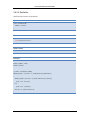
Syntax
public int AI_ReadBulkValue (
BYTE i_byStartCh,
BYTE i_byChTotal,
DWORD i_dwSampleWidth,
Float i_fSampleRate,
DWORD i_dwBufferWidth,
DWORD *o_dwDataBuffer,
OnBulkValueFinishEvent i_CBFunc
)
Parameters
i_byStartCh
[IN] The starting acquire channel
i_byChTotal
[IN] The total channels to acquire
i_dwSampleWidth
[IN] The sampling width (ms)
i_fSampleRate
[IN] The sampling rate (Hz). 10KHz maximum.
i_dwBufferWidth
[IN] The width of the buffer for single channel
*o_dwDataBuffer
[OUT] The 2-dimension buffer array to store
i_CBFunc
[IN] Block operation – NULL
[IN] Non-block operation - The address of callback function.
Return Value
Error code
81
ICP DAS USB Class Members
Example
Int iErrCode
ICPDAS_USBIO m_usbIO;
// To read 0~1 channel for 100ms in 5 KHz sample rate each channel in non-block operation
// So we have the following variable declaration
#define SampleRate 5000
#define BufferWidth 500; // 5000(Hz) * 0.1(100ms)
DWORD m_dwBuffer[2][BufferWidth];
Void BulkFinishCallback(DWORD dwCount)
{
// Callback function to handle data
}
Int main()
{
m_usbIO = new ICPDAS_USBIO();
if(ERR_NO_ERR == (iErrCode = m_usbIO.OpenDevice(USB2019, 1)))
{
if(ERR_NO_ERR != (iErrCode = m_usbIO. AI_ReadBulkValue(0,
2,
100,
SampleRate,
BufferWidth
m_dwBuffer,
BulkFinishCallback)))
printf(“%d”, iErrCode);
while(1) {Sleep(1);}
}
}
82
ICP DAS USB Class Members
5.6.3.13 AI_ReadCJCValue
Analog input function - Read the current CJC value on the module.
Syntax
public int AI_ReadCJCValue (
float *o_fCJCValue
)
Parameters
*o_fCJCValue
[OUT] The CJC value
Return Value
Error code
Example
Int iErrCode
ICPDAS_USBIO m_usbIO;
float o_fCJCValue;
Int iIdx;
m_usbIO = new ICPDAS_USBIO();
if(ERR_NO_ERR == (iErrCode = m_usbIO.OpenDevice(USB2019, 1)))
{
if(ERR_NO_ERR != (iErrCode = m_usbIO.AI_ReadCJCValue(o_fCJCValue)))
printf(“%d”, iErrCode);
else
printf(“%.5f\n”, o_fCJCValue);
}
83
ICP DAS USB Class Members
5.6.3.14 AI_SetTypeCode
The class has two overload methods for setting type code. One provides specifying
channel to set, another for all channel. Please refer to user's manual for analog input
type code. These two overload methods are listed as following table and described in
following section.
Name of Methods
AI_SetTypeCode ( BYTEi_byChToSet, BYTEi_byTypeCode )
AI_SetTypeCode ( BYTE *i_byTypeCodes )
84
ICP DAS USB Class Members
5.6.3.14.1 AI_SetTypeCode (BYTE, BYTE)
Analog input function - Set type code for specific channel. The type code can reference
to Appendix A.1.
Syntax
public int AI_SetTypeCode (
BYTE i_byChToSet,
BYTE i_byTypeCode
)
Parameters
i_byChToSet
[IN] The specific channel to set
i_byTypeCode
[IN] The type code for the specific channel
Return Value
Error code
Example
Int iErrCode
ICPDAS_USBIO m_usbIO;
m_usbIO = new ICPDAS_USBIO();
if(ERR_NO_ERR == (iErrCode = m_usbIO.OpenDevice(USB2019, 1)))
{
if(ERR_NO_ERR != (iErrCode = m_usbIO.AI_SetTypeCode(0, 0x10)))
printf(“%d”, iErrCode);
iErrCode = m_usbIO.CloseDevice();
}
85
ICP DAS USB Class Members
5.6.3.14.2 AI_SetTypeCode (BYTE*)
Analog input function - Set type code for all channels. The type code can reference to
Appendix A.1.
Syntax
public int AI_SetTypeCode (
BYTE *i_byTypeCodes
)
Parameters
*i_byTypeCodes
[IN] The byte array of type code to set
Return Value
Error code
Example
Int iErrCode
ICPDAS_USBIO m_usbIO;
Byte m_byChTypeCode[USBIO_AI_MAX_CHANNEL];
Int iIdx;
m_usbIO = new ICPDAS_USBIO();
if(ERR_NO_ERR == (iErrCode = m_usbIO.OpenDevice(USB2019, 1)))
{
For(iIdx = 0; iIdx < USBIO_AI_MAX_CHANNEL; iIdx)
m_byChTypeCode[iIdx] = 0x10;
if(ERR_NO_ERR != (iErrCode = m_usbIO.AI_SetTypeCode(m_byChTypeCode)))
printf(“%d”, iErrCode);
iErrCode = m_usbIO.CloseDevice();
}
86
ICP DAS USB Class Members
5.6.3.15 AI_SetChCJCOffset
The class has two overload methods for setting channel CJC offset. One provides
specifying channel to set, another for all channel. The valid range of offset is -40.96 ~
+40.95. These two overload methods are listed as following table and described in
following section.
Name of Methods
AI_SetChCJCOffset ( BYTEi_byChToSet, float i_fChCJCOffset )
AI_SetChCJCOffset ( float *i_fChCJCOffsets )
87
ICP DAS USB Class Members
5.6.3.15.1 AI_SetChCJCOffset (BYTE, float)
Analog input function - Set channel CJC offset for specific channel.
Syntax
public int AI_SetTypeCode (
BYTE i_byChToSet,
float i_fChCJCOffset
)
Parameters
i_byChToSet
[IN] The specific channel to set
i_fChCJCOffset
[IN] The CJC offset for the specific channel
Return Value
Error code
Example
Int iErrCode
ICPDAS_USBIO m_usbIO;
m_usbIO = new ICPDAS_USBIO();
if(ERR_NO_ERR == (iErrCode = m_usbIO.OpenDevice(USB2019, 1)))
{
if(ERR_NO_ERR != (iErrCode = m_usbIO.AI_SetChCJCOffset(0, 1.354)))
printf(“%d”, iErrCode);
iErrCode = m_usbIO.CloseDevice();
}
88
ICP DAS USB Class Members
5.6.3.15.2 AI_SetChCJCOffset (float*)
Analog input function - Set channel CJC offset for specific channel.
Syntax
public int AI_SetTypeCode (
float* i_fChCJCOffset
)
Parameters
*i_fChCJCOffset
[IN] The float array of channel CJC offset to set
Return Value
Error code
Example
Int iErrCode
ICPDAS_USBIO m_usbIO;
float m_fChCJCOffset[USBIO_AI_MAX_CHANNEL];
Int iIdx;
m_usbIO = new ICPDAS_USBIO();
if(ERR_NO_ERR == (iErrCode = m_usbIO.OpenDevice(USB2019, 1)))
{
For(iIdx = 0; iIdx < USBIO_AI_MAX_CHANNEL; iIdx)
m_fChCJCOffset[iIdx] = 1.358;
if(ERR_NO_ERR != (iErrCode = m_usbIO.AI_SetChCJCOffset(m_fChCJCOffset)))
printf(“%d”, iErrCode);
iErrCode = m_usbIO.CloseDevice();
}
89
ICP DAS USB Class Members
5.6.3.16 AI_SetChEnable
Analog input function - Set channel enable/disable. Each byte indicates 8 channels
enable/disable mask. Ex: Byte0 -> Channel0 ~ 7
Syntax
public int AI_SetChEnable (
BYTE *i_byChEnable
)
Parameters
*i_byChEnable
[IN] The byte array of channel enable/disable mask
Return Value
Error code
Example
Int iErrCode
ICPDAS_USBIO m_usbIO;
Byte m_byChEnable[(USBIO_AI_MAX_CHANNEL + 7) / 8];
Int iIdx;
m_usbIO = new ICPDAS_USBIO();
if(ERR_NO_ERR == (iErrCode = m_usbIO.OpenDevice(USB2019, 1)))
{
For(iIdx = 0; iIdx <( USBIO_AI_MAX_CHANNEL + 7) / 8; iIdx)
m_byChEnable [iIdx] = 0x5A;
if(ERR_NO_ERR != (iErrCode = m_usbIO.AI_SetChEnable(m_byChEnable)))
printf(“%d”, iErrCode);
iErrCode = m_usbIO.CloseDevice();
}
90
ICP DAS USB Class Members
5.6.3.17 AI_SetFilterRejection
Analog input function - Set filter rejection.
Rejection Setting
Value
60Hz
0
50Hz
1
Syntax
public int AI_SetFilterRejection (
BYTE i_byFilterRejection
)
Parameters
i_byFilterRejection
[IN] The filter rejection
Return Value
Error code
Example
Int iErrCode
ICPDAS_USBIO m_usbIO;
m_usbIO = new ICPDAS_USBIO();
if(ERR_NO_ERR == (iErrCode = m_usbIO.OpenDevice(USB2019, 1)))
{
if(ERR_NO_ERR != (iErrCode = m_usbIO.AI_SetFilterRejection(0)))
printf(“%d”, iErrCode);
iErrCode = m_usbIO.CloseDevice();
}
91
ICP DAS USB Class Members
5.6.3.18 AI_SetCJCOffset
Analog input function - Set CJC offset. The valid range of offset is -40.96 ~ +40.95.
Syntax
public int AI_SetCJCOffset (
float i_fCJCOffset
)
Parameters
i_fCJCOffset
[IN] The CJC offset
Return Value
Error code
Example
Int iErrCode
ICPDAS_USBIO m_usbIO;
m_usbIO = new ICPDAS_USBIO();
if(ERR_NO_ERR == (iErrCode = m_usbIO.OpenDevice(USB2019, 1)))
{
if(ERR_NO_ERR != (iErrCode = m_usbIO.AI_SetCJCOffset(-20.81)))
printf(“%d”, iErrCode);
iErrCode = m_usbIO.CloseDevice();
}
92
ICP DAS USB Class Members
5.6.3.19 AI_SetCJCEnable
Analog input function - Set CJC enable.
Enable Setting
Value
Disable
0
Enable
1
Syntax
public int AI_SetCJCOffset (
BYTE i_byCJCEnable
)
Parameters
i_byCJCEnable
[IN] The CJC enable
Return Value
Error code
Example
Int iErrCode
ICPDAS_USBIO m_usbIO;
m_usbIO = new ICPDAS_USBIO();
if(ERR_NO_ERR == (iErrCode = m_usbIO.OpenDevice(USB2019, 1)))
{
if(ERR_NO_ERR != (iErrCode = m_usbIO.AI_SetCJCEnable(1)))
printf(“%d”, iErrCode);
iErrCode = m_usbIO.CloseDevice();
}
93
ICP DAS USB Class Members
5.6.3.20 AI_SetWireDetectEnable
Analog input function - Set wire detect enable.
Enable Setting
Value
Disable
0
Enable
1
Syntax
public int AI_SetCJCOffset (
BYTE i_byWireDetectEnable
)
Parameters
i_byWireDetectEnable
[IN] The wire detect enable
Return Value
Error code
Example
Int iErrCode
ICPDAS_USBIO m_usbIO;
m_usbIO = new ICPDAS_USBIO();
if(ERR_NO_ERR == (iErrCode = m_usbIO.OpenDevice(USB2019, 1)))
{
if(ERR_NO_ERR != (iErrCode = m_usbIO.AI_SetWireDetectEnable(0)))
printf(“%d”, iErrCode);
iErrCode = m_usbIO.CloseDevice();
}
94
Troubleshooting
6
Troubleshooting
1. Cannot open USB-2K Utility.
USB-2K Utility is written by .NET under .NET Framework 2.0. It is necessary to
have .NET framework 2.0 installed in your computer. The installation package will
check .NET framework 2.0 installed as well or not, and the installer will direct you to
download appropriate file from internet you need. Also, you can use
“FrameworkDetect.exe” to check what versions are installed in your computer. It is
free and public software and can be downloaded from internet easily.
2. Returning timeout error code (65792) after calling set methods or read value.
There are some possible reasons as follow:
USB modules connected to USB hub not local USB port on computer, and
communication timeout is too low to communicate.
(Note: We strong recommended connecting USB modules to local USB port on
computer to prevent unexpected problem.)
Module is failure caused by unknown reason. You can refer to LED indicators
section.
95
Appendix A
Appendix A
A.1 Analog Input Type Code
Code
Input Type
Code
Input Type
0x00
-15 mV ~ +15 mV
0x17
Type L TC, -200 ~ +800°C
0x01
-50 mV ~ + 50 mV
0x18
Type M TC, -200 ~ +100°C
0x02
-100 mV ~ +100 mV
0x19
Type LDIN43710 TC, -200 ~ +900°C
0x03
-500 mV ~ +500 mV
0x1A
0 ~ +20 mA
0x04
-1 V ~ +1 V
0x1B
-150 V ~ +150 V
0x05
-2.5 V ~ +2.5 V
0x1C
-50 V ~ +50 V
0x06
-20 mA ~ +20 mA
0x20
Pt 100, α=.00385, -100 ~ +100°C
0x07
+4 mA ~ +20 mA
0x21
Pt 100, α=.00385, 0 ~ +100°C
0x08
-10 V ~ +10 V
0x22
Pt 100, α=.00385, 0 ~ +200°C
0x09
-5 V ~ +5 V
0x23
Pt 100, α=.00385, 0 ~ +600°C
0x0A
-1 V ~ +1 V
0x24
Pt 100, α=.003916, -100 ~ +100°C
0x0B
-500 mV ~ +500 mV
0x25
Pt 100, α=.003916, 0 ~ +100°C
0x0C
-150 mV ~ +150 mV
0x26
Pt 100, α=.003916, 0 ~ +200°C
0x0D
-20 mA ~ +20 mA
0x27
Pt 100, α=.003916, 0 ~ +600°C
0x0E
Type J TC, -210 ~ +760°C
0x28
Nickel 120, -80 ~ +100°C
0x0F
Type K TC, -210 ~ +1372°C
0x29
Nickel 120, 0 ~ +100°C
0x10
Type T TC, -270 ~ +400°C
0x2A
Pt 1000, α=.00392, -200 ~ +600°C
0x11
Type E TC, -270 ~ +1000°C
0x2B
Cu 100, α=.00421, -20 ~ +150°C
0x12
Type R TC, 0 ~ +1768°C
0x2C
Cu 100, α=.00427, 0 ~ +200°C
0x13
Type S TC, 0 ~ +1768°C
0x2D
Cu 1000, α=.00421, -20 ~ +150°C
0x14
Type B TC, 0 ~ +1820°C
0x2E
Pt 100, α=.00385, -200 ~ +200°C
0x15
Type N TC, -270 ~ +1300°C
0x2F
Pt 100, α=.003916, -200 ~ +200°C
0x16
Type C TC, 0 ~ +2320°C
96
Appendix A
A.2 Analog Output Type Code
Code
Input Type
0x30
0 ~ +20 mA
0x31
0 ~ +20 mA
0x32
0 V ~ +10 V
0x33
-10 V ~ +10 V
0x34
0 V ~ +5 V
0x35
-5 V ~ +5 V
A.3 Pulse Input Type Code
Code
Input Type
0x50
Up counter
0x51
Frequency
0x52
Counter with battery backup
0x53
Encoder
0x54
Up/Down counter
0x55
Pulse/Direction counter
0x56
AB phase
A.4 Channel Status
Code
Input Type
0x00
Good
0x01
Over Range
0x02
Under Range
0x03
Open
0x04
Close
97
Appendix B
Appendix B
B.1 Error Codes
The error codes of class library have three parts of region, device, DEV-library and
IO-library. Each region means different error code returned by device, DEV-library and
IO-library. In the device error code region, it includes basic error and IO related error
codes. And in the DEV-library and IO-library, there are specified error codes defined
what error is to help user debug and program. The error codes are described in the
following table.
Constant/Value
ERR_NO_ERR
0x00000000, 0
ERR_DEV_ILLEGAL_FUNC
0x00000001, 1
ERR_ DEV_ILLEGAL_INDEX
0x00000002, 2
ERR_DEV_ILLEGAL_LENGTH
0x00000003, 3
ERR_DEV_ILLEGAL_PARAMETER
0x00000004, 4
ERR_DEV_ILLEGAL_MAPTABSIZE
0x00000005, 5
ERR_DEV_ILLEGAL_MAPTABINDEX
0x00000006, 6
ERR_ DEV_READONLY
0x00000007, 7
ERR_ DEV_WRITEONLY
0x00000008, 8
ERR_ DEV_BUFFERFULL
0x00000009, 9
ERR_ DEV_LTTIMEOUT
0x0000000A, 10
Description
The operation completed successfully.
The function is invalid.
The index is invalid.
The length is invalid.
The parameter is invalid.
The size of mapping table is invalid.
The index in mapping table is invalid.
The index is read only.
The index is written only.
The buffer in transceiver is full.
The operation of large transfer has timeout.
98
Appendix B
ERR_ DEV_LTMODEFAIL
0x0000000B, 11
ERR_ DEV_LTPKGLOST
0x0000000C, 12
The current mode is not in large transfer mode.
The large transfer packet is lost.
ERR_ DEV_LTINDEXNOTMACH
The offset index is not match while operating in
0x0000000D, 13
large transfer.
ERR_ DEV_LTNOTFINISH
0x0000000E, 14
ERR_DEV_DO_RELATED_ERR
0x00004000~0x000047FFF
ERR_DEV_DI_RELATED_ERR
0x00004800~0x00004FFF
ERR_DEV_AO_RELATED_ERR
0x00005000~0x000057FF
ERR_DEV_AI_RELATED_ERR
0x00005800~0x00005FFF
ERR_DEV_PO_RELATED_ERR
0x00006000~0x000067FF
ERR_DEV_PI_RELATED_ERR
0x00006800~0x00006FFF
ERR_USBDEV_INVALID_DEV
0x00010000, 65536
ERR_USBDEV_DEV_OPENED
0x00010001, 65537
ERR_USBDEV_DEVNOTEXISTS
0x00010002, 65538
ERR_USBDEV_GETDEVINFO
0x00010003, 65539
ERR_USBDEV_ERROR_PKTSIZE
0x00010004, 65540
Another large transfer is operating.
The digital output related error in this region.
The digital input related error in this region.
The analog output related error in this region.
The analog input related error in this region.
The pulse output related error in this region.
The pulse input related error in this region.
The handle of device is invalid.
The device has been opened by class library.
The class library cannot find the device.
An error was made to scan device.
The packet size is invalid.
ERR_USBIO_COMM_TIMEOUT
The communication between computer and
0x00010100, 65792
device has been timeout.
ERR_USBIO_DEV_OPENED
0x00010101, 65793
ERR_USBIO_DEV_NOTOPEN
0x00010102, 65794
ERR_USBIO_INVALID_RESP
The device has been opened by class library.
The device has not opened for operating.
The data returned by device is invalid.
99
Appendix B
0x00010103, 65795
ERR_USBIO_IO_NOTSUPPORT
0x00010104, 65796
ERR_USBIO_PARA_ERROR
0x00010105, 65797
ERR_USBIO_BULKVALUE_ERR
0x00010106, 65798
The method is not supported.
The parameter of method is invalid.
An error occur while getting bulk value.
ERR_USBIO_GETDEVINFO
An error occur while getting device information
0x00010107, 65799
while device opening procedure.
100