1
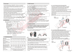
1. Role, purpose
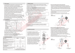
4. Safety mesures
1.1 The electrical in-line, self-controlled diesel fuel heaters with posistor
heating elements are designed to be installed in the cut of the fuel line
just before the fine filter of before the filter-separator, they function at
cruise operating mode (while engine is running).
1.2 The heaters are destined for heating standard European diesel fuel
types (DIN-EN 590 and DIN 51606 ), as well as other types of diesel fuel.
1.3 The heater is installed in the cut of the regular fuel line and connected
to the electrical grid of the vehicle according to the picture 2. The heaters
of PP-200 series have an internal electronic temperature sensor and
a MOSFET temperature control unit. It’s a stand-alone device and
does not need to be controlled or monitored by the driver.
It switches on at the temperature of below + 5°C and switches off at
the temperature of over +5°C .
1.4 The heaters of PP-200 series are universal and can be used on any
type of diesel engines with either 12 or 24 volts electrical circuits and
the maximal fuel flow up to 680 l/h.
1.5 Minimal physical size, light weight and a fixing bracket allows fast and
easy installation of the heater into the engine compartment of any vehicle.
4.1 The installation of PP-200 series heater should be done according
to the general safety rules of automobile electronic equipment installation
and this user manual.
4.2 Only the personnel that had trained and studied its construction
and safety rules shall be admitted to the installation of this device.
4.3 During the installation it is vital to make sure about the thermal
compliance of wires to the ambient operating temperature, the correct core
diameter of wires, to provide reliable cable strapping on each clamp,
to insulate the device form the short circuit and overloading.
2. Completeness
(please, check the completeness for missing or broken parts and,
if any, notify your dealer)
The heater assembled (1)
1 pc.
Wiring kit (2)
1 pc.
Passport, user manuel
1 pc.
Tightening clamps
2 pc.
3. Technical parameters
PP-201
PP-202
PP-203
Power voltage of direct current, V
12±2
24±3
24±3
Nominal power rating, W, at the fuel temperature of:
- 20 °C
+5 °C
220
180
350
300
500
450
Maximal electric current, Àmp, not more then
20
20
25
Threshold fuel temperature for MOSFET trigger, °C
+5 ± 2
Ambient operating temperatures, °C (°F)
from - 40 (-40) till +45 (113)
Maximal fuel flow, liters per hour
150
420
680
Connecting pipe nozzles diameters of input and
output of the fuel, mm
9x1,25
12x1,5
12x1,5
Weight, kg
0,250
0,280
0,270
0,310
0,320
0,370
Working mode
- dried
- with fuel inside
- PROHIBITED to use the device to heat anything else which is not
mentioned in the present user manual;
- PROHIBITED to repair or inspect the device while it is connected
to a live electrical circuit or an alternator of a working engine;
- PROHIBITED to activate the device while there is no fuel in the fuel line,
or if the fuel line contains air bubbles;
- PROHIBITED to activate the device on air or without proper installation
into the fuel system of an engine.
4.5 During the installation or de-installation it is important to comply
to the safety measure related to the diesel fuel spills, ensuring the maximal
occupational hygiene.
(1) - consists of the body of the heater with wiring kit (wire N°1 S=2,5 mm≤ – red,
N°2 S=2,5 mm≤ –black, thermal insulation of wires: up to + 125 °C), AMP connector.
The heater type is mentioned on the package.
(2) – manual control wiring kit for connecting to the vehicle electrical grid:
on-off switcher, relay, LED indicator, fuse 20À, wires: (wire N°1 S=0,75 mm≤ – blue,
N°2 S=0,75 mm≤ – red , N°3 S=0,75 mm≤ – yellow, N°4 S=2,5 mm≤ – thick red,
N°5 S=2,5 mm≤ – black, thermal insulation of wires: up to + 125 °C),
AMP connector, LED indicator, fuse 20À.
Index name
4.4 To ensure the safety measures it is PROHIBITED
- to use the device in engines running on petrol or on mixture of
diesel and petrol.
cruise operating mode,
powered by the vehicle's alternator
5. Installation procedure
5.1 ATTENTION ! Installation should be executed either at the special
service centers or maintenance facilities that can provide skilled personnel
in the domain of electronic equipment installation for cars and trucks.
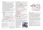
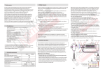
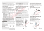
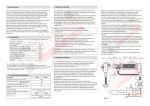
5.2 The heater is installed in the cut of the regular fuel line and connected
to the electrical circuit of the vehicle according to the picture 2.
The fuel input direction is indicated on the input pipe with an arrow.
Working position of the heater - vertical. The input and output pipes must
be horizontal, see the picture 1.
5.3 The exact position of the heater
in the engine compartment differs
depending on the vehicle model,
but it must be in the cut of the fuel
line just before and as close as
possible to the fuel filter or filterseparator.
The maximal declination of the filter
from the vertical position must not
exceed 10-15°.
5.4 Electrical connections of
the heater are done according to
the layout on the picture 2.
Pic. 1
Pic. 2
6. Function guideline
6.1 The PP-200 heater is a stand-alone device and functions in
self-controlling mode. Once the ignition contact is on and the engine
is running, the heater starts measuring the input temperature of the fuel
using its internal sensor. If the temperature is lower than +5°Ñ the heater
is activated, when the fuel temperature exceeds +5°Ñ the heating is
desactivated. The heater's activation is confirmed by the LED indicator
in the driver's cabin.
6.2 The heating always stops when the ignition key is off.
6.3 While the usage the heater must always be filled with fuel.
If a vehicle with this heater installed was not used for a long period
of time, it is recommended to make sure that the fuel line is not dried
before starting the engine. In case of doubts it is recommended to
disconnect the heater from the electrical circuit and start the engine
until it becomes absolutely clear that the fuel line is filled with fuel.
6.4 It is recommended to clean the heater from inside at each yearly
maintenance by removing it from the fuel line and cleaning it with a
flow of diesel fuel through the input.
6.5 It is recommended to verify at each maintenance session the fixing
point of the heater in the engine compartment, the absence of the fuel
leaks and the tightness of the electrical contacts and nozzle clamps.
6.6 The body of PP-200 is sealed and is not designed to be opened
and repaired if malfunctioned. If malfunction occurs during the warranty
time the device can be replaced through the local dealer, on the condition
of complying with warranty terms.
Manufacturer: ALC «NOMACON»
Minsk, Kozlova lane 7a
220037, Republic of Belarus
Tel/Fax: +375 17 299-54-85
7. Storage, disposal
7.1 When stored or transported to the installation facilities the heater must be
properly packed in the package provided by the manufacturer or the dealer.
7.2 The PP-200 series heaters do not contain any substances that are harmful
in any way to the environment or to a human body.
8. Content of precious and non-ferrous metals
8.1 Precious metals: not present.
8.2 Non-ferrous metals: – aluminium – 12g (PP-201, PP-202) – 16g (PP 203),
– copper – 0,35 g, tin – 1,5 g
9. Warranty
9.1 The manufacturer guarantees the adequacy of the PP-200 series
heaters to the description in the present reference documentation if
complied with the conditions of storage, transport, installation and usage.
9.2 Storage period – 2 years from the manufacturing date.
9.3 Usage warranty – 18 months from the date of purchase or from
the date of manufacture if the purchase date is not known.
9.4 During the warranty period the consumer has a right to replace the
malfunctioned heater by sending back all pieces of it to the local dealer with
the copy of the purchase invoice. Postage costs are not refunded to the
consumer. (It is recommended to include a short description in English
language concerning the circumstances of the malfunction).
The local dealer in its turn will send the new heater to the consumer.
9.5 Warranty claim will be refused if:
- the malfunctioned device is not sent or delivered to the local dealer;
- the malfunctioned device is sent without a proof of purchase such as
purchase invoice;
- the device is sent with some of its pieces missing (no cables or band clips);
- the device has mechanical damage or scratches that do not normally
occur during its usage. For example after a road accident;
- any indications of non-compliance with the conditions of storage,
transport, installation and usage are the reasons for the warranty
claim refusal.
ISO 9001 : 2008
DE-496413 QM08
Official Dealer in Europe:
Argus Graphic sprl
Av des Croix du Feu 31
1020 Brussels, Belgium
VAT: BE 0898.543.563
E-mail: [email protected]
Tel.: + 32 484 755 758
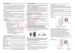
IN-LINE
DIESEL FUEL HEATERS
NOMACON™ PP-200 series
PP-201 (12V)
PP-202 (24V)
PP-203 (24V)
USER MANUAL