1
INSTALLATIONS
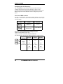
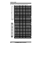
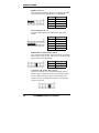
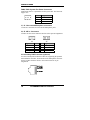
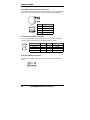
J16: USB and Primary RJ45 Connectors
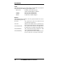
J16 consists of the primary RJ-45 connector (top) and two stacked USB
ports. Refer to the section below for their respective pin assignments.
USB1
USB2
Pin #
1
2
3
4
Signal Name
Vcc
USBUSB+
Ground
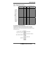
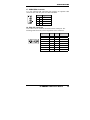
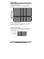
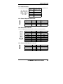
J17: Smart Card Reader Interface
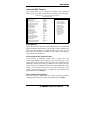
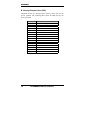
J17 is a 14-pin header that provides interface for a Smart Card Reader.
The table below shows the pin assignments of this pin header.
Signal Name
Vcc
-SCRFET
SCRCLK
Ground
Pin #
1
3
5
7
Pin #
2
4
6
8
Signal Name
No connect
SCRRST
SCRIO
-SCRPRES
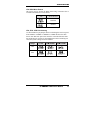
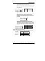
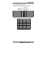
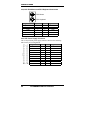
J18: +5V Standby Connector
J18 is the +5V standby 2-pin connector. Refer to the pin assignments
below.
22
TL-EMBSBC 815E User’s Manual