1
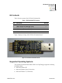
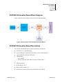
Z8051™ Family of 8-Bit Microcontrollers Z51F0410 Evaluation Kit User Manual UM025703-1212 Copyright ©2012 Zilog®, Inc. All rights reserved. www.zilog.com Z51F0410 Evaluation Kit User Manual ii Warning: DO NOT USE THIS PRODUCT IN LIFE SUPPORT SYSTEMS. LIFE SUPPORT POLICY ZILOG’S PRODUCTS ARE NOT AUTHORIZED FOR USE AS CRITICAL COMPONENTS IN LIFE SUPPORT DEVICES OR SYSTEMS WITHOUT THE EXPRESS PRIOR WRITTEN APPROVAL OF THE PRESIDENT AND GENERAL COUNSEL OF ZILOG CORPORATION. As used herein Life support devices or systems are devices which (a) are intended for surgical implant into the body, or (b) support or sustain life and whose failure to perform when properly used in accordance with instructions for use provided in the labeling can be reasonably expected to result in a significant injury to the user. A critical component is any component in a life support device or system whose failure to perform can be reasonably expected to cause the failure of the life support device or system or to affect its safety or effectiveness. Document Disclaimer ©2012 Zilog, Inc. All rights reserved. Information in this publication concerning the devices, applications, or technology described is intended to suggest possible uses and may be superseded. ZILOG, INC. DOES NOT ASSUME LIABILITY FOR OR PROVIDE A REPRESENTATION OF ACCURACY OF THE INFORMATION, DEVICES, OR TECHNOLOGY DESCRIBED IN THIS DOCUMENT. ZILOG ALSO DOES NOT ASSUME LIABILITY FOR INTELLECTUAL PROPERTY INFRINGEMENT RELATED IN ANY MANNER TO USE OF INFORMATION, DEVICES, OR TECHNOLOGY DESCRIBED HEREIN OR OTHERWISE. The information contained within this document has been verified according to the general principles of electrical and mechanical engineering. Z8051 is a trademark or registered trademark of Zilog, Inc. All other product or service names are the property of their respective owners. UM025703-1212 Z51F0410 Evaluation Kit User Manual iii Revision History Each instance in the Revision History table below reflects a change to this document from its previous version. Revision Level Description Page Dec 2012 03 Corrected Figures 5 and 7. 7,9 Dec 2012 02 Corrected formatting issue in Table 2. 16 Nov 2012 01 Original issue. All Date UM025703-1212 Revision History Z51F0410 Evaluation Kit User Manual iv Table of Contents Revision History . . . . . . . . . . . . . . . . . . . . . . . . . . . . . . . . . . . . . . . . . . . . . . . . . . . . . . . . . . . . .iii List of Figures . . . . . . . . . . . . . . . . . . . . . . . . . . . . . . . . . . . . . . . . . . . . . . . . . . . . . . . . . . . . . . . v List of Tables. . . . . . . . . . . . . . . . . . . . . . . . . . . . . . . . . . . . . . . . . . . . . . . . . . . . . . . . . . . . . . . vii Introduction . . . . . . . . . . . . . . . . . . . . . . . . . . . . . . . . . . . . . . . . . . . . . . . . . . . . . . . . . . . . . . . . . 1 Install the Z8051 OCD Software and Documentation . . . . . . . . . . . . . . . . . . . . . . . . . . . . . . . . 5 Configure the Z8051 OCD and Z51F0410 Evaluation Board . . . . . . . . . . . . . . . . . . . . . . . . . 15 Build and Run the Z51F0410 Demo Project. . . . . . . . . . . . . . . . . . . . . . . . . . . . . . . . . . . . . . . 18 Sample Projects and Documentation . . . . . . . . . . . . . . . . . . . . . . . . . . . . . . . . . . . . . . . . . . . . 36 Appendix A. Schematic Diagrams . . . . . . . . . . . . . . . . . . . . . . . . . . . . . . . . . . . . . . . . . . . . . . 37 Appendix B. OCD Driver Installation on Windows Vista Systems . . . . . . . . . . . . . . . . . . . . . 39 Appendix C. OCD Driver Installation on Windows XP Systems. . . . . . . . . . . . . . . . . . . . . . . 42 Appendix D. Stand-Alone Flash Programming Using the Keil µVision IDE . . . . . . . . . . . . . 45 Customer Support . . . . . . . . . . . . . . . . . . . . . . . . . . . . . . . . . . . . . . . . . . . . . . . . . . . . . . . . . . . 47 UM025703-1212 Table of Contents Z51F0410 Evaluation Kit User Manual v List of Figures Figure 1. The Z51F0410 Evaluation Kit . . . . . . . . . . . . . . . . . . . . . . . . . . . . . . . . . . . . 1 Figure 2. Z51F0410 Evaluation Board . . . . . . . . . . . . . . . . . . . . . . . . . . . . . . . . . . . . . 2 Figure 3. Block Diagram of the Z51F0410 Evaluation Board . . . . . . . . . . . . . . . . . . . 3 Figure 4. Install Device Driver Dialog, Windows 7 . . . . . . . . . . . . . . . . . . . . . . . . . . . 6 Figure 5. Browse For Driver Dialog, Windows Vista . . . . . . . . . . . . . . . . . . . . . . . . . . 7 Figure 6. Can’t Verify Publisher Dialog, Windows Vista . . . . . . . . . . . . . . . . . . . . . . 8 Figure 7. Successfully Installed Dialog, Windows Vista . . . . . . . . . . . . . . . . . . . . . . . 9 Figure 8. Unsuccessful Installation, Scenario 1 . . . . . . . . . . . . . . . . . . . . . . . . . . . . . 10 Figure 9. Unsuccessful Installation, Scenario 2 . . . . . . . . . . . . . . . . . . . . . . . . . . . . . 11 Figure 10. Device Manager Dialog, Windows 7 . . . . . . . . . . . . . . . . . . . . . . . . . . . . . . 12 Figure 11. A Successful USB-to-UART Driver Installation . . . . . . . . . . . . . . . . . . . . . 14 Figure 12. Connecting the 10-Circuit Cable to the Board . . . . . . . . . . . . . . . . . . . . . . . 15 Figure 13. Connecting the Evaluation Board's P1 Port to the USB Port . . . . . . . . . . . 16 Figure 14. An Example Setup . . . . . . . . . . . . . . . . . . . . . . . . . . . . . . . . . . . . . . . . . . . . 17 Figure 15. Initial OCD Screen . . . . . . . . . . . . . . . . . . . . . . . . . . . . . . . . . . . . . . . . . . . . 19 Figure 16. Object File Dialog . . . . . . . . . . . . . . . . . . . . . . . . . . . . . . . . . . . . . . . . . . . . 20 Figure 17. Configuration Dialog . . . . . . . . . . . . . . . . . . . . . . . . . . . . . . . . . . . . . . . . . . 21 Figure 18. A Typical On-Chip Debugger Window . . . . . . . . . . . . . . . . . . . . . . . . . . . . 22 Figure 19. A Typical On-Chip Debugger with Child Windows Open . . . . . . . . . . . . . 23 Figure 20. Reset Toolbar Icon . . . . . . . . . . . . . . . . . . . . . . . . . . . . . . . . . . . . . . . . . . . . 23 Figure 21. HyperTerminal Message After Selecting Go . . . . . . . . . . . . . . . . . . . . . . . . 24 Figure 22. Z51F0410 Demo Program . . . . . . . . . . . . . . . . . . . . . . . . . . . . . . . . . . . . . . 25 Figure 23. Selecting the Demo Project File . . . . . . . . . . . . . . . . . . . . . . . . . . . . . . . . . 27 Figure 24. Selecting the Target . . . . . . . . . . . . . . . . . . . . . . . . . . . . . . . . . . . . . . . . . . . 28 Figure 25. Selecting the Target Driver . . . . . . . . . . . . . . . . . . . . . . . . . . . . . . . . . . . . . 29 Figure 26. Configuring the Debug Options . . . . . . . . . . . . . . . . . . . . . . . . . . . . . . . . . . 30 Figure 27. Configuring the Flash Options . . . . . . . . . . . . . . . . . . . . . . . . . . . . . . . . . . . 31 Figure 28. Load Application at Startup Settings . . . . . . . . . . . . . . . . . . . . . . . . . . . . . . 31 UM025703-1212 List of Figures Z51F0410 Evaluation Kit User Manual vi Figure 29. Beginning a Debug Session . . . . . . . . . . . . . . . . . . . . . . . . . . . . . . . . . . . . . 32 Figure 30. A Default Debug Session . . . . . . . . . . . . . . . . . . . . . . . . . . . . . . . . . . . . . . . 32 Figure 31. Demo Program Menu in HyperTerminal . . . . . . . . . . . . . . . . . . . . . . . . . . . 35 Figure 32. Z51F0410 Evaluation Board, #1 of 2 . . . . . . . . . . . . . . . . . . . . . . . . . . . . . 37 Figure 33. Z51F0410 Evaluation Board, #2 of 2 . . . . . . . . . . . . . . . . . . . . . . . . . . . . . 38 Figure 34. Found New Hardware Dialog, Windows Vista . . . . . . . . . . . . . . . . . . . . . . 39 Figure 35. Install Device Driver Dialog, Windows Vista . . . . . . . . . . . . . . . . . . . . . . . 40 Figure 36. Couldn’t Find Driver Dialog, Windows Vista . . . . . . . . . . . . . . . . . . . . . . . 41 Figure 37. The Found New Hardware Wizard Welcome Screen . . . . . . . . . . . . . . . . . 42 Figure 38. The Found New Hardware Wizard’s Browse Screen . . . . . . . . . . . . . . . . . 43 Figure 39. Selecting A Target Driver For Flash Programming . . . . . . . . . . . . . . . . . . . 45 Figure 40. Configuring Additional Flash Options . . . . . . . . . . . . . . . . . . . . . . . . . . . . 46 Figure 41. The Keil IDE Flash Menu . . . . . . . . . . . . . . . . . . . . . . . . . . . . . . . . . . . . . . 46 UM025703-1212 List of Figures Z51F0410 Evaluation Kit User Manual vii List of Tables Table 1. Z51F0410000KITG Contents . . . . . . . . . . . . . . . . . . . . . . . . . . . . . . . . . . . . 2 Table 2. Jumper Settings . . . . . . . . . . . . . . . . . . . . . . . . . . . . . . . . . . . . . . . . . . . . . . 16 Table 3. Z51F0410 Evaluation Kit Sample Projects . . . . . . . . . . . . . . . . . . . . . . . . . 36 Table 4. Z51F0410 Evaluation Kit Documentation . . . . . . . . . . . . . . . . . . . . . . . . . . 36 UM025703-1212 List of Tables Z51F0410 Evaluation Kit User Manual 1 Introduction This manual describes how to set up Zilog’s Z51F0410 Evaluation Kit (Zilog part number Z51F0410000KITG) and use it to evaluate your Z8051-based designs and applications. The Kit features a small Evaluation Board consisting of two LEDs, two pushbuttons, port pin headers and a USB port. The Board features the Z51F0410 MCU in a 10-pin SSOP package, plus a DBG connector to connect the board to a host development PC using the Z8051 USB On-Chip Debugger (OCD) cable. For more details about the Z51F0410 MCU, please refer to the Z51F0410 Product Specification (PS0295). This document guides you through the following tasks: • • • Install the Z8051 OCD Software and Documentation – see page 5 Configure the Z8051 OCD and Z51F0410 Evaluation Board – see page 15 Build and Run the Z51F0410 Demo Project – see page 18 Figure 1 displays an image of the Z51F0410 Evaluation Kit. Figure 1. The Z51F0410 Evaluation Kit UM025703-1212 Introduction Z51F0410 Evaluation Kit User Manual 2 Kit Contents Table 1 lists the contents of the Z51F0410 Evaluation Kit. Table 1. Z51F0410000KITG Contents Item Description Quantity 1 Z51F0410 Evaluation Board 1 2 Z8051 USB On-Chip Debugger (OCD) 1 3 Z8051 OCD Target Cable (10ckt) 1 4 USB Cable: A (male) to Mini-B 1 5 Z51F0410 Evaluation Kit Insert (FL0148) 1 Figure 2 displays an image of the Z51F0410 Evaluation Board. Figure 2. Z51F0410 Evaluation Board Supported Operating Systems The Z51F0410 Evaluation Board and the Z8051 On-Chip Debugger support the following operating systems: • • • UM025703-1212 Microsoft Windows XP Microsoft Windows Vista (32-bit/64-bit) Microsoft Windows 7 (32-bit/64-bit) Introduction Z51F0410 Evaluation Kit User Manual 3 Z51F0410 Evaluation Board Block Diagram Figure 3 displays a block diagram of the Z51F0410 Evaluation Board. Figure 3. Block Diagram of the Z51F0410 Evaluation Board Z51F0410 Evaluation Board Description The Z51F0410 Evaluation Board contains the following components: • • • • Z51F0410: U2, 10-pin SSOP chip • • • • USB connector: P1 UM025703-1212 1 green LED (D2) is connected to the GPIO pin of the Z51F0410 MCU 1 green LED (D1) to indicate USB power 2 pushbuttons: – SW1: RESET – SW2 is connected to the GPIO pin on the Z51F0410 MCU OCD connector: J4, J3 USB to UART interface: U1 USB interface provides power and communication to the Board Introduction Z51F0410 Evaluation Kit User Manual 4 • Test points J1 and J2 are connected to Ground; J7–J14 are connected to GPIO pin of U2 When the Board is connected to the USB port of the host PC, the green D1 LED will illuminate (turn ON). Schematic diagrams of the Z51F0410 Evaluation Board are presented on pages 37 through 38 of this document. The physical dimensions of the Board are: 1.75" x 0.75" (44.4 mm x 19 mm). UM025703-1212 Introduction Z51F0410 Evaluation Kit User Manual 5 Install the Z8051 OCD Software and Documentation The Z8051 On-Chip Debugger (OCD) interface is the interface by which your PC will communicate with the Z51F0410 MCU to download and execute code. In addition to the OCD, software such as development tools and sample applications will be installed. Supported Operating Systems The Software and Documentation for this reference design supports Microsoft Windows 7 (32-bit/64-bit), Windows Vista (32-bit/64-bit) and Windows XP. Note: If you have already downloaded the Z8051 software and documentation from the Zilog Store and installed it following the procedure on the paper insert in your kit (FL0148), skip this section and proceed to the Z8051 OCD Driver Installation section, below. Observe the following procedure to install the Z8051 On-Chip Debugger software and documentation on your computer. 1. Ensure that the OCD interface hardware is not connected to your PC. 2. In a web browser, download the Z8051 Software and Documentation v2.1 or later from the Zilog Store. When the download is complete, unzip the file to your hard drive and double-click to launch the installation file named Z8051_<version>.exe. 3. From the main menu, select Go to the installation page, then select one of the following options: – If you do not plan to use the Keil µVision4 IDE, select Zilog OCD + Samples + SDCC. – If you will be using the Keil µVision4 IDE, select Zilog OCD + Samples + Keil µVision4 IDE Debugging Support. – If you only plan to use the programming features and do not plan to perform any development, select Zilog OCD. – To install all files, select All of the above. Note: In this filename, <version_number> refers to the version number of the OCD Software and Documentation release. For example, this version number may be 2.1. UM025703-1212 Install the Z8051 OCD Software and Documentation Z51F0410 Evaluation Kit User Manual 6 4. Follow the on-screen instructions to complete the OCD software installation. Z8051 OCD Driver Installation The driver programs for the Z8051 On-Chip Debugger are copied during the software and documentation installation. In the following procedure for PCs running Windows 7 32and 64-bit operating systems, ensure that the target side of the OCD will remain unconnected while you install these drivers. Note: If you are running Windows Vista, see Appendix B. on page 39 to install your device drivers. If you are running Windows XP, see Appendix C. on page 42. 1. Connect the OCD hardware to the USB port of your PC by connecting the A (male) end of the USB A (male)-to-Mini-B cable with the host PC’s USB port. Connect the Mini-B end to the OCD device. 2. After the PC detects the new hardware, it will display the Installing device driver software dialog shown in Figure 4. Figure 4. Install Device Driver Dialog, Windows 7 IMPORTANT NOTE: If you should encounter the scenarios presented in Figures 8 or 9, right-click your mouse on ZILOG OCD I/F (highlighted in Figure 8) or Unknown device (highlighted in Figure 9) and select Update Driver Software... 3. Select Browse my computer for driver software (advanced) to display the dialog shown in Figure 5, which prompts you to key in or browse for the location of the .inf file. Depending on the type of computer you use (32- bit or 64-bit), use the Browse button to navigate to one of the following paths, then click the Next button. – On 32-bit machines, use the following path: <Z8051 Installation>\Z8051_<version_number>\device drivers\OCD USB\x32 UM025703-1212 Install the Z8051 OCD Software and Documentation Z51F0410 Evaluation Kit User Manual 7 – On 64-bit machines, use the following path: <Z8051 Installation>\Z8051_<version_number>\device drivers\OCD USB\x64 Note: In the above filepaths, <Z8051 Installation> refers to C:\Program Files\zilog. Figure 5. Browse For Driver Dialog, Windows Vista UM025703-1212 Install the Z8051 OCD Software and Documentation Z51F0410 Evaluation Kit User Manual 8 4. When Windows prompts you whether to install or not install, as shown in Figure 6, click Install this driver software anyway and wait until the installation is completed (Windows may prompt you more than once). Figure 6. Can’t Verify Publisher Dialog, Windows Vista UM025703-1212 Install the Z8051 OCD Software and Documentation Z51F0410 Evaluation Kit User Manual 9 5. When the installation is complete, the screen shown in Figure 7 will appear. Click Close to exit the OCD driver installation. Figure 7. Successfully Installed Dialog, Windows Vista Note: On some installations, the Found New Hardware screen shown in Figure 7 may also display the text string, Zilog Z8051 USB OCD - No Firmware. This occurrence is normal and can be disregarded. UM025703-1212 Install the Z8051 OCD Software and Documentation Z51F0410 Evaluation Kit User Manual 10 Figure 8. Unsuccessful Installation, Scenario 1 UM025703-1212 Install the Z8051 OCD Software and Documentation Z51F0410 Evaluation Kit User Manual 11 Figure 9. Unsuccessful Installation, Scenario 2 UM025703-1212 Install the Z8051 OCD Software and Documentation Z51F0410 Evaluation Kit User Manual 12 6. If Zilog Z8051 USB OCD appears in the Device Manager (as highlighted in Figure 10), the OCD driver software has been successfully installed. Figure 10. Device Manager Dialog, Windows 7 UM025703-1212 Install the Z8051 OCD Software and Documentation Z51F0410 Evaluation Kit User Manual 13 FTDI USB-to-UART Driver Installation An FTDI USB-to-UART driver is required to allow your PC to communicate through its USB port to the on-chip UART of the Z51F0410 MCU. Observe the following procedure to perform these connections. 1. Ensure that the Z51F0410 Evaluation Board’s P1 connector is not plugged in to the host PC’s USB port. 2. Navigate to the following filepath and double-click the CDM20802_setup.exe file to begin the driver installation. <Z8051 Installation>\Z8051_<version_number>\device drivers\FTDI Uart 3. The installation process will begin and you should observe output similar to the following messages on the screen of your PC: 32-bit OS detected <installation path>\dpinstx86.exe Installation driver FTDI CDM driver installation process completed. Note: The above message may appear for a short time, but will then disappear from your window. This occurrence is normal. 4. When the installation is complete, plug in the Board’s P1 connector into the USB port of your PC. Refer to Figure 13 on page 16 for guidance. 5. If the driver installation was successful, the Ports (COM & LPT) section of the Device Manager will display USB Serial Port (COMx) or similar message, as highlighted in Figure 11. UM025703-1212 Install the Z8051 OCD Software and Documentation Z51F0410 Evaluation Kit User Manual 14 Figure 11. A Successful USB-to-UART Driver Installation Note: 1. To launch the Device Manager on Windows 7 systems, launch the Start menu, enter device manager in the Search programs and files field, and press the Enter key. 2. To open the Device manager on earlier Windows systems, navigate via the following path: Start → Control Panel → System → Hardware → Device Manager → Ports (COM& LPT) UM025703-1212 Install the Z8051 OCD Software and Documentation Z51F0410 Evaluation Kit User Manual 15 Configure the Z8051 OCD and Z51F0410 Evaluation Board Observe the following procedure to set up and configure the Z8051 On-Chip Debugger and the Z51F0410 Board. Caution: Steps number 1 to 4 present the power-up sequence. Carefully follow these steps to avoid encountering an improper connection or disconnection. 1. Connect the Z8051 On-Chip Debugger (OCD) to the host PC’s USB port. 2. Connect one end of the 10-circuit cable to the Z8051 OCD. 3. Connect the other end of the 10-circuit cable connector to the Z51F0410 Board’s J4 and J3 connectors. Pin 1 of the cable connector is indicated by a red stripe, as shown in Figure 12. Figure 12. Connecting the 10-Circuit Cable to the Board 4. Set the jumpers as indicated in Table 2. UM025703-1212 Configure the Z8051 OCD and Z51F0410 Evaluation Z51F0410 Evaluation Kit User Manual 16 Table 2. Jumper Settings Jumper Description TxD J5 RxD J6 D2 LED State Function Factory Setting 1–2 TxD_0 IN 3–4 TxD_1 5–6 RxD_0 7–8 RxD_1 1–2 DSDA 2–3 RxD_1 IN IN 5. Connect P1 on the Z51F0410 Board to the host PC’s USB port to apply power to the Board, as shown in Figure 13. Notes: 1. Upon applying power, the green LED (D1) will be illuminated. 2. When recycling power, Zilog recommends waiting for at least 5 seconds before reapplying power to allow a proper power-on reset. Figure 13. Connecting the Evaluation Board's P1 Port to the USB Port UM025703-1212 Configure the Z8051 OCD and Z51F0410 Evaluation Z51F0410 Evaluation Kit User Manual 17 Figure 14 shows an example of a completed hardware and software setup. Figure 14. An Example Setup UM025703-1212 Configure the Z8051 OCD and Z51F0410 Evaluation Z51F0410 Evaluation Kit User Manual 18 Build and Run the Z51F0410 Demo Project Observe the following procedure to build and run the Z51F0410 demo project. Note: If you plan to use the Keil µVision IDE, please skip to the Using the Keil µVision IDE on a Demo Project section on page 25. 1. Browse to the following location and double-click the build_sdcc.bat batch file to build the project: <Z8051 Installation>\Z8051_<version_number>\samples\Z51F0410\Demo\build_sdcc.bat Note: Refer to the Z8051 Tools Product User Guide (PUG0033) for additional information about these project files and Small Device C Compiler (SDCC) development tools. 2. When the build is complete, the command window will prompt the user to press any key to continue. Proceed by pressing any key on your keyboard; as a result, a hex file for the demo will be created in the following path: <Z8051 Installation>\Z8051_<version_number>\samples\Z51F0410\Demo\demo.hex 3. Set up the OCD and Evaluation Board. If you have not already configured these items, please return to the Configure the Z8051 OCD and Z51F0410 Evaluation Board section on page 15. 4. Run the Z8051 OCD software. From the Start menu, navigate to All Programs → Zilog Z8051 SW and Docs <version_number> → Zilog Z8051 OCD <version_number>. Once launched, the program will display Connected, as shown in Figure 15. Note: If you encounter a message that says Disconnected, return to the Configure the Z8051 OCD and Z51F0410 Evaluation Board section on page 15 to configure the proper powerup sequence. If the problem persists, Zilog recommends that you review the Z8051 OCD Driver Installation and FTDI USB-to-UART Driver Installation sections. UM025703-1212 Build and Run the Z51F0410 Demo Project Z51F0410 Evaluation Kit User Manual 19 Figure 15. Initial OCD Screen Note: For a free download of the latest version of the OCD software, visit the Zilog website and navigate via the Tools and Software menu to Software Downloads. 5. In the Debugger window, select Load Hex from the File menu to display the Object File dialog, which is shown in Figure 16. UM025703-1212 Build and Run the Z51F0410 Demo Project Z51F0410 Evaluation Kit User Manual 20 Figure 16. Object File Dialog 6. In the Object file dialog, browse to the hex file that you created in Step 2 and click Open. 7. Click the Download button to open the Configuration dialog box, shown in Figure 17. UM025703-1212 Build and Run the Z51F0410 Demo Project Z51F0410 Evaluation Kit User Manual 21 Figure 17. Configuration Dialog 8. Click the Write button to open the On-Chip Debugger’s main window. A typical OCD display is shown in Figure 18; Figure 19 shows an OCD window with child windows open. UM025703-1212 Build and Run the Z51F0410 Demo Project Z51F0410 Evaluation Kit User Manual 22 Figure 18. A Typical On-Chip Debugger Window UM025703-1212 Build and Run the Z51F0410 Demo Project Z51F0410 Evaluation Kit User Manual 23 Figure 19. A Typical On-Chip Debugger with Child Windows Open Note: Use the View menu to open the child windows. For this demonstration, the example windows shown in Figure 19 do not need to be opened. 9. Click the Reset toolbar icon of the OCD software, which is shown in Figure 20. Figure 20. Reset Toolbar Icon 10. Open HyperTerminal. Next, select the appropriate COM port and set it to 9600 8-N-1. 11. From the Emulation menu of the OCD software, select Go. As a result, you should see the HyperTerminal message shown in Figure 21. UM025703-1212 Build and Run the Z51F0410 Demo Project Z51F0410 Evaluation Kit User Manual 24 Figure 21. HyperTerminal Message After Selecting Go 12. Disconnect the OCD 10-ckt cable from the Evaluation Board. 13. Unplug the Evaluation Board from the PC. 14. Disconnect the HyperTerminal connection. 15. Plug the Evaluation Board into the PC’s USB port. 16. Reestablish a HyperTerminal connection by clicking the Call button. 17. Press any key on the active HyperTerminal window; see Figure 22. UM025703-1212 Build and Run the Z51F0410 Demo Project Z51F0410 Evaluation Kit User Manual 25 Figure 22. Z51F0410 Demo Program 18. Press SW2 on the Evaluation Board, or key in a 1 in the active HyperTerminal window to start/stop the blinking of LED D2. Note: Similar projects that you can use as references are listed in Table 3 on page 36. Using the Keil µVision IDE on a Demo Project Zilog’s On-Chip Debugger hardware now fully supports the Keil µVision IDE. Our target driver is seamlessly integrated with the Keil debugger, allowing Keil C51 users to work within the µVision4 environment without switching between the Keil compiler and Zilog’s external OCD software. In the demo project example that follows, the Z51F0410 MCU-related project is referenced as Demo. UM025703-1212 Build and Run the Z51F0410 Demo Project Z51F0410 Evaluation Kit User Manual 26 Notes: 1. This document refers to the Keil µVision IDE V4.53.0.6 (PK51 Prof. Developers Kit) or later. 2. Refer to the Z8051 Tools Product User Guide (PUG0033) for additional information about these project files and debugging with the Keil µVision IDE and Zilog On-Chip Debugger. Debugger Configuration Observe the following procedure to build and run a Z51F0410 demonstration project using the Keil µVision IDE. 1. Start the Keil µVsion4 IDE. 2. From the Project menu, select Open Project and navigate to the following filepath: <Installation directory>\Z8051_<version>\samples\Z51F0410\Demo 3. Select the Demo.uvproj file and click Open; see Figure 23. UM025703-1212 Build and Run the Z51F0410 Demo Project Z51F0410 Evaluation Kit User Manual 27 Figure 23. Selecting the Demo Project File 4. Return to the Project menu and select Options for Target ‘Demo’. 5. In the Options for Target ‘Demo’ dialog that appears, click the Device tab and ensure that your target is properly selected for your project, as illustrated in Figure 24. UM025703-1212 Build and Run the Z51F0410 Demo Project Z51F0410 Evaluation Kit User Manual 28 Figure 24. Selecting the Target 6. After selecting the target, click the Debug tab and select the Zilog Z8051 Target Driver from the Use: drop-down menu, as highlighted in Figure 25. UM025703-1212 Build and Run the Z51F0410 Demo Project Z51F0410 Evaluation Kit User Manual 29 Figure 25. Selecting the Target Driver 7. Click the Settings button, located to the right of this drop-down menu, to configure your Debug and Flash options. The Settings dialog is displayed with the Debug Options tab appearing by default, as shown in Figure 26. UM025703-1212 Build and Run the Z51F0410 Demo Project Z51F0410 Evaluation Kit User Manual 30 Figure 26. Configuring the Debug Options Notes: 1. When configuring the appropriate Debug option, be aware of the following stipulations: • Checking the Peripheral continues running option means that the timers used in your project will run while the processor is stopped by the debugger. • The Reset at Main option will only work if you have a main file in your project; otherwise you should deselect this option. 2. 3. Click the Flash Options tab. The Flash Options Settings dialog will appear, as shown in Figure 27. To select the proper options for Flash programming, refer to the Z51F0410 Product Specification (PS0295). UM025703-1212 Build and Run the Z51F0410 Demo Project Z51F0410 Evaluation Kit User Manual 31 Figure 27. Configuring the Flash Options 4. Click OK to exit the Settings dialog. 5. From the Options for Target ‘Demo’ dialog, select the Load Application at Startup checkbox, as shown in Figure 28, the so that the IDE will download the code upon connection. There is no need to select or enter an initialization file. Figure 28. Load Application at Startup Settings 6. Click OK to exit the Options for Target ‘Demo’ dialog. 7. From the Project menu, select Rebuild All to rebuild all target files. UM025703-1212 Build and Run the Z51F0410 Demo Project Z51F0410 Evaluation Kit User Manual 32 8. Start your debugging session by clicking the Start/Stop Debug Session icon, as indicated in Figure 29. A default Windows configuration of the debug session is shown in Figure 30. Figure 29. Beginning a Debug Session Figure 30. A Default Debug Session UM025703-1212 Build and Run the Z51F0410 Demo Project Z51F0410 Evaluation Kit User Manual 33 Note: 1. The following buttons in the Keil µVision IDE are not supported by the Zilog OCD driver: 2. To learn more about the full functionality of the Keil µVision IDE, please refer to the Keil Keil µVision4 IDE documentation. 3. From the Debug menu, select Reset CPU. 4. From the Debug menu, select Run. As a result, you should see the HyperTerminal message shown in Figure 21 on page 24. 5. Disconnect the OCD 10-ckt cable from the Evaluation Board. 6. Unplug the Evaluation Board from the PC. 7. Disconnect the HyperTerminal connection. 8. Plug the Evaluation Board into the PC’s USB port. 9. Reestablish a HyperTerminal connection by clicking the Call button. 10. Press any key on the active HyperTerminal window; see Figure 22 on page 25. 11. Press SW2 on the Evaluation Board, or key in a 1 in the active HyperTerminal window to start/stop the blinking of LED D2. 12. To stop your debugging session, click the Start/Stop Debug Session icon. Note: Refer to Appendix D. on page 45 for a discussion of Stand-Alone Flash Programming Using the Keil µVision IDE. HyperTerminal Configuration A communications program such as HyperTerminal can be used on Windows XP systems to view the messages from the Z51F0410 Evaluation Board. The following procedure examines how to configure HyperTerminal for the Z51F0410 demo project. Note: The HyperTerminal application is not available in Windows Vista and Windows 7 systems. If you are using either of these operating systems, consider using/installing different com- UM025703-1212 Build and Run the Z51F0410 Demo Project Z51F0410 Evaluation Kit User Manual 34 munication software, such as Tera Term. Please refer to the documentation for the particular emulation software you use to configure it for communication with the Z51F0410 Evaluation Board. 1. In HyperTerminal, select the COM port assigned to the USB-to-UART interface cable that is connected to the P1 connector on the Evaluation Board. Note: This COM port can be determined from the Device Manager, as described in the the FTDI USB-to-UART Driver Installation section on page 13. 2. Configure this port to reflect the following settings: – 9600 bps – 8 data bits – No parity – 1 stop bit – No flow control 3. Click the Call button to connect to the Z51F0410 Board. Upon connection, you should be able to see the Demo program menu shown in Figure 31. UM025703-1212 Build and Run the Z51F0410 Demo Project Z51F0410 Evaluation Kit User Manual 35 Figure 31. Demo Program Menu in HyperTerminal At this point, you have successfully run the Z51F0410 demo project, but you are welcome to continue evaluating the demo in HyperTerminal. For additional information about how to create, edit, run and debug this project, please see the Z8051 Tools Product User Guide (PUG0033) and/or the Z8051 On-Chip Debugger and In-System Programmer User Manual (UM0240). Note: Turn off the power by removing the USB cable from the P1 connector on the Evaluation Board. UM025703-1212 Build and Run the Z51F0410 Demo Project Z51F0410 Evaluation Kit User Manual 36 Sample Projects and Documentation A number of sample projects are included with the Z51F0410 Evaluation Kit installation software, and their locations, listed in Table 3, will be accessible upon installation. Table 3. Z51F0410 Evaluation Kit Sample Projects Description Location Demo samples\Z51F0410\Demo Led Blink samples\Z51F0410\Led_Blink samples\Z51F0410\Led_Blink_Asm A number of Z8051-related documents are included in the Z51F0410 Evaluation Kit, and their locations, listed in Table 4, will be accessible upon installation. You can also find current versions of each of these documents on the Zilog website. Table 4. Z51F0410 Evaluation Kit Documentation Description Document Location Z51F0410 Product Specification PS0295 Documentation\Chip_Documentation Z51F0811 Product Specification PS0296 Documentation\Chip_Documentation Z51F3220 Product Specification PS0299 Documentation\Chip_Documentation Z51F3221 Product Specification PS0300 Documentation\Chip_Documentation Z51F6412 Product Specification PS0303 Documentation\Chip_Documentation Z51F0410 Product Brief PB0237 Documentation\Chip_Documentation Z51F0811 Product Brief PB0238 Documentation\Chip_Documentation Z51F3220 Product Brief PB0239 Documentation\Chip_Documentation Z51F3221 Product Brief PB0240 Documentation\Chip_Documentation Z51F6412 Product Brief PB0241 Documentation\Chip_Documentation Z8051 OCD and ISP User Manual UM0240 Documentation\Tools_Documentation Z51F0410 Evaluation Kit User Manual UM0257 Documentation\Tools_Documentation Z51F0811 Evaluation Kit User Manual UM0242 Documentation\Tools_Documentation Z51F3220 Development Kit User Manual UM0243 Documentation\Tools_Documentation Z51F3221 Development Kit User Manual UM0258 Documentation\Tools_Documentation Z51F6412 Development Kit User Manual UM0259 Documentation\Tools_Documentation Z8051 Tools Product User Guide PUG0033 Documentation\Tools_Documentation UM025703-1212 Sample Projects and Documentation Z51F0410 Evaluation Kit User Manual 37 Appendix A. Schematic Diagrams Figures 32 and 33 show schematic diagrams of the Z51F0410 Evaluation Board. VCC_5V R1 10K R2 10K U1 J1 1 2 3 4 5 1 3 5 7 9 J2 1 2 3 4 5 1 1 2 3 4 5 6 7 8 DSCL DSDA VCC_5V 2 4 6 8 10 VCC_5V P10/PWM1AA P11/PWM1AB P12/PWM1BA C1 P06/SCL/T0O/AN6/ACOUT/(DSCL) P07/SDA/EC0/AN7/(DSDA) P25/(SCL)/AN14 P26/(SDA) 1 VDD P10/INT0/T1O/PWM1AA P11/INT1/PWM1AB P12/INT2/BUZ/PWM1BA 4 AN5/AC+/SXOUT/P05 AN4/AC-/SXIN/P04 INT7/P33 INT6/P32 INT5/P31 INT4/P30 AN3/EC2/MISO0/RxD0/P03 AN2/T2O/MOSI0/TxD0/P02 32 31 30 29 28 27 26 25 1 1 P31/INT5 P30/INT4 RxD0 TxD0 1 J3 J4 VCC_5V J5 R3 J6 RxD0 TxD0 49.9K 0.1uF Z51F08QUX 9 10 11 12 13 14 15 16 P13/PWM1BB P14/PWM1CA P15/PWM1CB/AN8 P34/SS1 P35/ACK1 P36/TxD1/AN10 P37/RxD1/AN11 P16/INT3/T3O/PWM3/AN9 2 3 AN1/SCK0/ACK0/P01 AVref/AN0/SS0/P00 AN13/P24 AN12/P23 VSS RESETB/P22 XOUT/P21 XIN/P20 24 23 22 21 20 19 18 17 RESET Pin 23 RESET 0.1uF VCC_5V J9 1 1 1 1 J8 2 SW1 B3U-1000P R4 J7 1 C2 J10 49.9K 1 P30/INT4 2 VCC_5V Pin 27 R5 SW2 B3U-1000P D1 2 470 ohm 1 P10/PWM1AA VCC_5V R6 Pin 6 GREEN 49.9K R7 P31/INT5 D2 2 1 R8 SW3 B3U-1000P D3 2 470 ohm Pin 7 RED 2 P11/PWM1AB Pin 28 470 ohm 1 1 Yellow P12/PWM1BA Pin 8 Figure 32. Z51F0410 Evaluation Board, #1 of 2 UM025703-1212 Schematic Diagrams Z51F0410 Evaluation Kit User Manual 38 VCC_5V D4 R12 1 2 GREEN 470 ohm L1 FERRITE BEAD C3 C4 4.7uF 0.1uF P1 6 7 8 9 SH1 SH2 SH3 SH4 VBUS DM DP ID GND 1 2 3 4 5 R9 4.75K R10 20.0K C5 0.01uF USB-OTG, mini-AB U2 4 20 16 15 VCCIO TXD VCC RXD RTS USBDM CTS USBDP DTR 8 R11 19 100K 24 27 28 17 NC1 DSR RESET DCD NC RI OSCI CBUS0 OSCO CBUS1 CBUS2 3v3 OUT GND3 GND2 GND1 TEST 26 21 18 25 0.1uF 7 C6 AGND CBUS3 CBUS4 1 RxD_U 5 TxD_U RXD0 TXD0 3 11 2 9 10 6 23 22 13 14 12 J11 J12 1 1 HDR/PIN 1x1 HDR/PIN 1x1 FT232RL Figure 33. Z51F0410 Evaluation Board, #2 of 2 UM025703-1212 Schematic Diagrams Z51F0410 Evaluation Kit User Manual 39 Appendix B. OCD Driver Installation on Windows Vista Systems The driver programs for the Z8051 On-Chip Debugger are copied to the development PC during the software and documentation installation. In the following procedure for PCs running Windows Vista 32- and 64-bit operating systems, ensure that the target side of the OCD will remain unconnected while you install these drivers. 1. Connect the OCD hardware to the USB port of your PC by connecting the A (male) end of the USB A (male)-to-Mini-B cables with the development PC’s USB port. Connect the Mini-B end to the OCD device. 2. After the PC detects the new hardware, it will display the Found New Hardware Wizard dialog box, shown in Figure 34. Click Locate and install driver software (recommended). Figure 34. Found New Hardware Dialog, Windows Vista 3. Depending on your development PC’s User Account Control settings, Windows may ask for permission to continue the installation. Click Continue. UM025703-1212 OCD Driver Installation on Windows Vista Systems Z51F0410 Evaluation Kit User Manual 40 4. When the Insert the Disc dialog appears, as shown in Figure 35, select I don’t have the disc. Show me other options. Click the Next button to display the dialog that follows, which is shown in Figure 36. Figure 35. Install Device Driver Dialog, Windows Vista UM025703-1212 OCD Driver Installation on Windows Vista Systems Z51F0410 Evaluation Kit User Manual 41 Figure 36. Couldn’t Find Driver Dialog, Windows Vista 5. Return to page 6 and follow Steps 3 through 6. UM025703-1212 OCD Driver Installation on Windows Vista Systems Z51F0410 Evaluation Kit User Manual 42 Appendix C. OCD Driver Installation on Windows XP Systems The driver programs for the Z8051 On-Chip Debugger are copied during the software and documentation installation. On Windows XP systems, ensure that the target side of the OCD will remain unconnected while you install these drivers. It is important that you observe the following procedure; do not skip ahead until the OCD drivers are installed. 1. Connect the OCD hardware to the USB port of your PC by connecting the A-Male end of the USB A (male)-to-Mini-B cables with the host PC’s USB port, and connect the Mini-B end to the OCD device. 2. After the PC detects the new hardware, it will display the Found New Hardware Wizard dialog box, shown in Figure 37. Select Install from a list or specific location (Advanced); then click Next. Figure 37. The Found New Hardware Wizard Welcome Screen UM025703-1212 OCD Driver Installation on Windows XP Systems Z51F0410 Evaluation Kit User Manual 43 3. The next dialog box, shown in Figure 38, prompts you to enter a path or navigate to the directory in which the .inf file was installed. Depending on the type of computer you use (32- bit or 64-bit), use the Browse button to navigate to one of the following paths and click the Next button, leaving all other selections at their default settings. – On 32-bit machines, use the following path: <Z8051 Installation>\Z8051_<version_number>\device drivers\OCD USB\x32 – On 64-bit machines, use the following path: <Z8051 Installation>\Z8051_<version_number>\device drivers\OCD USB\x64 Note: On some installations, the Found New Hardware screen shown in Figure 37 may also display the text string, Zilog Z8051 USB OCD - No Firmware. This occurrence is normal and can be disregarded. Figure 38. The Found New Hardware Wizard’s Browse Screen UM025703-1212 OCD Driver Installation on Windows XP Systems Z51F0410 Evaluation Kit User Manual 44 4. When Windows prompts you whether to continue the installation or stop, click the Continue Anyway button and wait until the installation is completed (Windows may prompt you more than once). When the installation is complete, click Finish. UM025703-1212 OCD Driver Installation on Windows XP Systems Z51F0410 Evaluation Kit User Manual 45 Appendix D. Stand-Alone Flash Programming Using the Keil µVision IDE Observe the following procedure to program Flash memory without debugging. 1. From the Project menu, open the Options for Target 'your project’, and click the Utilities tab. In the Use Target Driver for Flash Programming drop-down menu within the Configure Flash Menu Command pane, ensure that Zilog Z8051 Target Driver is selected, as indicated in Figure 39. Figure 39. Selecting A Target Driver For Flash Programming 2. Click the Settings button to change any additional Flash options. The Settings dialog will appear, as shown in Figure 40. UM025703-1212 Stand-Alone Flash Programming Using the Keil µVision Z51F0410 Evaluation Kit User Manual 46 Figure 40. Configuring Additional Flash Options 3. After you have selected your Flash options, click OK to exit the Flash Options dialog. 4. Click OK to exit the Options For Target ‘Demo’ dialog. 5. From the Flash menu of the Keil IDE (see Figure 41), select either of the following options: – Select Download to program Flash memory with the current project – Select Erase to perform a mass erase of internal Flash memory Figure 41. The Keil IDE Flash Menu UM025703-1212 Stand-Alone Flash Programming Using the Keil µVision Z51F0410 Evaluation Kit User Manual 47 Customer Support To share comments, get your technical questions answered, or report issues you may be experiencing with our products, please visit Zilog’s Technical Support page at http://support.zilog.com. To learn more about this product, find additional documentation, or to discover other facets about Zilog product offerings, please visit the Zilog Knowledge Base or consider participating in the Zilog Forum. This publication is subject to replacement by a later edition. To determine whether a later edition exists, please visit the Zilog website at http://www.zilog.com. UM025703-1212 Customer Support