Download User`s manual - HCFA corporation Ltd.
Transcript
●1.3 External dimension
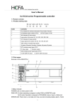
HCFA CORPORATION LIMITED
User's manual
for HCA1, HCA2 Series Programmable Controller
HC A1-36X 24Y R( T )- A(D)
① ② ③ ④ ⑤
⑥
Code
Contents
①
HC indicates the Chinese Character Pinyin Initials 'HeChuan
②
A2 indicates series number of PLC. HC PLC Types: A1~A8
③
36X indicates 36 input points; Input points of A1 series: 8X, 12X, 16X
Input points of A2 series: 8X, 14X, 24X, 36X
24Y indicates 24 output points; Output points of A1 series: 6Y、8Y、14Y
Output points of A2 series: 6Y、10Y、16Y、24Y
Total number of input& output points:
A1: 14 points, 20 points, 30 points A2: 14 points, 24 points, 40 points, 60 points
R(T) indicates output type of PLC R: relay output T: transistor output
④
⑤
H(mm)
90
90
90
90
90
90
90
81
81
83
81
81
83
83
●1.4 Performance Specification
Items
A(D) indicates power supply type of PLC
A: AC 85V~264V input D: DC 20.4V~26.4V input
⑥
W(mm)
100.2
130.2
150.2
100.2
130.2
182.2
220.2
HCA1-14X10Y(20 points)
HCA1-20X14Y(30 points)
HCA2-8X6Y(14 points)
HCA2-14X10Y(24 points)
HCA2-24X16Y(40 points)
HCA2-36X24Y(60 points)
► 1. Product overview
●1.1 Product naming rules
L(mm)
Points
HCA1-8X6Y(14 points)
Performance
Built-in 8K EEPROM
8K steps(max.), including comments, file register
Rewrite: 20,000 times
Memory capacity
●
●
●
Install expansion unit/ IO
Optional
Transistor output modules
Optional
High-speed counter
●Increment: 100 kHz* 2 counter, 10 kHz*4 counter
●Up/ down: 100 kHz*1 counter, 10 kHz*1 counter
●Pulse plus direction: 100 kHz * 2 counter
●Differential phases (4×): 50 kHz*1 counter, 5 kHz*1
counter
●1.2 Part names
Pulse output
Example: HCA2-36X24YR-A
Support( Only with transistor output modules)
Rs422 communication port Provided
RS422&485 communication port Provided
HCA2-36X24YR
Corresponding links
●Simple PC links (8 base units(max.) can be connected)
●PC links(can be used as a sub-station connection)
●Parallel links(2 base unit can be linked)
Clock
Provided
Battery
Can be used(Sold separately)
Backup time of capacitor
10 days (at most), at 25 ℃(More than 30 minutes after start-up)
If there are no batteries, we have to do no battery operation.
If power outage more than 8~10 days, only EEPROM data can be kept.
Battery-free operation
► 2 .Power specification
●2.1AC power module Specification
Items
HCA1
20 points
30 points
14 points
AC 100 - 240V, +10% -15%
14 points
24 points
HCA2
40 points
60 points
Rated voltage
Allowable voltage AC 85 - 264V
range
Rated frequency 50/60 Hz
Allowable momentary 10ms, If less than 10 ms, the PLC will continue operation.
power failure period
If 10 ms or more, the PLC will be shut down
①Status indicator POWER LED: Lit when power is ON.
RUN LED: Lit when executing a program
ERROR LED: When program error, indicating lampflashes
When CPU error, indicating lamp lit
②Input indicator: HCA1 HCA2 is octal.
③Output indicator: HCA1 HCA2 is octal.
④RS422&485 communication port: Operating according to arrow directions
⑤RS422 communication port: Operating according to arrow directions
⑥RUN/STOP switch
⑦Terminal cover
⑧The right expansion cover
⑨The front cover, built-in battery interface
⑩Two analog potentiometer opening
Power fuse
In-rush current
250V ,1A
100V AC - Max. 15A for 5ms
200V AC - Max. 25A for 5ms
250V ,3.15A
100V AC - Max. 30A for 5ms
200V AC - Max. 50A for 5ms
Power consumption
19W
20W
21W
29W
30W
32W
24V DC External DC24V 400mA (Have nothing with expansion module connection)
power
35W
1
Attention: Includes Input current (7mA or 5mA perpoint)
●2.2 DC power module Specification
HCA1
Items
14 points
20 points
HCA2
30 points
14 points
24 points
40 points
60 points
Power consumption DC 12~24 V +10% -15%
Allowable voltage range DC 10.2V~28.8V
Allowable momentary 5mS, If less than 5 ms, the PLC will continue operation.
power failure period
If 5 ms or more, the PLC will be shut down
Inrush current
DC 24V - Max. 25A for 1ms
DC 12V - Max. 22A for 0.3ms
14.5W
15W
18W
DC 24V - Max. 10A for 100μs
Power consumption
6.5W
7W
8W
20W
Attention: Includes Input current (7mA or 5mA per point)
►3 .Input / Output wiring diagram
●3.1 Input wiring diagram
Programmable controller(Sinking)
Programmable controller(Sourcing)
Fuse
Fuse
L
L
*
*
N
N
AC100 - 240V
AC100 - 240V
S/ S
S/ S
0V
0V
24V
24V
b)X2-X7 internal structure
c) Internal structure of general input (X10-X43)
●Caution:Unidirectional coupling is used in photocoupler input forall HCA1/HCA2 series, and
all inputs can only be sinking input.
●3.2 Output wiring diagram
3 - wire
sensors
X000
X001
3 - wire
sensors
X000
X001
X002
X002
X003
X003
IN
Input indicators
4.3k
1000pF
IN
Output type
External
power supply
The source / sink connection of input terminal as the example.
3.3k
3.2.1 Relay output specification and wiring
internal
circuit
COM
a)2*100KHz internal circuit of high-speed input
Relay
≤DC30V
≤240V(It should be lower than AC 250V
if not consistent with CE/UL/CUL)
The total load current should not
exceed following values of common
Resistive 2A/1 collector.
Maximum load
point Output 1 point common collector:2A
load
Output 4 point common collector: 8A
Output 8 point common collector: 8A
Inductive
load
Minimum load
Open circuit leakage
current
Response OFF→ON
Time
ON→OFF
Circuit isolation
Operation indication
80VA
Load
Y
Fuse
AC100V
COM
PLC
Short-circuit protection
DC5V 2mA (Reference value)
_
About 10 ms
About 10 ms
Mechanical isolation
When relay coil is energized, LED is lit.
★Precaution:
Protection circuit for load short-circuit: A short-circuit at a load connected to an output terminal
could cause burnout at the output element or the PCB. To prevent this, a protection fuse should
be inserted at the output.
Contact protection circuit of inductive load: An internal protection circuit for the relays is not
provided in the relay output circuit for this product. It is recommended to use inductive loads
with built-in protection circuits. When using loads without built-in protection circuits, insertan
external contact protection circuit composed of surge absorber to reduce electromagnetic
interference and extend the product life
2
●3.2.2 Transistor output specification and wiring
External Power supply
Maximum Resistive load
load
Inductive load
1 . Sinking output wiring
DC5~30V
The total load current should not
exceed the following values of
common collector resistance load.
Output 1 point common collector: 0.5A
Output 4 point common collector: 0.8A
Output 8point common collector: 1.6A
12W/DC 24V
Minimum load
-
Open circuit leakage current
≤0.1 mA / DC30V
ON Voltage
≤1.5V
Load
Y
Fuse
COM
PLC
2. Sourcing output wiring
Load
Y
●Please note that if we use contact device of analog switch to count, switch vibration may
cause counting error.
●I f h i g h - s p e e d c o u n t e r c o i l p r o g r a m m e d , t h e c o r r e s p o n d i n g i n p u t f i l t e r i n i n p u t r e l a y w i l l
automatically be 20μs (X000, X001) or 50μs (X002~X005) (initial value: 10 ms)
●Serial number of input relay cannot be used with same input instructions at the same time,
e.g: Input interrupt processing(pointer), pulse output density instruction SPD
●Output contact points of high-speed counters will not execute instructions even with current
value, unless counting input pulse set.
●When output coil of high-speed counte(
r OUT C***)
on/off, it can start/ stop execution counting.
Output coil should be programmed in the main program. If programmed in step ladder circuit,
subroutine, interrupt handlers, Counting and Counting Stop Function can work until step ladder
circuit and subroutine perform.
Fuse
●4.2 High-speed counter output example (only applicable to transistor output)
+V
Pulse volume
PLC
Frequency(K1000)
Export
● Attention:All outputs are set as sinking output modes in all HCA1/ HCA2 series with transistor
output.
► 4 .High-speed counter input/ pulse output instruction
[Input] high-speed counter function
1 phase: 60kHz * 2 points,10kHz *4 points 2 phase: 30kHz * 1 points, 5kHz X1 points
[Input] Pulse latch function
To capture signal of 10μs(X0,X1) or 50μs(X2~X5)
[Input] external interrupt function
By external signals of 10μs(X000,X001) or 50μs(X002~X005),it can process interrupt program
first.
[Output] pulse output function
2 pulse train outputs 100kHz (max.) at the same time(transistor output base units only). With
special positioning instruction of ZRN, DRVI、DRVA.
●4.1 High-speed counter input example
High-speed counter coil drive depends on Contact points. In high-speed counting, please use energized contact
points.
Example: M8000(monitoring)
●PLSY instruction: produces quantitative pulse with assigned frequency
S1: assigned frequency
HC1A,HC2A:16-bit instruction→1~32,767(HZ), 32-bit instruction→1~100,000(HZ)
When S1specified word device changes during instruction execution, output frequency changes
accordingly.
S2: assigned pulse volume
●Allowable setting range: 16-bit instruction→1~32,767(PLS), 32-bit instruction→1~2,147,
483,647(PLS)
Setting value is zero, the generated pulse do no limit.
In DPLSY instruction, (D1,D0)can be set as pulse value.
During instruction execution , when S2 specified word device changes, it starts executing change
instruction in next instruction drive.
D specifies Y serial number of output pulse, only valid with Y000 or Y001(Please use transistor
output mode)
●X000 is OFF, output interrupts. Reset NO, it starts from initial state. Continuous pulse occurs,
X000 will be OFF,Y000 will be OFF ,too.
●Duty ratio of pulse is 50%ON, 50%OFF. Output control is not affected by scan cycle, then
interrupt processing.
●Pulse completing, marking the end of M8029 action
●5.Terminal arrangements for HCA1 &HCA2 series
HCA1-6X4Y口-A
HCA1-8X6Y口-A
Input number corresponding to C235
Please use contact points in countingWhen specifying counting number into relay,
Intermittent while programmingHigh-speed counter cannot count correctly
3
HCA1-12X8Y口-A
HCA2-8X6Y口-A
HCA1-16X14Y口-A
HCA2-14X10Y口-A
HCA2-24X16Y口-A
HCA2-36X24Y口-A
Manual number:DOC- HCA1 HCA2
Micro programmable controller instruction manual
Manual version: V1.0
Date: Jan.5th , 2013
HCFA Corporation Limited
4


