1
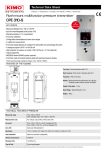
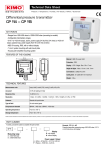
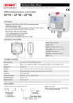
Multifunction transmitter
C 310
KEY POINTS
- 2 inputs for interchangeable probes
- 1 location for interchangeable SPI-2 board
- Simultaneous display of 1 to 4 parameters
- Trend indicator
- 4 visual (dual-color LEDs) and audible alarms
- 2 analogue outputs (4 wires) 0/5-10 V or 0/4-20 mA, 2 additional outputs (optional)
- 4-relay board (optional)
- 24 Vdc/Vac or 115/230 Vac power supply
- Outputs diagnostic
- Ethernet communication (optional)
- MODBUS network RS485 system (optional)
- ABS housing with stainless steel front, IP65, with or without backlit graphic display
- “¼ turn” system mounting with wall-mount plate
FEATURES OF THE HOUSING
158 mm
Material : ABS V0 as per UL94
81 mm
Protection : IP65
111 mm
Display : Graphic from 1 to 4 lines, 240 x 128 px ;
Size : 86 x 51 mm,
Backlit
Height of digits : Values : 10 mm ; Units : 5 mm
Cable gland : in polyamide for cables Ø 9 mm maximum
25 mm
Weight : 700 g
PART NUMBERS
●
●
C310-BO : multifunction transmitter, 24 Vac/Vdc power supply, with display
C310-BN : multifunction transmitter, 24 Vac/Vdc power supply, without display
●
●
C310-HO : multifunction transmitter, 115-230 Vac power supply, with display
C310-HN : multifunction transmitter, 115-230 Vac power supply, without display
TECHNICAL SPECIFICATIONS
Power supply
24 Vac / Vdc ±10 %
115 Vac to 230 Vac ±10 %, 50-60 Hz
Outputs
2 x 0/4-20 mA or 2 x 0-5/10 V (4 wires) or
4 x 0/4-20 mA or 4 x 0-5/10 V (optional)
Maximum load : 500 Ohms (0/4-20 mA) / Minimum load : 1 K Ohms (0-5/10 V)
Galvanic isolation
Inputs (power supply) and outputs (on 115 Vac/230 Vac models)
Outputs (on 24 Vac/Vdc models)
Consumption
10 W
Relays
4 RCR relays 5 A / 230 V (optional)
Conformity
CEM 2004/108/CE and NF EN 61010-1 directives
Electrical connections
Screw terminal block for cables from 0.05 to 2.5 mm2 or from 30 to 14 AWG
RS485 communication
Digital : Modbus RTU protocol, configurable communication speed from 2400 to 115200 Bauds (optional)
Ethernet communication
Ethernet communication module allowing transmission, monitoring and maintenance of transmitters via an Ethernet
network in 10 BASE-T and 100 BASE-TX LAN/WAN supporting TCP/IP protocol (optional)
TECHNICAL SPECIFICATIONS
Environment and type of fluid
Air and neutral gases
Operating/Storage temperature
From -10 to +50 °C / From -10 to +70 °C
RELAYS AND ALARMS
The C 310 transmitter has 4 independent and configurable alarms : these are visual and audible alarms and it is possible to couple them with 4
relays (optional).
Available settings :
●
Selection of the parameter (pressure, air velocity, temperature,...)
● Time-delays duration from 0 to 600 s
● Alarm action : rising edge, falling edge, monitoring or state of the transmitter
● Operating mode of the relays : negative or positive safety (optional)
● Activation of the audible alarm (buzzer) that can be acknowledged by the front keypad (optional)
CONNECTIONS
RS 485 connection(d)
Analogue outputs (a)
(optional)
(OUT3 and OUT4 are optional)
Autozero
SPI-2 board
(optional)
Solenoid valve
Relays board (b)
(optional)
LCC-S
software
connection
Power supply
terminal block (c)
Type of power
supply of the
transmitter
Ethernet board
(optional)
Probes
connection
(b)
Relay 2
Relay 3
Relay 4
NO : Normally open
COM : Common
NC : Normally closed
NO : Normally open
COM : Common
NC : Normally closed
0/4-20 mA – Current
GND – Ground
0-5/10 V - Voltage
GND – Ground
0-5/10 V - Voltage
Analogue output 3 Analogue output 4
(OUT3)
(OUT4)
0/4-20 mA – Current
0/4-20 mA – Current
GND – Ground
0-5/10 V - Voltage
GND – Ground
0-5/10 V - Voltage
0/4-20 mA – Current
Relay 1
NO : Normally open
COM : Common
NC : Normally closed
(a)
Optional
Analogue output 1 Analogue output 2
(OUT1)
(OUT2)
Cable glands
NO : Normally open
COM : Common
NC : Normally closed
Pressure
connection
(optional)
(c)
(c)
For 24 Vdc/Vac power supply models :
or
(d)
For 115 Vac or 230 Vac power supply models :
Modbus :
Phase (L)~
Neutral (N)~
Ground
Phase (L) +
Neutral (N) -
Ground
1 2 3
GND A B
+ -
ELECTRICAL CONNECTIONS – as per NFC15-100 Norm
This connection must be made by a qualified technician. Whilst making the connection, the transmitter must not be energized.
For 24 Vdc power supply models :
➢
-
+
-
+
➢
For 115 Vac or 230 Vac power supply models:
L
N
L
115/230 Vac
power supply
24 Vdc
power supply
➢
N
For 24 Vac power supply models :
N
N
L
L
or
230 Vac
Pe
N
L
N
L
24 Vac
24 Vac power supply
class II
➢
0/4-20 mA current output connection :
0/4-20 mA
0-5/10 V
GND
+
-
Regulator display or
PLC/BMS
passive type
230 Vac
Pe
N
N
L
L
24 Vac
24 Vac power supply
➢
0-5/10 V voltage output connection :
0/4-20 mA
0-5/10 V
GND
-
+
Regulator display or
PLC/BMS
passive type
RS 485 MODBUS PROTOCOL (optional)
Class 310 transmitters can be linked in one network operating on a RS485 home bus.
The RS 485 digital communication is a 2-wire network, on which the transmitters are connected in parallel. They are connected to a PLC/BMS via the RTU
Modbus communication system. Since the C310 can be configured with the keypad, the MODBUS enables remote configuration, to measure 1 or 2 parameters
or to see the status of the alarms...
ETHERNET BOARD (optional)
An Ethernet board can put put on a C310 transmitter allowing for each transmitter to have a specific configurable IP address. So the user can remotely
interrogate the transmitter, retrieve data, modify the configuration,...
It is also possible to integrate C310 transmitters into a computer network via the RJ45 connection located at the bottom of the transmitter.
CONFIGURATION
Class 310 transmitters allows you to set all the parameters managed by the transmitter : units, measuring ranges, alarms, outputs, channels... via the different
methods shown below :
➢ Via keypad, only on models with display. A code-locking system for keypad guarantees the security of the installation. See configuration manual.
➢ Via software (optional) : simple and user-friendly. See LCC-S user manual.
➢ Via Modbus (optional) : configuration of all parameters from your PC, via the supervision or data acquisition software.
➢ Via Ethernet (optional) : configuration of all parameters from your PC, via the supervision or data acquisition software.
MOUNTING
To install the transmitter on a wall, fix the stainless steel plate to the wall (drilling : Ø8 mm, screws and wall-plugs supplied).
Insert the transmitter on the plate (see A on the drawing below) by aligning it at 30°. Rotate the housing in clockwise direction until you heard a “click” which
confirms that the transmitter is correctly installed. Open the housing, lock the clamping system of the housing on the plate with the screw (see photo below).
To remove the transmitter from the fixing plate, do not forget to remove this screw.
A
65 mm
Ø 5,4 mm
316 L stainless steel plate
Fixing screw of the housing
CALIBRATION
Adjusting and calibration on site : the professional configuration interface, with a dynamic pressure calibration bench, allows you to adjust and calibrate your
transmitters directly on site or in laboratories.
Outputs diagnostics : with this function, you can check with a multimeter (or on a regulator/display, or on a PLC/BMS) if the transmitter outputs work properly.
The transmitter generates a voltage of 0 V, 5 V and 10 V or a current of 0 mA, 4 mA, 12 mA and 20 mA
Certificate : transmitters are supplied with an individual adjusting certificate and can be supplied with a calibration certificate as an option.
MAINTENANCE
Avoid aggressive solvents. When cleaning rooms or ducts with products containing formol, protect the the transmitter.
OPTIONS
●
●
●
●
●
●
●
●
LCC-S : configuration software with USB cable.
SQR/3 function : (square root extraction) function for the calculation of air velocity and airflow.
RS5 : RS 485 Protocol Modbus digital output
O2S : 2 additional analogue output
C4R : 4 relays board
CETHE : Ethernet network board
HRP : high resolution (example in pressure : 0.1 Pa) with SPI2-100 board
Calibration certificate
FTang – transmitter_C310 – 20/12/13 – RCS (24) Périgueux 349 282 095 Non-contractual document – We reserve the right to modify the characteristics of our products without prior notice.
A
65 mm
98 mm
120 mm