1
Installation and Assembly:
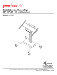
Straight Column Mount for 32" - 71" Flat Panel Displays
Model
Max. Load
PLCM-1CP
225 lb. (102.3 kg.)
PLCM-UNL-CP 200 lb. (90.7 kg.)
Screen Size Range
32'' - 71''
32'' - 65''
NOTE: Read entire instruction sheet before you start installation and assembly.
WARNING
• Do not begin to install your Peerless product until you have read and understood the instructions and warnings
contained in this Installation Sheet. If you have any questions regarding any of the instructions or warnings, for US
customers please call Peerless customer care at 1-800-865-2112, for all international customers, please contact
your local distributor.
• This product should only be installed by someone of good mechanical aptitude, has experience with basic building
construction, and fully understands these instructions.
• Make sure that the supporting surface will safely support the combined load of the equipment and all attached
hardware and components.
• Never exceed the Maximum UL Load Capacity.
• If mounting to wood wall studs, make sure that mounting screws are anchored into the center of the studs. Use of
an "edge to edge" stud finder is highly recommended.
• Always use an assistant or mechanical lifting equipment to safely lift and position equipment.
• Tighten screws firmly, but do not overtighten. Overtightening can damage the items, greatly reducing their holding
power.
• This product is intended for indoor use only. Use of this product outdoors could lead to product failure and personal
injury.
2300 White Oak Circle • Aurora, Il 60502 • (800) 865-2112 • Fax: (800) 359-6500 • www.peerless-av.com
ISSUED: 08-20-02 SHEET #: 200-9405-13 (2014-03-17)
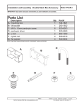
Before you begin, make sure all parts shown are included with your product.
Parts List
Description
ceiling arm box
tilt bracket
33" support pipe
retaining collar
M5 x 10 mm penta-pin™ screw
.062" fiber washer
M10 x 15 mm penta-pin screw
M10 penta-pin tool
M5 penta-pin tool
M5 x 8 mm phillips Type F screw
ceiling plate
ceiling plate end cap
wood screw
A
B
C
D
E
F
G
H
I
J
K
L
M
Qty
1
1
1
1
4
1
8
1
1
4
1
2
4
PLCM-1CP
Part #
201-1062
200-1552
139-1088
1800-375
505-9010
540-9432
520-9263
520-9260
520-9249
520-1167
128-1039
2PT-22CA01D
5S1-015-C03
PLCM-UNL-CP
Part #
201-1062
200-1552
139-1088
1800-375
505-9010
540-9432
520-9263
520-9260
520-9249
520-1167
128-1039
2PT-22CA01D
5S1-015-C03
Parts may appear slightly different than illustrated.
A
D
Parts List
AA
BB
CC
DD
EE
FF
Description
adapter plate
shallow vertical brackets
M5 x 10 mm socket pin screw
M10 x 15 mm socket screws
6 mm allen wrench
4mm allen wrench
Qty
1
2
4
4
1
1
PLCM-1CP
Part #
-
E
F
PLCM-UNL-CP
Part #
201-1110
201-1511
520-1063
520-9262
560-9716
560-9646
G
J
H
B
I
K
L
M
C
2 of 10
ISSUED: 08-20-02 SHEET #: 200-9405-13 (2014-03-17)
L ceiling plate end cap
M wood screw
2
4
Parts List
AA
BB
CC
DD
EE
FF
Description
adapter plate
shallow vertical brackets
M5 x 10 mm socket pin screw
M10 x 15 mm socket screws
6 mm allen wrench
4mm allen wrench
Qty
1
2
4
4
1
1
2PT-22CA01D
5S1-015-C03
2PT-22CA01D
5S1-015-C03
PLCM-1CP
Part #
-
PLCM-UNL-CP
Part #
201-1110
202-1655
520-1063
520-9262
560-9716
560-9646
BB
AA
CC
DD
EE
FF
Security Adapter Bracket Fasteners
M4 x 12 mm (6)
510-1079
M5 x 12 mm (4)
520-1064
M4 x 25 mm (4)
510-1082
M6 x 30 mm (4)
520-1067
M6 x 12 mm (4)
520-1050
M6 x 25 mm (4)
520-1211
M8 x 15 mm (6)
520-1068
M6 x 20 mm (4)
520-9554
M5 x 25 mm (4)
520-1122
M8 x 25 mm (4)
520-1101
multi-washer (6)
580-1036
I.D. .22" (5.6 mm) (4)
540-1057
I.D. .34" (8.7 mm ) (4)
540-1059
3 of 10
M8 x 40 mm (4)
520-1152
ISSUED: 08-20-02 SHEET #: 200-9405-13 (2014-03-17)
Installing Adapter Brackets
WARNING
• Tighten screws so adapter brackets are firmly attached. Do not tighten with excessive force. Overtightening can
cause stress damage to screws, greatly reducing their holding power and possibly causing screw heads to become
detached. Tighten to 40 in. • lb (4.5 N.M.) maximum torque.
• If screws don't get three complete turns in the display inserts or if screws bottom out and bracket is still not tightly
secured, damage may occur to display or product may fail.
1
To prevent scratching the display, set a cloth on a flat, level surface that will support the weight of the display.
Place display face side down. If display has knobs on the back, remove them to allow the adapter brackets to be
attached. Place adapter brackets (BB) on back of display, align to holes, and center on back of display as shown
below. Attach the adapter brackets to the back of the display using the appropriate combination of screws, multiwashers and spacers as shown in step 1-1 and step 1-2.
NOTE: Top and bottom holes on display must always be used.
Verify that all holes are properly aligned, and then tighten screws using a phillips screwdriver.
NOTE: Tighten using security allen wrench (FF).
X
BB
CENTER BRACKETS
VERTICALLY ON BACK OF
DISPLAY
X
Note: "X" dimensions should be equal.
Notes:
MULTI-WASHER
MEDIUM HOLE FOR M5 SCREWS
• The number of fasteners used will vary,
depending upon the type of display.
• Multi-washers and spacers may not be
used, depending upon the type of display.
SMALL HOLE FOR M4 SCREWS
LARGE HOLE FOR M6 SCREWS
• Use the corresponding hole in the multi-
washer that matches your screw size as
shown.
NOTE: For flat back displays proceed to step 1-1. For bump-out or recessed back display skip to step 1-2.
4 of 10
ISSUED: 08-20-02 SHEET #: 200-9405-13 (2014-03-17)
For Flat Back Display
1-1
Begin with the shortest length screw, hand thread through multi-washer and adapter bracket into display as
shown below. Screw must make at least three full turns into the mounting hole and fit snug into place. Do not
over tighten. If screw cannot make three full turns into the display, select a longer length screw from the baffled
fastener pack. Repeat for remaining mounting holes, level brackets and tighten screws.
NOTE: Spacers may not be used, depending upon the type of display.
DISPLAY
MULTI-WASHER
SCREW
ADAPTER
BRACKET
(BB)
If you have any questions, please call Peerless customer care at 1-800-865-2112.
For Bump-out or Recessed Back Display
1-2
Begin with longer length screw, hand thread through multi-washer, adapter bracket and spacer in that order into
display as shown below. Screw must make at least three full turns into the mounting hole and fit snug into place.
Do not over tighten. If screw cannot make three full turns into the display, select a longer length screw from the
baffled fastener pack. Repeat for remaining mounting holes, level brackets and tighten screws.
DISPLAY
MULTI-WASHER
SPACER
SCREW
ADAPTER
BRACKET
(BB)
If you have any questions, please call Peerless customer care at 1-800-865-2112.
5 of 10
ISSUED: 08-20-02 SHEET #: 200-9405-13 (2014-03-17)
2
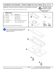
For Wood Joist Finished Ceiling, Exposed Wood
Joists, or Wood Beam Ceiling. Drill four 5/32"
(4 mm) dia. holes to a minimum depth of 2.5"(64
mm) INTO JOIST CENTERS. Attach ceiling plate
(K) with four wood screws (M) using a 3/8"(10 mm)
socket wrench. Tighten wood screws (M) so ceiling
plate is firmly attached. Snap end caps (L) into
place.
L
K
WARNING
• Tighten wood screws so that ceiling plate is firmly
attached, but do not overtighten. Overtightening
can damage screws, greatly reducing their holding
power.
M
• Never tighten in excess of 80 in • lb (9 N.M.).
• Make sure that mounting screws are anchored into
the center of the joists. The use of an "edge to edge"
stud finder is highly recommended.
2
For Concrete Ceilings drill four 5/16"(8 mm) dia.
holes to a minimum depth of 1 3/4" (45 mm). Attach
ceiling plate (K) using concrete expansion anchors
as shown in 2-1 and 2-2. Then snap end caps (L)
into place.
Align hole in ceiling plate with hole in ceiling.
Gently hammer in concrete anchor.
Use a 10 mm wrench to tighten concrete anchor
to 80 in • lb (9 N.M.) maximum torque to expand
anchors.
ACC210
FOR PRODUCT SAFETY USE ONLY RAWL™
#5005 OR HILTI™ HL814 CONCRETE ANCHORS.
Order accessory kit #ACC210 which contains four
.312 x 1.625 concrete expansion anchors.
2-1
2-2
WARNING
• Always attach concrete expansion anchors directly
to load-bearing concrete.
• Never attach concrete expansion anchors to
concrete covered with plaster, drywall, or other
finishing material.
PLASTER/
DRYWALL
CONCRETE
6 of 10
ISSUED: 08-20-02 SHEET #: 200-9405-13 (2014-03-17)
Installing Adapter Bracket
3
Using the hole pattern shown below, attach adapter plate (AA) to tilt bracket (B) with four M10 x 15 mm screws (G).
Tighten screws using M10 penta-pin tool (H).
G
AA
B
7 of 10
ISSUED: 08-20-02 SHEET #: 200-9405-13 (2014-03-17)
4
Thread support pipe (C) into threaded fitting in ceiling plate (K). Align with one small hole in the side of the ceiling
plate threaded fitting. Insert and tighten one M5 x 10 mm penta-pin screw (E) as shown. Tighten screw using M5
penta-pin tool (I). Insert four M10 x 15 mm penta-pin screws (G) into threaded holes in the sides of ceiling arm box
(A). Leave approximately 1/4" of exposed thread. Slide ceiling arm box (A) and fiber washer (F) onto end of support
pipe. Thread retaining collar (D) onto support pipe. Allow ceiling arm box (A) to rest on top of retaining collar (D).
Insert and tighten one M5 x 10 mm penta-pin screw (E) into retaining collar (D) as shown. Insert one M5 x 10 mm
penta-pin screw (E) through the tab on the back of ceiling arm box (A). Use M5 penta-pin tool (I) to tighten screws.
Do not over tighten.
Note: UL Listed AEC or EXT extension column series can be used in combination with, or in place of support pipe
(C) to achieve different lengths.
K
E
C
E
BACK OF
CEILING
ARM BOX
A
G
G
F
1/4"
D
D
E
8 of 10
ISSUED: 08-20-02 SHEET #: 200-9405-13 (2014-03-17)
5
Hang tilt bracket (B) onto ceiling arm box (A). Adjust tilt as desired and tighten four M10 x 15 mm penta-pin screws
(G) using M10 penta-pin tool (H).
WARNING
• For a safe assembly be sure to fully tighten four
screws (G).
B
A
G
9 of 10
ISSUED: 08-20-02 SHEET #: 200-9405-13 (2014-03-17)
Mounting and Removing Flat Panel Display
WARNING
• Always use an assistant or mechanical lifting equipment to safely lift and position the plasma television.
6
Hook adapter brackets (BB) onto universal PLP plate (AA), then slowly swing display in as shown. Turn safety/
security screws clockwise at least six times to prevent display from being removed as shown in detail 1.
Tighten all fasteners using wrench (FF).
Display can be adjusted horizontally if desired as shown in figure 6.1.
NOTE: To lock the display down, tighten safety/security screws to adapter bracket as shown in detail 1.
To remove display from mount, loosen safety/security screws, swing display away from mount, and lift display off of
mount.
BB
Fig. 6.1
AA
SAFETY/SECURITY
SCREWS AA
BB
DETAIL 1
Utility Patent No. 8,517,322
10 of 10
ISSUED: 08-20-02 SHEET #: 200-9405-13 (2014-03-17)
© 2014, Peerless Industries, Inc. All rights reserved.
All other brand and product names are trademarks or registered trademarks of their respective owners.